US1856834A - Tile and pipe form - Google Patents
Tile and pipe form Download PDFInfo
- Publication number
- US1856834A US1856834A US508304A US50830431A US1856834A US 1856834 A US1856834 A US 1856834A US 508304 A US508304 A US 508304A US 50830431 A US50830431 A US 50830431A US 1856834 A US1856834 A US 1856834A
- Authority
- US
- United States
- Prior art keywords
- pipe
- casing
- tile
- members
- spreader
- Prior art date
- Legal status (The legal status is an assumption and is not a legal conclusion. Google has not performed a legal analysis and makes no representation as to the accuracy of the status listed.)
- Expired - Lifetime
Links
- XLYOFNOQVPJJNP-UHFFFAOYSA-N water Substances O XLYOFNOQVPJJNP-UHFFFAOYSA-N 0.000 description 9
- 239000011148 porous material Substances 0.000 description 5
- 230000000295 complement effect Effects 0.000 description 3
- 238000005299 abrasion Methods 0.000 description 2
- 238000010276 construction Methods 0.000 description 2
- 238000003973 irrigation Methods 0.000 description 2
- 230000002262 irrigation Effects 0.000 description 2
- 230000006978 adaptation Effects 0.000 description 1
- 230000015572 biosynthetic process Effects 0.000 description 1
- 239000004568 cement Substances 0.000 description 1
- 238000007599 discharging Methods 0.000 description 1
- 238000007654 immersion Methods 0.000 description 1
- 239000000203 mixture Substances 0.000 description 1
- 238000003825 pressing Methods 0.000 description 1
- 239000002689 soil Substances 0.000 description 1
- 239000007787 solid Substances 0.000 description 1
Images
Classifications
-
- B—PERFORMING OPERATIONS; TRANSPORTING
- B28—WORKING CEMENT, CLAY, OR STONE
- B28B—SHAPING CLAY OR OTHER CERAMIC COMPOSITIONS; SHAPING SLAG; SHAPING MIXTURES CONTAINING CEMENTITIOUS MATERIAL, e.g. PLASTER
- B28B21/00—Methods or machines specially adapted for the production of tubular articles
- B28B21/76—Moulds
- B28B21/82—Moulds built-up from several parts; Multiple moulds; Moulds with adjustable parts
Definitions
- My invention relates to tile and pipe forms and certain objects of the invention are to provide a form comprising means wherein short lengths of pipe may be moulded and removed therefrom while in the semi-solid state without damage or abrasion of the surface pores and whereby the pipes may thus solidify or set with a maximiun degree of porosity, the ultimate objects of the invention being to provide pipes that are wholly porous throughout and some of which may afterwards be made partly watertight and totally watertight for the purpose of conveying water across land for irrigation and discharging some of the water through the porous portions of the pipe line as hereinafter set forth.
- Fig. 2 is a top plan view of the same
- Fig. 3 is a view in central vertical section taken substantially on a broken line 3, 3 of Fig. 2;
- Fig. 4 is a. similar view taken on a broken line 4, 4 of Fig. 3.
- the numerals 5 and 6 designate the two halves of the outside cylindrical shell or casing that ordinarily rest on a wooden base board 7. Said halves are each provided with a plurality of complementary lugs 8 that coincide when the edges of the casing are placed together. Vertical rods 9 and 10 are passed through said lugs to fasten said cylindrical halves together and are provided with upper hooked ends 11. Said rods also pass downwardly through holes 12 in the base board and either or both may be lifted out by their hooked ends and removed when it is desired to open and remove the cylinder as will be understood.
- a large hole 13 is cut through .the base board 7 in concentric alignment with the small hole-s 12 and is adapted to receive the lower ends of a ypair of semi-cylindrical core members 14 and 15 that project upwardly above the outside casing as shown in Figs. 1 and 4 of the drawings.
- An equal portion is cut away from the inner faces of Said two core members to provide a space sufficient to snugly receive a spreader member 16.
- Said spreader extends to the bottom of the 'oase board and entirely above said cor-e members where it is provided with a handle portion 17 whereby it may be lifted out.
- Said upper portion is members 18 that fit into guides 19 formed on the upper exterior ends of the shell members 5 and 6, and fingers 20 that fit into holes 21 in the core members.
- the concrete 23, or other mixture for forming the pipe or tile is poured or filled in from the top and allowed to remain for a short time or until it has just reached the point of set whereby it will stand by itself.
- the vspreader meml ber 16 is then lifted out by its handle 17 and the core members 14 and 15 are then pressed together and lifted out. After thisone or also provided with a pair of wing 5.
- both of the rods 9 and 10 are lifted out and the casing members 5 and 6 are removed. If only one of said rods is removed the casing is opened like a hinge. It will be noted that the core and casing members are removed laterally and bodily away from the concrete pipe. Abrasion or rubbing of the concrete surfaces which closes the pores and prevents the formation of a perfectly porous pipe is thus prevented and the pipe is free to dry out by itself without being in Contact with any object thus ensuring a perfectly porous pipe.
- the pipes may be made watertight in part longitudinally so that the bottom parts may prevent the escape of water while the upper parts may be left porous and permit the passage of water through the pores by applied pressure.
- the porous pipe may be readily made watertight by immersion in a thin cement paste or solution as will be understood.
- a tile and pipe form having in combination an outer casing comprising two cylindricalk halves, a base board restA for said casing, complementary spaced apart lugs for the adjoining edges of said halves, rods for the adjoining edges passing vthrough said lugs and intothe base board, said base board having a large holeJ in concentric alignment with the rod'holes, a pair of complementary substantially semi-cylindrical core members, a spreader membery interposed between said core members the edge surfaces of the spreader having the sameI curvature and laying in the same cylindrical surface as the exterior surfacesof the said substantially semi-'cylindrical core members, said core and spreader members seated in said large hole and proj ecting exteriorly above said casing, wings for the upper portion of said spreader, guides on the upper exterior ends of the cylindrical casing members
Landscapes
- Engineering & Computer Science (AREA)
- Manufacturing & Machinery (AREA)
- Chemical & Material Sciences (AREA)
- Ceramic Engineering (AREA)
- Mechanical Engineering (AREA)
- Road Paving Structures (AREA)
Description
May 3, 1932- c. w. HATFIELD TILE AND PIPE FORM Filed Jan. lv2, 1931 Patented May 3, 1932 UNITED STATESv i CLARK W. HATFIELD, 0F SEAIPILE,YVVASHINGTO1\l'Y TILE AND PIPE FORM Application led January 12, 1931. Serial No. 508,304.
My invention relates to tile and pipe forms and certain objects of the invention are to provide a form comprising means wherein short lengths of pipe may be moulded and removed therefrom while in the semi-solid state without damage or abrasion of the surface pores and whereby the pipes may thus solidify or set with a maximiun degree of porosity, the ultimate objects of the invention being to provide pipes that are wholly porous throughout and some of which may afterwards be made partly watertight and totally watertight for the purpose of conveying water across land for irrigation and discharging some of the water through the porous portions of the pipe line as hereinafter set forth.
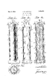
With the above and other objects in view which will appear as the description proceeds, the invention consists of the novel construction, adaptation, combination and arrange ment of parts hereinafter described and claimed. These objects are accomplished by devices illustrated in the accompanying drawings, wherein Figure 1 is a view in side elevation of the pipe form;
Fig. 2 is a top plan view of the same;
Fig. 3 is a view in central vertical section taken substantially on a broken line 3, 3 of Fig. 2; and
Fig. 4 is a. similar view taken on a broken line 4, 4 of Fig. 3.
Referring to the drawings throughout which like reference numerals indicate like parts, the numerals 5 and 6 designate the two halves of the outside cylindrical shell or casing that ordinarily rest on a wooden base board 7. Said halves are each provided with a plurality of complementary lugs 8 that coincide when the edges of the casing are placed together. Vertical rods 9 and 10 are passed through said lugs to fasten said cylindrical halves together and are provided with upper hooked ends 11. Said rods also pass downwardly through holes 12 in the base board and either or both may be lifted out by their hooked ends and removed when it is desired to open and remove the cylinder as will be understood.
A large hole 13 is cut through .the base board 7 in concentric alignment with the small hole-s 12 and is adapted to receive the lower ends of a ypair of semi-cylindrical core members 14 and 15 that project upwardly above the outside casing as shown in Figs. 1 and 4 of the drawings. An equal portion is cut away from the inner faces of Said two core members to provide a space sufficient to snugly receive a spreader member 16. Said spreader extends to the bottom of the 'oase board and entirely above said cor-e members where it is provided with a handle portion 17 whereby it may be lifted out. Said upper portion is members 18 that fit into guides 19 formed on the upper exterior ends of the shell members 5 and 6, and fingers 20 that fit into holes 21 in the core members.
Thus, in the assembled position, it will be seen that all the elements of the device are held rigidly and detachably in place, the rods 9 and 10 holding the casing, the hole 13 holding the bottoms of the core members 14 and 15 and the spreader 16, the lugs 19 holding 75 the upper end of said spreader and the fingers 21 holding the upper ends of the core members concentrically in place. Thusv an annular space 22 is provided between the outside shell or casing and the core members to receive the concrete 23 as shown inF ig. 4.
In the use of my device the concrete 23, or other mixture for forming the pipe or tile, is poured or filled in from the top and allowed to remain for a short time or until it has just reached the point of set whereby it will stand by itself. The vspreader meml ber 16 is then lifted out by its handle 17 and the core members 14 and 15 are then pressed together and lifted out. After thisone or also provided with a pair of wing 5.
both of the rods 9 and 10 are lifted out and the casing members 5 and 6 are removed. If only one of said rods is removed the casing is opened like a hinge. It will be noted that the core and casing members are removed laterally and bodily away from the concrete pipe. Abrasion or rubbing of the concrete surfaces which closes the pores and prevents the formation of a perfectly porous pipe is thus prevented and the pipe is free to dry out by itself without being in Contact with any object thus ensuring a perfectly porous pipe.
The ultimate advantages in the use of a perfectly porous pipe are many. It has been found that pipes made in the herein described manner will carry water long distances when no great pressure is applied. It has also been found that the water may be forced through the pores of the pipe by closing one end and applying pressure to the other end. The advantages in this feature are that water may be conveyed to an elevated storage reservoir during the wet season through the pipes and distributed back over the soil through the same pipes during the dry season by closing the lower end thereof and applying suiicient pressure to force the Water through the pores of the pipe. Further advantages reside in the fact that the pipe may be made watertight in sections and left porous in sections whereby water may be conveyed over ground where no irrigation is needed or desired and forced through to the land where it is wanted at one and the same time. Furthermore the pipes may be made watertight in part longitudinally so that the bottom parts may prevent the escape of water while the upper parts may be left porous and permit the passage of water through the pores by applied pressure. The porous pipe may be readily made watertight by immersion in a thin cement paste or solution as will be understood.
Having thus described my invention, it being understood that minor changes may be resorted to in its construction without departing from` its scope and spirit, what I claim and desire to secure by Letters Patent of the United States is A tile and pipe form having in combination an outer casing comprising two cylindricalk halves, a base board restA for said casing, complementary spaced apart lugs for the adjoining edges of said halves, rods for the adjoining edges passing vthrough said lugs and intothe base board, said base board having a large holeJ in concentric alignment with the rod'holes, a pair of complementary substantially semi-cylindrical core members, a spreader membery interposed between said core members the edge surfaces of the spreader having the sameI curvature and laying in the same cylindrical surface as the exterior surfacesof the said substantially semi-'cylindrical core members, said core and spreader members seated in said large hole and proj ecting exteriorly above said casing, wings for the upper portion of said spreader, guides on the upper exterior ends of the cylindrical casing members adapted to receive said wings, and fingers for the upper portion of the spreader member arranged to seat in holes in the tops of the core members.
In testimony whereof I afiX my signature.
CLARK W. HATFIELD.
Priority Applications (1)
| Application Number | Priority Date | Filing Date | Title |
|---|---|---|---|
| US508304A US1856834A (en) | 1931-01-12 | 1931-01-12 | Tile and pipe form |
Applications Claiming Priority (1)
| Application Number | Priority Date | Filing Date | Title |
|---|---|---|---|
| US508304A US1856834A (en) | 1931-01-12 | 1931-01-12 | Tile and pipe form |
Publications (1)
| Publication Number | Publication Date |
|---|---|
| US1856834A true US1856834A (en) | 1932-05-03 |
Family
ID=24022194
Family Applications (1)
| Application Number | Title | Priority Date | Filing Date |
|---|---|---|---|
| US508304A Expired - Lifetime US1856834A (en) | 1931-01-12 | 1931-01-12 | Tile and pipe form |
Country Status (1)
| Country | Link |
|---|---|
| US (1) | US1856834A (en) |
Cited By (2)
| Publication number | Priority date | Publication date | Assignee | Title |
|---|---|---|---|---|
| US3159898A (en) * | 1962-07-25 | 1964-12-08 | Dougherty J J | Removable form for concrete jacket |
| CN107775779A (en) * | 2016-08-31 | 2018-03-09 | 福建广峰电力通信设备有限公司 | A kind of cement rod outer surface is labeled as type method |
-
1931
- 1931-01-12 US US508304A patent/US1856834A/en not_active Expired - Lifetime
Cited By (2)
| Publication number | Priority date | Publication date | Assignee | Title |
|---|---|---|---|---|
| US3159898A (en) * | 1962-07-25 | 1964-12-08 | Dougherty J J | Removable form for concrete jacket |
| CN107775779A (en) * | 2016-08-31 | 2018-03-09 | 福建广峰电力通信设备有限公司 | A kind of cement rod outer surface is labeled as type method |
Similar Documents
| Publication | Publication Date | Title |
|---|---|---|
| US1947413A (en) | Apparatus for forming a covering or sleeve of plastic material upon a wooden pile | |
| US2826484A (en) | Plastic infusor float | |
| US1856834A (en) | Tile and pipe form | |
| US1240376A (en) | Christmas-tree stand. | |
| US2550977A (en) | Concrete block molding form | |
| US1895702A (en) | Bird bath | |
| US2717469A (en) | Float for minnow bucket | |
| US1458145A (en) | Molding apparatus | |
| US1579634A (en) | Apparatus for molding septic tanks | |
| US2930222A (en) | Prefabricated interlocking structural slabs | |
| US2625289A (en) | Water trough | |
| US1457991A (en) | Mold for tiles or blocks of concrete | |
| US2292505A (en) | Tree holder | |
| US1411404A (en) | Apparatus for concreting piles | |
| US821806A (en) | Pneumatic surf-board. | |
| US2302191A (en) | Fishing rod | |
| US4580961A (en) | Cheese mould | |
| US2122181A (en) | System for concrete constructions | |
| US2109078A (en) | Means for casting clay pipe | |
| US1570841A (en) | Flower box | |
| US1339535A (en) | Apparatus for covering submerged piles with concrete | |
| US2662262A (en) | Expansible mold for casting concrete fence posts | |
| US1430763A (en) | Mold | |
| US1448078A (en) | Wall construction | |
| US1456286A (en) | Fencepost mold |