US1856732A - Steam boiler - Google Patents
Steam boiler Download PDFInfo
- Publication number
- US1856732A US1856732A US380780A US38078029A US1856732A US 1856732 A US1856732 A US 1856732A US 380780 A US380780 A US 380780A US 38078029 A US38078029 A US 38078029A US 1856732 A US1856732 A US 1856732A
- Authority
- US
- United States
- Prior art keywords
- boiler
- combustion chambers
- water
- combustion
- sheet
- Prior art date
- Legal status (The legal status is an assumption and is not a legal conclusion. Google has not performed a legal analysis and makes no representation as to the accuracy of the status listed.)
- Expired - Lifetime
Links
- 238000002485 combustion reaction Methods 0.000 description 40
- XLYOFNOQVPJJNP-UHFFFAOYSA-N water Substances O XLYOFNOQVPJJNP-UHFFFAOYSA-N 0.000 description 20
- 238000004326 stimulated echo acquisition mode for imaging Methods 0.000 description 3
- 238000010025 steaming Methods 0.000 description 2
- 241000282326 Felis catus Species 0.000 description 1
- 238000010276 construction Methods 0.000 description 1
- 239000000446 fuel Substances 0.000 description 1
- 230000003137 locomotive effect Effects 0.000 description 1
- 239000013049 sediment Substances 0.000 description 1
Images

Classifications
-
- F—MECHANICAL ENGINEERING; LIGHTING; HEATING; WEAPONS; BLASTING
- F22—STEAM GENERATION
- F22B—METHODS OF STEAM GENERATION; STEAM BOILERS
- F22B7/00—Steam boilers of furnace-tube type, i.e. the combustion of fuel being performed inside one or more furnace tubes built-in in the boiler body
- F22B7/12—Steam boilers of furnace-tube type, i.e. the combustion of fuel being performed inside one or more furnace tubes built-in in the boiler body with auxiliary fire tubes; Arrangement of header boxes providing for return diversion of flue gas flow
Definitions
- This invention relates to improvements in steam boilers and more particularly to marine boilers and it consists of the matters hereinafter described and more particularly pointed out in the appended claim.
- the boilers with which my invention is concerned are those used upon steam vessels and commonly referred to as Scotch marine boilers.
- Such boilers whether of the single or double ended type include, a shell and end plates, furnaces and combustion chambers and re tubes extending between the combustion chambers and end plates.
- the number of furnaces in each boiler of this kind depends upon the size of the boiler and such a number variesfrom one furnace in the smallest boiler to four in the largest.
- the primary object of the invention is to provide a simple and efficient thermically actuated means whereby boiler water'is withdrawn from the bottom of the boiler and is discharged at a point above the top ends of the combustion chambers whereby circulation and steaming qualities are increased with the assurance that the top of each chamber will be Hooded even though the water level falls below normal.
- Another object of the invention is to provide means which is formed at least in part by the combustion chambers themselves' which acts to cause an upward flow of water between said chambers, thus keeping the same clean through a single ended marine boiler embodying my invention as taken on the line l-l of Fig. 2.
- Fig. 2 is a view partly in front end elevation and in Fig. 1.
- Fig. 3 is a detail horizontal sectional View on an enlarged scale as taken on the line 3-3 of Fig. l.
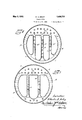
- Fig. 4C is a transverse vertical section n' through a four furnace boiler of this lr1nd,1n
- Fig. 5 is a transverse vertical section through a three vfurnace boiler of this kind, in the plane of the combustion chambers thereof.
- Figs. l to 3 inclusive of the drawings wherein a single ended, two furnace boiler: is shown, Vl indi- Cates the front end plate, 2 indicates the rear end plate and 3 indicates the shell of the boiler.
- the shell is a cylindrical one which engages at its ends upon and is secured in any suitable manner to the inturned anges 4-4 on said end plates.
- a short distance inwardly from the rear end plate 2 is located a pair of upright, combustion chambers 5 5 spaced a short distance apart and one upon each side of the perpendicular median plane of the boiler as a whole.
- Each combustion chamber comprises front and' rear sheets 6 and 7 respectively, an upright inner' sheet 8, a flat top sheet 9, an outer side sheet 10 disposed substantially concentric with respect to the shell 3 and a curved sheet 11 connecting said inner and outer sheet together at the bottom as best shown in Fig. 2.
- each combustion chamber is associated a furnace or fuel burning chamber l2 which opens at one end into the bottom end of said combustion chamber through the front sheet thereof and opens at its other end through .the front end plate l ofthe boiler where it is secured to the integraly annular flange thereof.
- I close the ends of the narrow spaces between adjacent combustion chambers, thus in 4effect forming ducts or channels each Vhav-ing an inlet nibuth at the bottom end of an 'area greater than that of the discharge mouth at the top end.
- I provide members 19 of channel cr'oss'section and ⁇ dispose the same near the ends'of the spaces between associated combustion chambers.
- Each of said members comprisesdav web '2O and outwardly extending flanges 21-21, the bottom end ofthe web being widened or flared as best shown in Fig. 2 and preferably terminating in the plane of the bottom wall of each combustion chamber. It is here pointed out that said widened or flared bottom ends of the web do not follow around the bottom ofthe associated combustion chambers but are cutaway to ⁇ be spaced .therefrom as best shown in Fig. 2.
- the top .endsof saidmembers preferably terminate in the plane 4ofthe Itop ends of said combustion chambers.l
- the sheets or Walls S-9-10 and 11 of each combustion chamber aremade .as a band, the margins of which overlap and are riveted to internal flanges ontheendsheets 6y and ,7 and .whenfthe members 19 arearranged in place, the flanges thereof are .disposed in .overlapping arrangement with respect to associated band part-s to be secured in .place by the same rivets that secure said band margins Ito the sheet flanges mentioned. From the above it is apparent that, .adjacent Walls of the combustion cham,- bers together .with the members 19 provide .a .duct :22 between the combustion chambers, .which duct is open Vat the vtop and bottom.
- the action referred .to is therm-osiphonic in that it draws Water into .its bottom end and discharges it .at .the top end. :In this water movement. the .usually quiescent water at the bottom of the boiler moves from both ends of the boiler toward said 4inlet mouth with the result that it sweeps the adj acent surfaces clean of such 4matter as tends'to adhere thereto.. Even though the yWater level falls beloys7 the plane of the top sheet of the combustion chamber, the same lis always kept flooded and covered and therefore cannot collapse.
- Fig. 5 I have shown a modified form of the invention as applied to a boiler having three combustion Achambers 23-24 and 25 respectively spaced a short distance apart.
- Theadjacent side sheets of each combustion chamber Vare spaced apart, but secured together in this instance bv meansof channel li'lrei'menibers 19a to provide the siphonic action duct to draw Water from the bottom lof the boiler Ato the space above said combustion chambers.
- Fig. 4 the invention is illustrated as applied to a boiler having four combustion chambers 26-27-28 and 29 respectfully.
- the adjacent side sheets of each chamber are made flat and are spaced apart but are connected together by the channel like members 19b to provide the siphonic action duct between them for the purpose mentioned.
- a steam boiler embodying therein a shell, a plurality of laterally spaced combustion chambers therein, a furnace opening into each combustion chamber, and means arranged betiveen said combustion chambers and cooperating with the sides thereof to provide an unrestricted duct open at its top and bottom, said duct being substantially coextensive With the sides of' the combustion chambers, with its upper end terminating substantially at the level of the tops of said combustion chambers and operating to draw Water from the bottom of the boiler and to discharge the same adjacent the top ends of the combustion chambers.
Landscapes
- Engineering & Computer Science (AREA)
- Chemical & Material Sciences (AREA)
- Combustion & Propulsion (AREA)
- Physics & Mathematics (AREA)
- Thermal Sciences (AREA)
- Mechanical Engineering (AREA)
- General Engineering & Computer Science (AREA)
- Control Of Steam Boilers And Waste-Gas Boilers (AREA)
Description
May 3, 1932. A SELEY 1,856,732
STEAM BOILER Filed July 25, 1929 2 Sheets-Sheet l C. A. SELEY STEAM BoILnR May 3, 1932.
Filed July 25, 1929 2 Sheets-Sheet 2 El I HMITHM I il,
Patented May 3, 1932 UNITED STATES PATENT ortica CHARLES A. SELEY, OF CHICAGO, ILLINOIS, ASSIGNOR TO LOCOMOTIVE FIREBOXJCOM- PANY, OF CHICAGO, ILLINOIS, A. CORPORATION OF DELAWARE STEAM BOILER Application led July 25, 1929. Serial VNo. 380,780.
This invention relates to improvements in steam boilers and more particularly to marine boilers and it consists of the matters hereinafter described and more particularly pointed out in the appended claim.
The boilers with which my invention is concerned are those used upon steam vessels and commonly referred to as Scotch marine boilers. Such boilers whether of the single or double ended type include, a shell and end plates, furnaces and combustion chambers and re tubes extending between the combustion chambers and end plates. The number of furnaces in each boiler of this kind of course depends upon the size of the boiler and such a number variesfrom one furnace in the smallest boiler to four in the largest.
In single ended boilers there is a combustion chamber for each furnace and in a double ended boiler there are two furnaces opening from opposite ends of the boiler into the same combustion chamber. lVhere more than one combustion chamber is employed they are disposed in relatively close spaced, side by side arrangement and extend from a plane spaced a short distance above the bottom of the shell to a point above the axis thereof, the bottom of the associated furnace being approximately in the same plane as the bottom of the combustion chamber. With such boilers it is apparent that the highest ehciency thereof is not obtained because of insufficient boiler water circulation, due to the substantially quiescent state of the boilerwater at the bottom of the shell beneath the furnaces and combustion chamber.
The primary object of the invention is to provide a simple and efficient thermically actuated means whereby boiler water'is withdrawn from the bottom of the boiler and is discharged at a point above the top ends of the combustion chambers whereby circulation and steaming qualities are increased with the assurance that the top of each chamber will be Hooded even though the water level falls below normal.
Another object of the invention is to provide means which is formed at least in part by the combustion chambers themselves' which acts to cause an upward flow of water between said chambers, thus keeping the same clean through a single ended marine boiler embodying my invention as taken on the line l-l of Fig. 2.
Fig. 2 is a view partly in front end elevation and in Fig. 1.
Fig. 3 is a detail horizontal sectional View on an enlarged scale as taken on the line 3-3 of Fig. l.
Fig. 4C is a transverse vertical section n' through a four furnace boiler of this lr1nd,1n
the plane of the combustion chambers thereof. A
Fig. 5 is a transverse vertical section through a three vfurnace boiler of this kind, in the plane of the combustion chambers thereof.
Referring now in detail to that embodiment of the inventionrillustrated in Figs. l to 3 inclusive of the drawings .wherein a single ended, two furnace boiler: is shown, Vl indi- Cates the front end plate, 2 indicates the rear end plate and 3 indicates the shell of the boiler. In this instance the shell is a cylindrical one which engages at its ends upon and is secured in any suitable manner to the inturned anges 4-4 on said end plates.
A short distance inwardly from the rear end plate 2 is located a pair of upright, combustion chambers 5 5 spaced a short distance apart and one upon each side of the perpendicular median plane of the boiler as a whole. Each combustion chamber comprises front and' rear sheets 6 and 7 respectively, an upright inner' sheet 8, a flat top sheet 9, an outer side sheet 10 disposed substantially concentric with respect to the shell 3 and a curved sheet 11 connecting said inner and outer sheet together at the bottom as best shown in Fig. 2. y
partly in section of the boiler shown *Y With each combustion chamber is associated a furnace or fuel burning chamber l2 Which opens at one end into the bottom end of said combustion chamber through the front sheet thereof and opens at its other end through .the front end plate l ofthe boiler where it is secured to the integraly annular flange thereof. The furnace shown .in Eig. l .is eof .the .annularly ,corrugated `|type now known asthe Morrison furnace. d j
The adjacent flat sides of the combustion chambers as provided by the inner sheets S are stay bolted together as at 13 While vthe outer sheet of each chamberisradially stayed as at le to the shell and the rear sheet of each combustion chamber Iis stayed lto'fthe rrear end plate 2 Vas at l5. The top sheet of each Ycombustion chamber lis girder stayed as at 16 and the end plates 1 and y2 arelongitudinally stayed together' as at l?? in a plane 4above the vtopsV yof said combustion chambers. 18"indicates the .fire tubes lconnecting the front sheet of each combustion chamber Ywith the front plate 1, of the boiler shell. lnthis respect itis pointed out that the normal .water level -is disposed in a plane a .short `distance above the tops of thev combustion chambers so that the same are covered or flooded with water at all times.
The boiler above described, fairly exam plilies a single ended Scotch marine boiler. .Such-boilers' are especially adapted for use in steam vessels and although they have been accepted for this purpose, their efliciency does not approach the maximum desired.
" It 'is apparent that in voperatiomthe Vplaces or areas' of highest temperatures and water steaming and circulating efliciencies are the top portions of the furnace and portions of the 'combustion chambers above the .top half of the associatedfurnace. *While theboiler water in Contact with the bottom half of each furnace and the bottom portion of each Keombustion chamber -is not entirely quiescent, its movement is indeed more slow and sluggish Vwith the results that the complete circulatory cycle of boiler water is impeded. This .permits the settlement and adhesion of boiler water sediment upon adjacent boiler parts, further reducing circulation and making clean out operations more frequent.
To overcome the objections noted, I close the ends of the narrow spaces between adjacent combustion chambers, thus in 4effect forming ducts or channels each Vhav-ing an inlet nibuth at the bottom end of an 'area greater than that of the discharge mouth at the top end.
'To provide such a duct which is best shown in Fig. 3, I provide members 19 of channel cr'oss'section and `dispose the same near the ends'of the spaces between associated combustion chambers. Each of said members comprisesdav web '2O and outwardly extending flanges 21-21, the bottom end ofthe web being widened or flared as best shown in Fig. 2 and preferably terminating in the plane of the bottom wall of each combustion chamber. It is here pointed out that said widened or flared bottom ends of the web do not follow around the bottom ofthe associated combustion chambers but are cutaway to `be spaced .therefrom as best shown in Fig. 2. The top .endsof saidmembers preferably terminate in the plane 4ofthe Itop ends of said combustion chambers.l
' making up such a boiler, the sheets or Walls S-9-10 and 11 of each combustion chamberaremade .as a band, the margins of which overlap and are riveted to internal flanges ontheendsheets 6y and ,7 and .whenfthe members 19 arearranged in place, the flanges thereof are .disposed in .overlapping arrangement with respect to associated band part-s to be secured in .place by the same rivets that secure said band margins Ito the sheet flanges mentioned. From the above it is apparent that, .adjacent Walls of the combustion cham,- bers together .with the members 19 provide .a .duct :22 between the combustion chambers, .which duct is open Vat the vtop and bottom.
When a .boiler .embodying my invention `is in 4use,,the water in .the duct :is ,prevented from having fore ,and aft movement and is confined insuch a manner vas .to have only an .upward movement. VThus when the Water in said duct v,is heated, it rises in said duet due '.to dierence thermic headsand Ya part is generated intosteamto-pass into .thesteam space of the boiler andthe extremely hot remaining .Water Vfloods into the vtop boiler water to increase its temperature. The action referred .to is therm-osiphonic in that it draws Water into .its bottom end and discharges it .at .the top end. :In this water movement. the .usually quiescent water at the bottom of the boiler moves from both ends of the boiler toward said 4inlet mouth with the result that it sweeps the adj acent surfaces clean of such 4matter as tends'to adhere thereto.. Even though the yWater level falls beloys7 the plane of the top sheet of the combustion chamber, the same lis always kept flooded and covered and therefore cannot collapse.
In Fig. 5 I have shown a modified form of the invention as applied to a boiler having three combustion Achambers 23-24 and 25 respectively spaced a short distance apart. Theadjacent side sheets of each combustion chamber Vare spaced apart, but secured together in this instance bv meansof channel li'lrei'menibers 19a to provide the siphonic action duct to draw Water from the bottom lof the boiler Ato the space above said combustion chambers.
In Fig. 4 the invention is illustrated as applied to a boiler having four combustion chambers 26-27-28 and 29 respectfully. The adjacent side sheets of each chamber are made flat and are spaced apart but are connected together by the channel like members 19b to provide the siphonic action duct between them for the purpose mentioned.
It is apparent that the advantages of creating greater Water circulating efficiency in a boiler of this kind is inherent in all structures described.
While in describing the invention I have referred in detail to the form, arrangement and construction of the various parts thereof, the same is to be considered merely as illustrative so that I do not Wish to be limited thereto except as may be speoically set forth in the appended claim.
I claim as my invention A steam boiler embodying therein a shell, a plurality of laterally spaced combustion chambers therein, a furnace opening into each combustion chamber, and means arranged betiveen said combustion chambers and cooperating with the sides thereof to provide an unrestricted duct open at its top and bottom, said duct being substantially coextensive With the sides of' the combustion chambers, with its upper end terminating substantially at the level of the tops of said combustion chambers and operating to draw Water from the bottom of the boiler and to discharge the same adjacent the top ends of the combustion chambers.
In testimony whereof, I have hereunto set my hand, this 19th day of July, 1929.
CHARLES A. SELEY,
Priority Applications (1)
| Application Number | Priority Date | Filing Date | Title |
|---|---|---|---|
| US380780A US1856732A (en) | 1929-07-25 | 1929-07-25 | Steam boiler |
Applications Claiming Priority (1)
| Application Number | Priority Date | Filing Date | Title |
|---|---|---|---|
| US380780A US1856732A (en) | 1929-07-25 | 1929-07-25 | Steam boiler |
Publications (1)
| Publication Number | Publication Date |
|---|---|
| US1856732A true US1856732A (en) | 1932-05-03 |
Family
ID=23502409
Family Applications (1)
| Application Number | Title | Priority Date | Filing Date |
|---|---|---|---|
| US380780A Expired - Lifetime US1856732A (en) | 1929-07-25 | 1929-07-25 | Steam boiler |
Country Status (1)
| Country | Link |
|---|---|
| US (1) | US1856732A (en) |
Cited By (1)
| Publication number | Priority date | Publication date | Assignee | Title |
|---|---|---|---|---|
| US20030067836A1 (en) * | 2001-10-04 | 2003-04-10 | James Clifford Fink | Compression paddle mixer |
-
1929
- 1929-07-25 US US380780A patent/US1856732A/en not_active Expired - Lifetime
Cited By (2)
| Publication number | Priority date | Publication date | Assignee | Title |
|---|---|---|---|---|
| US20030067836A1 (en) * | 2001-10-04 | 2003-04-10 | James Clifford Fink | Compression paddle mixer |
| US6712499B2 (en) * | 2001-10-04 | 2004-03-30 | James Clifford Fink, Jr. | Compression paddle mixer |
Similar Documents
| Publication | Publication Date | Title |
|---|---|---|
| US1856732A (en) | Steam boiler | |
| US1971068A (en) | Boiler | |
| US2203370A (en) | Power boiler | |
| US2149477A (en) | Marine water tube boiler | |
| US1981895A (en) | Boiler | |
| US608065A (en) | Steam-boiler | |
| GB218492A (en) | Improvements in and relating to steam boilers | |
| US2083721A (en) | Locomotive firebox | |
| US1702545A (en) | Boiler | |
| US1795537A (en) | Water boiler particularly for locomotives and locomobiles | |
| US558778A (en) | Steam-generator | |
| US1741181A (en) | Locomotive boiler | |
| US873094A (en) | Boiler. | |
| US1416805A (en) | Boiler | |
| US1754761A (en) | Locomotive boiler | |
| US1303758A (en) | Marine boiler | |
| US1743112A (en) | Boiler | |
| US218397A (en) | Improvement in vertical steam-boilers | |
| US1736462A (en) | Steam generator | |
| US2210891A (en) | Boiler | |
| US2324345A (en) | Steam boiler | |
| US1822937A (en) | Locomotive boiler fire box | |
| US1572373A (en) | Vertical steam boiler and water heater | |
| US1948214A (en) | Furnace | |
| US2338185A (en) | Locomotive boiler |