US1856582A - Gravity and force stock pump - Google Patents
Gravity and force stock pump Download PDFInfo
- Publication number
- US1856582A US1856582A US554314A US55431431A US1856582A US 1856582 A US1856582 A US 1856582A US 554314 A US554314 A US 554314A US 55431431 A US55431431 A US 55431431A US 1856582 A US1856582 A US 1856582A
- Authority
- US
- United States
- Prior art keywords
- platform
- fence
- pump
- breast plate
- rod
- Prior art date
- Legal status (The legal status is an assumption and is not a legal conclusion. Google has not performed a legal analysis and makes no representation as to the accuracy of the status listed.)
- Expired - Lifetime
Links
Images


Classifications
-
- A—HUMAN NECESSITIES
- A01—AGRICULTURE; FORESTRY; ANIMAL HUSBANDRY; HUNTING; TRAPPING; FISHING
- A01K—ANIMAL HUSBANDRY; AVICULTURE; APICULTURE; PISCICULTURE; FISHING; REARING OR BREEDING ANIMALS, NOT OTHERWISE PROVIDED FOR; NEW BREEDS OF ANIMALS
- A01K7/00—Watering equipment for stock or game
- A01K7/02—Automatic devices
Definitions
- This invention relates to a gravity and force stock pump.
- An object of the invention is the construction of an apparatus to eliminate the necessity of filling water tanks or troughs by hand windmills or otherwise, and providing efficient means for filling asmall tank or trough with fresh water by the automatic operation of a-pump when the stock approaches the tank.
- Another object of the invention is the provision of means operated by the weight of an animal together with the force or pressure of the animal to pimp or elevate water for the animal to drink.
- a still further object of the invention is the construction of a fence-enclosed movable platform, a movable breast plate contiguous to said platform, a pump unit contiguous to said platform and breast plate, and means connecting said pump unit, platform and breast plate, whereby when weight is placed upon the platform and pressure is exerted upon said breast plate, said pump unit will be actuated.
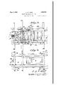
- Figure 1 is a view in side elevation of an apparatus constructed in accordance with the present invention.
- Figure 2 is a top plan view.
- Figure 8 is a bottom plan view.
- Figure 4 is a vertical, longitudinal sectional view taken on line 4-4, Figure 2, and looking in the direction of the arrows.
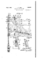
- Figure 5 is a viewin front elevation.
- Figure 6 is a transverse sectional view taken on line 66, Figure 1, and looking in the direction of the arrows.
- Figure 7 is a fragmentary, perspective view of the apparatus showing particularly the rocking frame.
- Figure 8 is an enlarged, fragmentary, see- 1931. Serial No. 554,314.
- Figure 9 is a fragmentary, perspective view of the breast plate showing one of the auxiliary brackets attached thereto.
- 1 designates the fence; by the term fence, I mean a suitable support or enclosure for the co-operating parts of my apparatus, and, therefore, the word is used in a broad sense, not limiting me to the arbitrary showing in the oflicial drawings.
- a movable platform 3 upon which the horse or cattle stands when drinking.
- a suitable container or tank 4 is placed on the front portion of the fence 1.
- a vertical well casing'o is fastened to the front of the fence and this casing is provided with a dischar e outlet 6, opening into the tank 4, Fig. 4.
- casing 5 is a vertically movable pump rod 7, which connects to suitable pumping means mounted in the container 8, whereby when the pump rod 7 is operated, water will be discharged through outlet 6 into the tank 4.
- a rocking frame 9 is mounted upon rod 10; rod 10 is journalled in suitable bearing plates 11 fixed to the upper portion of fence 1.
- This rocking frame comprises sides 12 in which are formed horizontal apertures 13.
- To the forward end of frame 9 is attached a vertical curved head -14.
- This head 14 is provided with a deep groove 15 (Fig. 4) for receiving links of chain 16.
- Chain 16 is held at its upper end by cotter pin 17 in connection with head 14.
- the lower end of chain 16 is connected by cotterpin 18 to the upper end of pump rod 7.
- On pump rod 7 is mounted a suitable counterbalance weight 19 for the purpose hereinafter described.
- a breast plate 20 is provided; this plate is provided with a large elongated aperture 21 through which the animal extends its head and neck to enable it to drink out of the tank 4, with its breast or shoulders pressing upon plate 20.
- the shaft 10 has sets of blocks 22 carried thereby and the upper endof breast plate 20 is fastened by bolts 23 to said blocks 22, whereby the breast plate moves synchronously with the rocking frame 9.
- Brace rods 24 are fastened at their upper outer ends by bolt 25 and cotter pins 26 to the forward end of rocking frame near the head 14.
- the lower inner end of each rod 24 is bifurcated and link 30 is mounted on rod .31; rod31 is car-:
- Cotter pins 32 are mounted on the ends of rod 31 to hold the upper ends of the links 30 in position. It is to be noted. that each link at its upper end is providedwith a plurality of aligned apertures 33, so that the rod 32 can be placed indifferent apertures for obtaining the desired accurate adjustment.
- Arod 34 is placed beneath the platform 3 in any one of a set of registering apertures 35. Therefore, it will be seen that if a greater leverage is desired, the rod 34 is placed inthe innermost-set of apertures 35, as shownin'Fig. 1, but if-less leverage is desired,- it can be moved forward to the desired'set.
- the weight 19 together with the weight of the pump. rod 7 is suflicient for pulling down on the head 14: and causing the inner end of the platform to be held in its raised position as shown, with the breast plate 20 extending outwardly as shown,
- bracing rods 24 produce an efficient apparatus in that they allow part of the pressure-strain to be distributed through them to the head 14,'for lifting the pump rod 7, 7 It will, therefore, be seen that by adjusting the ends of links 80 with respect to the rocking frame 9 andthe hinged platform 3, the leverage caused by the animal walking upon the platform canbe adjusted to a nicety. Further, the breast plate is adjustable, by changing the positions of the bifurcated ends of brace rods 20 upon the auxiliary brackets 27, attached to the inner face of the breast plate 20. I Y
- Every other link of chain 16 extends into the roove 15, thereby guiding the chain on the head as the head swings upwardly and downwardly, causing the pump rod 7 to have a true centeringor alignment'within the caslng 5. 5
- he pumping mechanism at 8 can be of stif ficientsize to cause sufficient water to flow into the tank 4 at'one stroke of the pump the platform, causing the pump rod 7 which stroke is caused by the animal taking its position on the platform and against the breast plate.
- the apparatus is provided with suitable runners 36 for enabling it to be hauled easily over the ground.
- a suitable overflow pipe 37 is provided, whereby water will not run over the edges of the tank.
Landscapes
- Life Sciences & Earth Sciences (AREA)
- Environmental Sciences (AREA)
- Animal Husbandry (AREA)
- Biodiversity & Conservation Biology (AREA)
- Structures Of Non-Positive Displacement Pumps (AREA)
Description
J. A. F OSSE 1,856,582
GRAVITY AND FORCE STOCK PUMP May 3, 1932.
Filed July 31, 1931 4 Sheets-Sheet l 3f $1 9.1, Z6 21 5 H6 A4 I V O 1 24 1a 50 J8 O 19 I Q90 5 7 9 Q 9 E; k o w 0 0 4 0 29 O a 2] j 3 7 4 "1': v lliilllliill (a u 'I I I LI R 1' 99 y ||||||||||||h ATTORNEYS.
mum!mlllllllllllllllllllll A ay M Y$2 b w fi M 1932. J. A. Posse GRAVITY AND FORCE STOCK PUMP Filed July 31, 1931 4 Sheets-Sheet 5 2 ATTORNEYS.
May 3,1932. 0555 1,856,582
GRAVITY AND FORCE STOCK PUMP Filed July 31, 1931 4 Sheets-Sheet ,4
INVENTOR. ET. A-F'Osse. W
)1 TTORNEYS.
Patented May 3, 1932 UNITED STATES JOHANES A. F. OSSE,
OF SHELDON, IOWA.
GRAVITY AND FORCE STOCK PUMP Application filed July 31,
This invention relates to a gravity and force stock pump.
An object of the invention is the construction of an apparatus to eliminate the necessity of filling water tanks or troughs by hand windmills or otherwise, and providing efficient means for filling asmall tank or trough with fresh water by the automatic operation of a-pump when the stock approaches the tank.
Another object of the invention is the provision of means operated by the weight of an animal together with the force or pressure of the animal to pimp or elevate water for the animal to drink.
7 A still further object of the invention is the construction of a fence-enclosed movable platform, a movable breast plate contiguous to said platform, a pump unit contiguous to said platform and breast plate, and means connecting said pump unit, platform and breast plate, whereby when weight is placed upon the platform and pressure is exerted upon said breast plate, said pump unit will be actuated.
With the foregoing and other objects in view, my invention comprises certain novel constructions, combinations and arrangements of parts as will be hereinafter fully described, illustrated in the accompanying drawings, and more particularly pointed out in the appended claims.
In the drawings:
Figure 1 is a view in side elevation of an apparatus constructed in accordance with the present invention.
Figure 2 is a top plan view.
Figure 8 is a bottom plan view.
Figure 4 is a vertical, longitudinal sectional view taken on line 4-4, Figure 2, and looking in the direction of the arrows. Figure 5 is a viewin front elevation.
Figure 6 is a transverse sectional view taken on line 66, Figure 1, and looking in the direction of the arrows.
Figure 7 is a fragmentary, perspective view of the apparatus showing particularly the rocking frame.
Figure 8 is an enlarged, fragmentary, see- 1931. Serial No. 554,314.
tional view showing how the breast plate is mounted.
Figure 9 is a fragmentary, perspective view of the breast plate showing one of the auxiliary brackets attached thereto.
Referring to the drawings by numerals, 1 designates the fence; by the term fence, I mean a suitable support or enclosure for the co-operating parts of my apparatus, and, therefore, the word is used in a broad sense, not limiting me to the arbitrary showing in the oflicial drawings. Mounted upon rod 2 1s a movable platform 3, upon which the horse or cattle stands when drinking. A suitable container or tank 4 is placed on the front portion of the fence 1. A vertical well casing'o is fastened to the front of the fence and this casing is provided with a dischar e outlet 6, opening into the tank 4, Fig. 4. casing 5 is a vertically movable pump rod 7, which connects to suitable pumping means mounted in the container 8, whereby when the pump rod 7 is operated, water will be discharged through outlet 6 into the tank 4.
A rocking frame 9 is mounted upon rod 10; rod 10 is journalled in suitable bearing plates 11 fixed to the upper portion of fence 1. This rocking frame comprises sides 12 in which are formed horizontal apertures 13. To the forward end of frame 9 is attached a vertical curved head -14. This head 14 is provided with a deep groove 15 (Fig. 4) for receiving links of chain 16. Chain 16 is held at its upper end by cotter pin 17 in connection with head 14. The lower end of chain 16 is connected by cotterpin 18 to the upper end of pump rod 7. On pump rod 7 is mounted a suitable counterbalance weight 19 for the purpose hereinafter described.
A breast plate 20 is provided; this plate is provided with a large elongated aperture 21 through which the animal extends its head and neck to enable it to drink out of the tank 4, with its breast or shoulders pressing upon plate 20. The shaft 10 has sets of blocks 22 carried thereby and the upper endof breast plate 20 is fastened by bolts 23 to said blocks 22, whereby the breast plate moves synchronously with the rocking frame 9. Brace rods 24 are fastened at their upper outer ends by bolt 25 and cotter pins 26 to the forward end of rocking frame near the head 14. The lower inner end of each rod 24 is bifurcated and link 30 is mounted on rod .31; rod31 is car-:
ried in registering apertures 13 of ,rocking frame 9. Cotter pins 32 are mounted on the ends of rod 31 to hold the upper ends of the links 30 in position. It is to be noted. that each link at its upper end is providedwith a plurality of aligned apertures 33, so that the rod 32 can be placed indifferent apertures for obtaining the desired accurate adjustment. Arod 34 is placed beneath the platform 3 in any one of a set of registering apertures 35. Therefore, it will be seen that if a greater leverage is desired, the rod 34 is placed inthe innermost-set of apertures 35, as shownin'Fig. 1, but if-less leverage is desired,- it can be moved forward to the desired'set. The weight 19 together with the weight of the pump. rod 7 is suflicient for pulling down on the head 14: and causing the inner end of the platform to be held in its raised position as shown, with the breast plate 20 extending outwardly as shown,
ready for an animal to w'alk upon the plat- 7 form and project itshead through opening a pressure 21, whereby,as it drinks,it will be exerting on the breast plate, as.well as a weight on rod-7 to be lifted, resulting in the discharge of water into trough 4:. The bracing rods 24 produce an efficient apparatus in that they allow part of the pressure-strain to be distributed through them to the head 14,'for lifting the pump rod 7, 7 It will, therefore, be seen that by adjusting the ends of links 80 with respect to the rocking frame 9 andthe hinged platform 3, the leverage caused by the animal walking upon the platform canbe adjusted to a nicety. Further, the breast plate is adjustable, by changing the positions of the bifurcated ends of brace rods 20 upon the auxiliary brackets 27, attached to the inner face of the breast plate 20. I Y
Every other link of chain 16 extends into the roove 15, thereby guiding the chain on the head as the head swings upwardly and downwardly, causing the pump rod 7 to have a true centeringor alignment'within the caslng 5. 5
' T he pumping mechanism at 8 can be of stif ficientsize to cause sufficient water to flow into the tank 4 at'one stroke of the pump the platform, causing the pump rod 7 which stroke is caused by the animal taking its position on the platform and against the breast plate.
The apparatus is provided with suitable runners 36 for enabling it to be hauled easily over the ground. I
A suitable overflow pipe 37 is provided, whereby water will not run over the edges of the tank.
Therefore, itwill be seen that I have shown in thepreferred embodiment of my invention, illustrated-in the official drawings, an apparatus in which the combined weight of an animal and itspressing upon a unit results in a greater pumping action be obgained than has ever been obtained hereto:
ore. I
While I have 'describedthe preferredembodiment of my invention and illustrated the same in theaccompanying drawings, certain minor changes or alterations may appear to one skilled in the art to which this invention relates during the extensive manufac ture of the same, and I, therefore, reserve the right to make such alterations or changes as shall fairly fall within the scope of the appended claims. is V WhatI claim is:
1. In an apparatus of the class described, the combination with a fence, of amovable platform therein, a movable breast plate carried by said fence, a pump unit, and means connecting said pump unit, platform and breast plate, whereby when weight is placed upon said platform and pressure is exerted against said breast plate, said pump unit will be actuated. r
2. In an apparatus of the class described, the combination with a fence, a pump unit contiguous to. said fence, a movable platform within said fence, of a rocking frame on said fence, a breast plate provided with a central opening onsaidframe, means adjustably connecting said breast plate to said rocking frame, means connecting said rock- .a ing frame to said pump unit, and means connecting said rocking frame to said platform.
3. In an apparatus of the class described, the combination with a fence, a pump unit contiguousto said fence, a movable platform within said fence, of a rocking frame on said fence, a breast plate on said fence and extending downwardly over said platform, said breast plate provided with brackets, brace rods connected at their upper ends 7 to said rocking frame and at their lower ends to said brackets, means connecting said rocking frame to said pump unit, and means connecting said rocking frame to said platform. 1. In an apparatus of the classdescribed, the combination with a fence, a pump unit contiguous to said fence, of a rocking frame on said fence, a platform onsaid fence, a breast platecarried by said frame'above said platform, brackets attached to the inner face of said breast plate, rods connected at their upper ends to said rocking frame and straddling at their lower ends said brackets, means fastening said straddling ends and brackets together, means connecting said rocking frame to said pump unit, and means connecting said rocking frame to said platform.
In testimony whereof I hereunto afiix my signature.
JOHANES A. F. OSSE.
Priority Applications (1)
| Application Number | Priority Date | Filing Date | Title |
|---|---|---|---|
| US554314A US1856582A (en) | 1931-07-31 | 1931-07-31 | Gravity and force stock pump |
Applications Claiming Priority (1)
| Application Number | Priority Date | Filing Date | Title |
|---|---|---|---|
| US554314A US1856582A (en) | 1931-07-31 | 1931-07-31 | Gravity and force stock pump |
Publications (1)
| Publication Number | Publication Date |
|---|---|
| US1856582A true US1856582A (en) | 1932-05-03 |
Family
ID=24212889
Family Applications (1)
| Application Number | Title | Priority Date | Filing Date |
|---|---|---|---|
| US554314A Expired - Lifetime US1856582A (en) | 1931-07-31 | 1931-07-31 | Gravity and force stock pump |
Country Status (1)
| Country | Link |
|---|---|
| US (1) | US1856582A (en) |
Cited By (2)
| Publication number | Priority date | Publication date | Assignee | Title |
|---|---|---|---|---|
| US2891509A (en) * | 1959-01-02 | 1959-06-23 | Utina Electrowerk G M B H | Watering device for stock |
| US20030056732A1 (en) * | 2001-08-31 | 2003-03-27 | Anderson James H. | Livestock watering method and apparatus |
-
1931
- 1931-07-31 US US554314A patent/US1856582A/en not_active Expired - Lifetime
Cited By (3)
| Publication number | Priority date | Publication date | Assignee | Title |
|---|---|---|---|---|
| US2891509A (en) * | 1959-01-02 | 1959-06-23 | Utina Electrowerk G M B H | Watering device for stock |
| US20030056732A1 (en) * | 2001-08-31 | 2003-03-27 | Anderson James H. | Livestock watering method and apparatus |
| US6776121B2 (en) * | 2001-08-31 | 2004-08-17 | James H. Anderson | Livestock watering method and apparatus |
Similar Documents
| Publication | Publication Date | Title |
|---|---|---|
| NO121293B (en) | ||
| US1856582A (en) | Gravity and force stock pump | |
| CN106568301A (en) | Fodder drying device | |
| US1973803A (en) | Elevating apparatus | |
| US1680722A (en) | Fish elevator | |
| US2267705A (en) | Oil field apparatus | |
| US2234366A (en) | Animal holder | |
| CN104326281A (en) | Live fish transfer device and live fish transfer method | |
| US2691958A (en) | Wind oriented livestock dispenser | |
| CN106305485A (en) | Scientific detection device for pregnant sows | |
| US1805376A (en) | Seed potato cutter | |
| US1300021A (en) | Automobile camp-trailer. | |
| US36203A (en) | Improvement in cattle-pumps | |
| US1712613A (en) | Chicken feeder and exerciser | |
| US33201A (en) | Improvement in flood-gates | |
| US1325035A (en) | Automatic calf-feeder | |
| US1455626A (en) | Water pump | |
| DE407908C (en) | Pneumatic teat cup | |
| US1569238A (en) | Clothesrack | |
| US1910519A (en) | Portable mill | |
| GB325325A (en) | Cage for sows with sucking pigs | |
| US1976633A (en) | Pumping jack | |
| DE479596C (en) | Acid lifter | |
| US1525366A (en) | Hog-ringing crate | |
| US3064656A (en) | Hydraulic lift for corn sheller feeder |