US1856498A - Conveying mechanism - Google Patents
Conveying mechanism Download PDFInfo
- Publication number
- US1856498A US1856498A US202629A US20262927A US1856498A US 1856498 A US1856498 A US 1856498A US 202629 A US202629 A US 202629A US 20262927 A US20262927 A US 20262927A US 1856498 A US1856498 A US 1856498A
- Authority
- US
- United States
- Prior art keywords
- carriers
- slack
- conveyor
- sections
- sprockets
- Prior art date
- Legal status (The legal status is an assumption and is not a legal conclusion. Google has not performed a legal analysis and makes no representation as to the accuracy of the status listed.)
- Expired - Lifetime
Links
- 230000007246 mechanism Effects 0.000 title description 14
- 239000000969 carrier Substances 0.000 description 77
- 241001584775 Tunga penetrans Species 0.000 description 13
- 239000012141 concentrate Substances 0.000 description 6
- 230000000153 supplemental effect Effects 0.000 description 6
- 239000000463 material Substances 0.000 description 4
- 230000004048 modification Effects 0.000 description 3
- 238000012986 modification Methods 0.000 description 3
- 230000010355 oscillation Effects 0.000 description 3
- 230000005484 gravity Effects 0.000 description 2
- 210000003739 neck Anatomy 0.000 description 2
- 239000002994 raw material Substances 0.000 description 2
- 235000015842 Hesperis Nutrition 0.000 description 1
- 235000012633 Iberis amara Nutrition 0.000 description 1
- 238000010521 absorption reaction Methods 0.000 description 1
- 230000001133 acceleration Effects 0.000 description 1
- VREFGVBLTWBCJP-UHFFFAOYSA-N alprazolam Chemical compound C12=CC(Cl)=CC=C2N2C(C)=NN=C2CN=C1C1=CC=CC=C1 VREFGVBLTWBCJP-UHFFFAOYSA-N 0.000 description 1
- 229910052729 chemical element Inorganic materials 0.000 description 1
- 210000005069 ears Anatomy 0.000 description 1
- 230000002452 interceptive effect Effects 0.000 description 1
- 238000004519 manufacturing process Methods 0.000 description 1
- 229920000136 polysorbate Polymers 0.000 description 1
- 230000000979 retarding effect Effects 0.000 description 1
- 238000007665 sagging Methods 0.000 description 1
- 238000007493 shaping process Methods 0.000 description 1
- 230000001360 synchronised effect Effects 0.000 description 1
- 239000002023 wood Substances 0.000 description 1
Images


Classifications
-
- B—PERFORMING OPERATIONS; TRANSPORTING
- B65—CONVEYING; PACKING; STORING; HANDLING THIN OR FILAMENTARY MATERIAL
- B65G—TRANSPORT OR STORAGE DEVICES, e.g. CONVEYORS FOR LOADING OR TIPPING, SHOP CONVEYOR SYSTEMS OR PNEUMATIC TUBE CONVEYORS
- B65G23/00—Driving gear for endless conveyors; Belt- or chain-tensioning arrangements
- B65G23/24—Gearing between driving motor and belt- or chain-engaging elements
- B65G23/30—Variable-speed gearing
Definitions
- This invention relates'to conveying mechanism, and an object ofthe same is to provide an improved form of conveyor of the flexible endless, type embodying a .predetermined amount of slack and traversing or moving adjacent a stationar frame having fabricating units mounted t ereon, the conveyor as a whole being driven continuously from a suitable source of power and at the same 1 time having the slack concentrated in sections thereof so that certain portions of the conveyor may be periodically or intermittently halted or rendered inert for fabricating operations while the slack is being distributed, the sections then being accelerated and moving forward as a part of the conveyor in regular order, thus eliminating the necessity of intermittent stopping and starting of the entire conveyor with consequent consumption of power spent in acceleration and retardation.
- Another object of the invention is to provide a continuously driven conveyor of the endless type embodying a predetermined degree of distributed slack and means for isolating the slack and periodically or intermittently accumulating or concentrating the isolated slack in sections and subsequently i e-distributing the concentrated slack, to
- a further object of the invention is to eliminate the necessity .of providing means for imparting a 'step-by-step movement to an endless conveyor or clutch mechanism or ashiftable frame in the mechanism cooperating therewith or supporting the conveyor,
- a further object of the. invention is to construct a continuously drivenconveyor of the type described, which may be intermittently arrested at certain positions, which conveyor can be adapted for use inpottery, plastic working, wood working, and other affecting the continuous drive 7 1927.
- fabricating units are mounted on a slidable frame in turn supported by a main frame so that they may move forward with the conveyor during a fabricating operation and then back again, while in the present instance the fabricating units are shown stationarily mounted on the main supporting frame, the present invention being utilized to provide for temporarily halting sections of the conveyor for fabricating operations on the molds without afiecting the continuous drive of the conveyor, thereby saving power which would otherwise be spent in accelerating and retarding a slidable frame bearing the fabricating units.
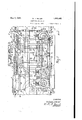
- Figure 1 is a fragmentary view in side elevation of a conveyor embodying the features of the invention shown applied to a pottery fabricating machine;
- Fig. 2 is a' section, partly broken away
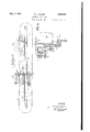
- Fig. 3 is a fragmentary detail view in side elevation of a part of theconveyor showing one phase of operation;
- Fig. 4 is a similar view of a modification in structure in another phase of operation
- Fig. 5 is a similar view of a further slight 1 modification in'structure
- Fig. 6 is an enlar ed detail sectional view on the line VIVI, ig. a;
- Fig. 7 is a view similar to Fig. 3, showing another phase of operation of the conveyor;
- Fig. 8 is an enlarged sectional view on the vliine VIIIVIII, Fig. 4;
- FIG. 9 is a diagrammatic side elevation of a conveyor, illustrating a numb'erof different Y applicationsof the-invention.
- the main stationary supporting frame for the conveyorand operating parts is generally indicated at 11 and is shown as having adjustably connected thereto as by-screws 11" sta-' I ltionary jigger frames 89, which have slidably connected thereto vertically.
- disposed,- hollow reciprocating jigger spindles12 by means of stationary vertical spindles 90, which telescope into and are in spline-sliding engagement with said jigger spindles 12, the latter having secured thereto horizontally-disposed friction gears 13, adapted to intermittently V mesh with vertically disposed friction gears 8 tating sprockets to bring the pallets and molds 14.
- the spindles 12 are shown as terminating 1 at their upper ends in chucks 15, tointermittently raise molds 50 from pallets or carriers 16, adapted to be conveyed by a conveyor 17 the latter being actuated by continuously rointo operative position under profiles 18 and under feeders and preformers 19', as will be hereinafter more fully described.
- a power shaft 20 is shown as horizontally mounted in pairs of bearings 21, 22 and 23, this shaft serving toprimarily reciprocate the spindles 12 and impart motion to the conveyor 17, as
- Rotary motion is imparted-t0 the jigger spindles 12 with the molds 50 thereon by means of said gears 13 and 14, the latter being secured A to shafts 91, which may be actuated independently of each other by suitablemoto'rs.
- a worm 24 isshown in Fig. 1 as positioned between the pair of bearings 22 and secured to the shaft 20 in mesh with a worm gear 25 which is enclosed by a housing 26, which is shown as secured to the frame 11 by means of suitable fastenings.
- the gear 25 is secured to a shaft 27, whlch has adpistably secured thereto one-or more vcams 28 for actuating one or more levers 29,
- Patent N 1,655,431.
- Another worm 40 is secured to the shaft 20 and positioned between the pairs of bearings 21 in mesh with a worm gear 41, which is posi tioned in the'same plane with the gear 25 and is indicated in Fig. 1 by its pitch circle in-dot and dash lines.
- the gear 41 is secured to a shaft 42, which has also adjustably secured thereto one or,
- a third worm 52 is secured to the shaft 20 r and positioned between the pair of bearings 23, in mesh with avworm gear 53, which is positioned in the same plane with the ears haft 54 has secured thereto a pinion 55, in mesh with a spur gear 56, which is secured to a spr0cket58, in mesh with a chain 59, which extends to another sprocket 60, which is secured to a shaft 61 and transmitsthereto motion from the shaft 57.
- The. latter serves to. synchronize the rotation of sprockets 62 and 88 for the purpose of establishing and V adjustably maintaining a predetermined "amount ofslack in the conveyor between the sprockets 62 and 88 for a more fully described.
- the shafts 5 7 and purpose hereinafter 61- have also secured .105 shaft 57, the latter having secured thereto a theretoeach a pair of sprockets 62 and 88 respecti'vely, in mesh with the chains of the conveyor 17 which may extend as more fully shown in Fig. 9 through a,considerable-distance in a direction to the right of he sprockets 88 or to the left of the sprocke 62, and pass through suitable treating means 7 (not shown), such as dryers, at the left of the sprockets 62, and preliminary treating means at the right of the sprockets '88.
- each of the pallets or carriers 16 is below the level of the trunnions 63 thereof, whereby the pallets or carriers 16 are always maintained in a substantially horizontal position and with their centers of gravity in substantially the same vertical planes with their trunnions 63.
- the shaft 54 has also secured thereto a sprocket 64, in mesh with a chain 65, which extends to and is in mesh with another sprocket 66, the latter being secured to an overhead spindle 67, which actuates a number of the profiles 18, preferably arranged in a line transversely to the conveyor 17.
- the spindle 67 has also secured thereto a sprocket 92, operativelyconnected by. means of a chain 93 to another sprocket 94:, the latter being secured to another spindle 95, which preferably actuates a line of feeders and preformers 19, also arranged transversely to the conveyor 17.
- Additional sprockets similar to 92 may be employed with chains, similar to 93, ther on, to transmit motion to additional sprockets and spindles, similar to 9 and 95 respectively, to actuate one or more lines of fabricating units or tools which may be other than feeders and preformers or jiiggers if desired.
- the trunnions 63 have swiveled thereon sleeves 97, which have thereon grooved enlargements or heads 86, as shown in Fig. for a purpose, which is hereinafter described.
- the sleeves 97 may have their ends secured to the ends of the carriers 16 in any suitable manner.
- Rolls 68 are swivelled on the sleeves 9 and ride on a pair'of rails 69, which are mounted on the frame 11, one on each side of the carriers 16.
- the chains of the conveyor 17 are shown in Figs. 3, 4 and 5 as having thereon each a group of links 70 between each consecutive two carriers 16.
- the links 7 O are pivotally connected to each other by means of pins 71 and 71a intermediate of the trunnions 63; each middle pin 71a being preferably provided with one or more enlargements, such as a pair of washers or rolls 72, which cause the pins 71a to be initially raised in position above the level of the pins 71 on rails 96, when the links 70 are collapsed into a semiplzli-ntographic shape, as is hereinafter more llydescribed, whereupon the pins 71 and 71a are lowered onto a pair of the rails 96,
- the length of the chains of the conveyor 17 between the pair of sprockets 62 and the next pair of sprockets 88, to the right thereof, as shown in the drawings, is made excessive to allow a certain amount of slack thereon between the tops of the s rockets 62 ereinafter described.
- This slack may be utilized for periodically halting those of the carriers 16 which are situated over the chucks 15, the carriers being temporarily locked in position by means of the hook ends 75 of a pair of latches 7 3,, adjustable as to length while the pivotal connection subsists or while in operation through the medium of screws 73*, the carriers being thus temporarily halted and maintained in stable position without stopping the sprockets 62 and 88.
- the latches 73' may be positioned in openings in the rails 96 and pivotally connected to the rails 69 at 74 and are so balanced as to have their hook ends 75 normally extending upwardly to intercept the grooved head 86 of the sleeves 97 on the trunnions 63 of the carriers 16 which pass over the hook ends 75 and keep the carriers stationary untif.
- the latches 73 are disengaged from the heads86 by means of pins 76 carried by a pair of oscillating arms 77, hereinafter described, and cams 78 on the underside of the latches 73, adapted to be intermittently engaged by said pins 7 6.
- the hook ends 7 5 of the latches 73 may be given a ll-shape substantially similar to the groove in the head 86, so that when the said hook ends engage the said heads, (see Fig. 8) the carriers or trays will be centered laterally at the operating point, or in the present instance when the chucks rise through the mold seats or re Completes in the carriers.
- the latches 73 may be adjusted laterally while in operation or while the pivotal connection subsists through the medium of lock nuts 7 4* on the pivot bolt 74, Fig. 8, and the tracks 69 may also be adjusted laterally as by interposing shims 69 between the track and frame 11 and vertically as by enlarged openings 69 through which screw 69 passes.
- the sleeves 97 may 'be threadedthrough the carriers or trays 16 and thus provide independent lateral adjustment of said trays, a set screw 97 extending into the carrier and abutting against said sleeves to maintain the latter in adjusted position.
- the enlarged heads 68 are preferably given lateral play as shown in Fig. 6, to permit the latches 73 to function as a centering means and also to ensure free running of the carriers at all points. If desired the shaped or analogous contours;
- rollers or heads 68 may also be made to function as a centering means for the carriers by eliminating the lateral play on the sleeves '97 and providing the contacting surfaces of the tracks 69 an the rollers or heads with V- be shifted in position lengthwise of the arms 77, a slight'irregularity of motion being introduced by the outline of the slot 98 in the arms 77, which have pivotally connected thereto at81 a pair of rolls 82, which are engaged by a pair of positive cams 83, adjustably mountedon the shaft 42 as by hubs 83 and screws 83", whereby the arms 77 are oscillated.
- the arms 77 have pivotally connected thereto at the upper ends thereof by means of pins 87 a pair of adjustable pawls, which consist each of two parts, 84 and 85, adjustably connected as by means of thread-bolts 4 of the drawings causes the arms '77 to engage the cams 8, thereby reand screws 84 as shown, enabling adjustment as to length without disconnecting or while in operation.
- Thepawls 84-85 may be adjusted laterally as by interposed shims 85, see Fig. 6.
- the awls 84 85 may thenbe movedby the arms 7 through a space equal'to the 'distance'beeratween the centers of the extreme carriers 16 I of said line.
- This motion of the pawls 84-85 will cause the links between the trlmnions 63 of the carriers 16 of the conveyor 17 to be gathered up ahead of the said pawls, or to the. left in Figs/1 and 7 of the drawings, into a semi antog'raphic form as shown in Figs. 4 and where the chains of the conveyor 17 pass over the rails 96, and
- the carrier 16 which is positioned under the line of profiles-18 transversely to the chains of the conveyor 17 is moved to the left in Figure 1 after the operation of shaping the material on the molds carried by this carrier has been completed by said profiles, and the next carrier 16 to the right which is positioned under said feeders and preformers .19 is moved into position under the profiles 18 after a charge of material has been fed to the molds on this carrier and preformed, and simultaneously another carrier with molds thereon is" moved into position under the feeders and preformers 19.
- the latches 73 are brought into action to engage the trunnions 63 of the carriers 16 by means of the hook ends 7 5 on the latches 7 3 and the heads 86 of the sleeves 97 on the trunnions 63 and hold the carriers 16 under the profiles 18 and feeders'and preformers 19while the pawls 84-85 are moved through the greater part of their return stroke by V the oscillation. of the arms 77 in a direction from left to right in Fig. 1.
- the part of the chain of the conveyor 17 with the links-70 thereon which is situated to the left of the-profiles 18 in Fig. 1 has its slack gradually taken out of it by the continuous pulling action of-the sprockets 62 at the left hand end of Fig. 1 and may be brought to a substantially-straight shape as shown in Fig. 3 and at thesame; time that part of the conveyor chain 17 which issituated to the right of the preformers and feeders is gradually gathered up into a semipantograph ic shape as shown in Fig. 3 by the action of the sprockets 88 situated at the right hand end of'Fig.
- ap- Means for retaining the conveyor chains in mesh with the sprockets may be-provided in the form of tapered blocks 11 suitably secured to the frame 11.
- the jigger frames 89 are stationarily mounted on the means or frames for the feeders and pre-- formers and profiles, and material may be fed to the molds and preformed and shaped,-
- the point at which the motion of the various parts of the mechanism takes place may be accurately determined by the sundry adjustments heretofore described.
- the shaft 57 being the driving shaft of the conveyor and the shaft 61 the driven shaft
- this relation may be reversed, in which event the sprocket 88 may be made 7 the driving sprocket of the conveyor chain 17 instead of the sprocket 62 and the chain 59 with the sprockets 58 and 60 omitted and suitable means provided to keep the lower part of the conveyor from unduly sagging and pulling on the sprocket 62 such as atrack or idler sprockets under'the lower part of the chain, or a brake or other means applied to the sprocket 62 to prevent overrunning of the same. or a means may be provided for taking up the slack of the lower part of the chain'if desired.
- the pallets serve as a means, in add tion to carrying the molds 50, for operatively connecting the parallel chains of the conveyor; and it is. obvious that these pallets could be replaced by buckets or anv other form of device used in connection with flexible conveyors, and furthermore,- fiexible members other than chains could be employed as well as any desired form of motion-transmittmsz means other than the sprockets, the latter being shown simply to illustrate a driving means for the conveyor.
- Other means than the latches 73 may be used for holding the pallets 16 inert as well as other means than the pawls 8485 for movingsaid pallets, these devices simply being shown in the present instance for the pur poses of illustration.
- the conveyor could be mounted on mot ontransmitting means such as the sprockets herein referred to having either a horizontal or vertical axis without departing from the scope of the invention.
- Power may be primarily applied to the shaft 20 through the medium of a suitable motor or the like, rotary motion, vertical reciprocation and lateral reciprocation, re-
- the halted sections may be started in motion by the levers 77 or by the combined effort of the leversand drive sprockets or by the drive sprockets alone, depending upon the adjustment of the working stroke of said levers.
- the working stroke of the levers may be adjusted to advance a section at an accelerated speed and accumulate the slack in front of the saidsection and the latter remain inert until the continuous drive of the conveyor absorbs the slack and carries the section forward, or the stroke of the levers 77 may be adjusted .to advance the sections and accumulate a portion of the total slack, and
- the rotary elements or sprockets in this instance engaging the conveyor at one length only.
- the conveyor may be primarily driven from any of the rotary elements.
- the slack maybe isolated in sections and restricted to said sections and maintained constant therein.
- the conveyor mechanism previously described may be utilized in arts other than the manufacture of pottery.
- the carriers 16 may be replaced by buckets, molds, grippers, receptacles, 0r any other'mechanisms for holding the article or raw material to' be subjected to the working inch.
- a conveyor comprising spaced rotatable elements, normally taut endless flexible :members positively engaged by said rotatable ele-. ments, carriers mounted in series in said endless flexible members, said members being ini-' tially provided with slack sections between said elements and the latter rotated in synchronism to confine the slack-to said sections while the remaining portion of said flexible members remains taut, and a supplemental intermittent drive means for advancing the carriers in the slack sections of said flexible members at a speed in excess of the remain- 2.
- a conveyor comprising one or moreof spaced sprockets, an endless chain positively engaged by saidsprockets, carriers mounted in series in said chain, said chaim.
- a conveyor comprising endless flexible members, rotatable elements which positively engage said flexible members, said elements beingspaced a certain distance apart to provide a predetermined amount of sl'a'ck in said flexible members therebetween and continuously rotated in synchronism to isolate the slack in sections while the remaining portion of said flexible members remains taut, and a supplemental intermittent driving means mounted to-act on one or more sections of said flexible members between said elements for periodically advancing said sections at a speed in excess of the normal travel of said flexible members.
- a conveyor comprising endless flexible members having carriers mounted in series therein, .said' flexible'members being positively engaged by rotatable elements spaced a Vpi'edetermined distance apart to provide a predetermined amount of slack therebetween and-continuously driven in synchronism to maintain the amount of slack constant, a supporting track between said elements over which said carriers have movement, and
- I means acting longitudinally of said flexible members between said elements for periodically advancing one or more of said carriers at aspeed in excess of the normal travel of the remainder of'said carriers to concentrate the slack andthereby permit certain ofthe carriers to remain inert while the slack is being distributed by the continuously driven elements.
- cam and-lever means acting longitudinally of said' flexible members between said elements forperiodically advancing one or more of said carriers at a speed in excess of the remainder of said carriers to concentrate the slack and thereby permit certain of the carriers to remain inert while the slack is being distributed by the continuously rotating elements.
- a conveyor comprising endless flexible members having carriers mounted in series therein, said flexiblemembersbeing positively engaged by rotatable elements spaced a predetermined distance apart .to provide a predetermined amount of slack therebetween and continuously driven in synchronism to maintain the amount of slack constant, means for periodically advancing oneor more of said carriers at a speed in excess of the remainder of said carriers to concentrate the slack and thereby permit certain of the carriers to remain inert while the slack is being distributed by the continuously driven elements, and means for automatically alternately gripping and releasing the inert carriers during concentration and distribution of the slack.
- a conveyor comprising spaced rotatable elements, normally taut endless flexible mem-i bers positively engaged by said rotatable ele-' ments, carriers mounted in series in saidendless flexible members, said members being 1n1t1ally provlded with slack sectlons between said elements and the latter rotated in synchronism to confine the slack-' to said sections While the remaimng portion of said flexible members remains taut, a supplemental inter- -mittent drive means for advancing the carriers in the slack sections of said flexible members at a speedin excess of the rema1ning carriers to permit said carriersto remain temporarily at rest for a fabricating operatron, and means for locking said carr ers 1n the position of rest.
- a conveyor comprising spaced rotatable elements, normally taut endless flexible members positively engaged by said rotatable elements, carriers mounted vin series in said endless flexible members, said members being 1 initially provided with slack sections between said elements and the'latter rotated in synchronism to confine the slack to said sections while the remaining portion of said flexible members remains taut, a supplemental inter- Gil mittent drive meansfor advancing the carriers in the slack sections of said flexible members at a speed in excess of the remaining carriers to permit said carriers to remain temporarily at rest fora fabricating operation, means for locking said carriers in the position of rest, and means for releasing said locking means.
- a conveyor comprising endless flexible members having carriers mounted in series therein, said flexible members being positively engaged by rotatable elements spaced apredetermined distance apart to provide a. predetermined amount of slack therebetween and continuously driven in synchronism to maintain the amount of slack constant, means for periodically advancing a definite number of said carriers at a speed in excess of the remainder of said carriers to concentrate the slack and therebypermit certain of the carriers to remain inert While the slack is being distributed by the continuously driven elements, means for automatically gripping the inert carriers to hold them in stable position. and means operating in conjunction with said carrier-advancing means for automatically releasing said gripping means.
- a conveyor comprising endless flexible members having carriers mounted in series therein, said flexible members being positively engaged by rotatable elements spaced a predetermined-distance apart to provide a predetermined amount of slack therebetween and. continuously driven in synchronism to v maintain the amount of slack constant, means predetermined distance apart to provide a predetermined amount of slack therebetween and rotated in synchronism to maintain the slack constant, and a means for isolating the slack in sections between said rotatable ele ments.
- a conveyor comprising s aced rotatable elements, normally taut en less flexible iio members positively engaged by said rotatable elements carriers mounted in series in said endless flexible members, said members being initially provided with slack sections between 5 said elements and the latter rotated in synchronism to confine the slack to saidsections while the remaining portion of said flexible members remains taut a supplemental intermittent drive means for advancing the car- 1o riers inthe slack sections of said flexible members at aspeedin excess of the remaining carriers, and means for supporting said carv riers while in said slack sections.
- a conveyor comprising one or more 15 pairs of spaced sprockets, an endless chain positively engaged by said sprockets, carriers mounted in series in said chain, said chain beinginitially provided with slack between the sprockets and the latter rotated in syn go chronism to'confine the slack to that portion of the chain traveling between said sprockets 7 while the remaining portion of the chain remains taut, means operating between said sprockets for advancing certain of the'car- 2'5 riers at a speed in excess of the remaining carriers, and a track for supporting the carrierswhile traveling in .the sla'ckgportion of the chain. 7 I 17.
- a conveyor comprising spaced rotat- 80 able elements, endless flexiblemembers engaged by said rotatable elements, carriers mounted in series in said endless flexible members, said members being initially provided with slack sections between said elements and -95 the latter rotated in. synchronism to confine the slack to said sections while the remain ing portion of said flexible members remains taut, means for intermittently advancing c'ertain of the carriers between said elements at 40 aspeed in excess of the remaining carriers,
- A. con veyor comprising spaced rotatable elements, normally taut endless flexible v 6 members positively engaged byesaid rotatable elements, carriers mounted /in series in said endless flexible members, said members being initially provided with slack sections'between said elements and the latter'rotated in syn 80 chronism to confine the slack to said sections while theremainingportion of said flexible ;members remains taut a supplemental intermittent drive means for advancing the, carriers in the slack sections of said flexible members at a speed in excess of the remaining carriers to permit said carriers to remain tempo rarily at rest for a fabricating operation, and means for adjusting the position of rest of said carriers.
Landscapes
- Engineering & Computer Science (AREA)
- Mechanical Engineering (AREA)
- Treatment Of Fiber Materials (AREA)
Description
W. J. MILLER CONVEYING MECHANISM Filed June 50,
4 Sheets-Sheet l I I I I I I I IN VEA' 7' 0R ATTORNEY May 3, 1932. w. J. MILLER 1,856,498
CONVEYINGMECHANISM Filed June 30, 192? I 4 Sheets-Sheet 2 INVENTOR. ///dfl7 JMI/ler I BYK QIQM RNEY y 1932- w. J. MlLLER ,856,498
CONVEYING MECHANISM Filed June 30. 1927 4 Sheets-Sheet 3 l 6 W w 1 j w o i m? w 0 r h m w w o n 2 w J. w o u g 8 Q n 3 6 v5 W1. 0 H, o; F W M 0 AT w W Y WilZiamJIMiu ATTORNEY.
May 3, 1932- w. J. MILLER CONVEYING MECHANISM Filed June 30 1927 4 Sheets-Sheet INVENTOR.
WIHIDJH J. Mil/97 Patented May 3, 1932 WILLIAM J. MILLER, OF SWISSVALE, PENNSYLVANIA CQNVEYING MECHANISM j Application filed June 30,
This invention relates'to conveying mechanism, and an object ofthe same is to provide an improved form of conveyor of the flexible endless, type embodying a .predetermined amount of slack and traversing or moving adjacent a stationar frame having fabricating units mounted t ereon, the conveyor as a whole being driven continuously from a suitable source of power and at the same 1 time having the slack concentrated in sections thereof so that certain portions of the conveyor may be periodically or intermittently halted or rendered inert for fabricating operations while the slack is being distributed, the sections then being accelerated and moving forward as a part of the conveyor in regular order, thus eliminating the necessity of intermittent stopping and starting of the entire conveyor with consequent consumption of power spent in acceleration and retardation. 1
Another object of the invention is to provide a continuously driven conveyor of the endless type embodying a predetermined degree of distributed slack and means for isolating the slack and periodically or intermittently accumulating or concentrating the isolated slack in sections and subsequently i e-distributing the concentrated slack, to
thereby temporarily halt sections of the conveyor without thereof. k
A further object of the invention is to eliminate the necessity .of providing means for imparting a 'step-by-step movement to an endless conveyor or clutch mechanism or ashiftable frame in the mechanism cooperating therewith or supporting the conveyor,
' and particularly where the conveyor is re-. quired-to becomparatively long and heavy and support devices such as trays and molds which are required to be periodically and temporarily halted under or above or move adjacent fabricating or other units.
A further object of the. inventionis to construct a continuously drivenconveyor of the type described, which may be intermittently arrested at certain positions, which conveyor can be adapted for use inpottery, plastic working, wood working, and other affecting the continuous drive 7 1927. Serial No. 202,629.
*arts wherein articles or raw materials can be conveyed to the Working tools.
Other objects and advantages of the invention will'be apparent from a consideration of the drawings and description and appended claims.
For the purposes of illustration the invention is shown-as applied to pottery fabricating mechanism of a type substantially in accordance With the structure disclosed by my copending application for patent for automatic jigger and mold conveyor combined, .filed Jan. 6, 1927, Serial No. 159,395 which has become Patent N 0. 1,697,993. However, in my copending application just specified the fabricating units are mounted on a slidable frame in turn supported by a main frame so that they may move forward with the conveyor during a fabricating operation and then back again, while in the present instance the fabricating units are shown stationarily mounted on the main supporting frame, the present invention being utilized to provide for temporarily halting sections of the conveyor for fabricating operations on the molds without afiecting the continuous drive of the conveyor, thereby saving power which would otherwise be spent in accelerating and retarding a slidable frame bearing the fabricating units.
In the drawings:
Figure 1 is a fragmentary view in side elevation of a conveyor embodying the features of the invention shown applied to a pottery fabricating machine;
. Fig. 2 is a' section, partly broken away,
taken on the line 2-2, Fig. 1;
Fig. 3 is a fragmentary detail view in side elevation of a part of theconveyor showing one phase of operation; I
Fig. 4 is a similar view of a modification in structure in another phase of operation;
Fig. 5 is a similar view of a further slight 1 modification in'structure;
Fig. 6 is an enlar ed detail sectional view on the line VIVI, ig. a;
Fig. 7 is a view similar to Fig. 3, showing another phase of operation of the conveyor;
Fig. 8 is an enlarged sectional view on the vliine VIIIVIII, Fig. 4; and
9 is a diagrammatic side elevation of a conveyor, illustrating a numb'erof different Y applicationsof the-invention.
The main stationary supporting frame for the conveyorand operating parts is generally indicated at 11 and is shown as having adjustably connected thereto as by-screws 11" sta-' I ltionary jigger frames 89, which have slidably connected thereto vertically. disposed,- hollow reciprocating jigger spindles12 by means of stationary vertical spindles 90, which telescope into and are in spline-sliding engagement with said jigger spindles 12, the latter having secured thereto horizontally-disposed friction gears 13, adapted to intermittently V mesh with vertically disposed friction gears 8 tating sprockets to bring the pallets and molds 14. The spindles 12 are shown as terminating 1 at their upper ends in chucks 15, tointermittently raise molds 50 from pallets or carriers 16, adapted to be conveyed by a conveyor 17 the latter being actuated by continuously rointo operative position under profiles 18 and under feeders and preformers 19', as will be hereinafter more fully described. A power shaft 20 is shown as horizontally mounted in pairs of bearings 21, 22 and 23, this shaft serving toprimarily reciprocate the spindles 12 and impart motion to the conveyor 17, as
will also be more fully hereinafter described;
Rotary motion is imparted-t0 the jigger spindles 12 with the molds 50 thereon by means of said gears 13 and 14, the latter being secured A to shafts 91, which may be actuated independently of each other by suitablemoto'rs.
A worm 24isshown in Fig. 1 as positioned between the pair of bearings 22 and secured to the shaft 20 in mesh with a worm gear 25 which is enclosed by a housing 26, which is shown as secured to the frame 11 by means of suitable fastenings. V I
The gear 25 is secured to a shaft 27, whlch has adpistably secured thereto one-or more vcams 28 for actuating one or more levers 29,
which have pivotally connected thereto at one end thereof rolls :30 in contact with the cams 28, and at the other end thereof by means of ivots 33 the lower ends of pitmen 31, wh ch are slidably mounted sockets 32 in the frame 11. Y Y p v Each of the levers 29 is pivotally connected at 35 to a floating or shiftable pivot block 34,
' such. as described in my copending application for patent'fo'r multiple and automatic jigger, 'filed' Nov. 17, 1926, Serial-No. 148,872 which has become Patent No. 1,7 57,132, and whereby'the operative length of said levers 29 may be varied and adjusted while in operation'. 7 f- Forked yokes 36'are adjustably secured at one end thereof to the upper ends of the pitmen 31 by means of nuts 37 and 38 and are in engagement with necks 39 on some of the jigger spindles 12, to periodically raise the samei with some of the chucks 15 and molds 5 1) there '25 and 41, and is secured to a shaft 54.
on into operative position under the profiles 18, substantiallyas described in my copending application for patent for mechanism for producing intermittent rotation of a jigger spindle, filed Feb. 5, 1927, Serial No. 166,180,
which has become Patent N 0. 15,655,431.
Another worm 40 is secured to the shaft 20 and positioned between the pairs of bearings 21 in mesh with a worm gear 41, which is posi tioned in the'same plane with the gear 25 and is indicated in Fig. 1 by its pitch circle in-dot and dash lines. I
The gear 41 is secured to a shaft 42, which has also adjustably secured thereto one or,
and have adj ustably secured thereto by means of nuts 37 and 38 one end of forked yokes 51, the other ends of which are in engagement with necks 39 of other of the jigger spindles 12, to periodically raise the latter with other of the chucks 15 and molds 50 thereon into operative position under said feeders and preformers 19. r
A third worm 52 is secured to the shaft 20 r and positioned between the pair of bearings 23, in mesh with avworm gear 53, which is positioned in the same plane with the ears haft 54 has secured thereto a pinion 55, in mesh with a spur gear 56, which is secured to a spr0cket58, in mesh with a chain 59, which extends to another sprocket 60, which is secured to a shaft 61 and transmitsthereto motion from the shaft 57. The. latter serves to. synchronize the rotation of sprockets 62 and 88 for the purpose of establishing and V adjustably maintaining a predetermined "amount ofslack in the conveyor between the sprockets 62 and 88 for a more fully described.
The shafts 5 7 and purpose hereinafter 61- have also secured .105 shaft 57, the latter having secured thereto a theretoeach a pair of sprockets 62 and 88 respecti'vely, in mesh with the chains of the conveyor 17 which may extend as more fully shown in Fig. 9 through a,considerable-distance in a direction to the right of he sprockets 88 or to the left of the sprocke 62, and pass through suitable treating means 7 (not shown), such as dryers, at the left of the sprockets 62, and preliminary treating means at the right of the sprockets '88.
- The chains of the conveyor17 have piv-'. I
otally suspended therefromh by means of trunnions 63 the carriers 16, forieonveying the molds 50 intoposition over the chucks 15 on the jigger spindles 12.
The center of gravity of each of the pallets or carriers 16 is below the level of the trunnions 63 thereof, whereby the pallets or carriers 16 are always maintained in a substantially horizontal position and with their centers of gravity in substantially the same vertical planes with their trunnions 63.
The shaft 54 has also secured thereto a sprocket 64, in mesh with a chain 65, which extends to and is in mesh with another sprocket 66, the latter being secured to an overhead spindle 67, which actuates a number of the profiles 18, preferably arranged in a line transversely to the conveyor 17.
The spindle 67 has also secured thereto a sprocket 92, operativelyconnected by. means of a chain 93 to another sprocket 94:, the latter being secured to another spindle 95, which preferably actuates a line of feeders and preformers 19, also arranged transversely to the conveyor 17.
The operation of the profiles 18 and feed-- ersand preformers 19 by the spindles 67 and respectively may be substantially as described in my copending' application for patent for automatic jiggers and profiles filed Feb. 17, 1927, Serial No. 168,994, which has become Patent No. 1,762,236.
Additional sprockets similar to 92 may be employed with chains, similar to 93, ther on, to transmit motion to additional sprockets and spindles, similar to 9 and 95 respectively, to actuate one or more lines of fabricating units or tools which may be other than feeders and preformers or jiiggers if desired.
The trunnions 63 have swiveled thereon sleeves 97, which have thereon grooved enlargements or heads 86, as shown in Fig. for a purpose, which is hereinafter described. The sleeves 97, may have their ends secured to the ends of the carriers 16 in any suitable manner.
The chains of the conveyor 17 are shown in Figs. 3, 4 and 5 as having thereon each a group of links 70 between each consecutive two carriers 16. The links 7 O are pivotally connected to each other by means of pins 71 and 71a intermediate of the trunnions 63; each middle pin 71a being preferably provided with one or more enlargements, such as a pair of washers or rolls 72, which cause the pins 71a to be initially raised in position above the level of the pins 71 on rails 96, when the links 70 are collapsed into a semiplzli-ntographic shape, as is hereinafter more llydescribed, whereupon the pins 71 and 71a are lowered onto a pair of the rails 96,
and 88, for a purpose which is which may be placed thereunder, as shown in Figs. 3 and 4. v
The enlargements 72 and the initial raising thereby of the pins 71a above the rail 96 are employed for a purpose which is hereinafter described. 7
The length of the chains of the conveyor 17 between the pair of sprockets 62 and the next pair of sprockets 88, to the right thereof, as shown in the drawings, is made excessive to allow a certain amount of slack thereon between the tops of the s rockets 62 ereinafter described.
This slack may be utilized for periodically halting those of the carriers 16 which are situated over the chucks 15, the carriers being temporarily locked in position by means of the hook ends 75 of a pair of latches 7 3,, adjustable as to length while the pivotal connection subsists or while in operation through the medium of screws 73*, the carriers being thus temporarily halted and maintained in stable position without stopping the sprockets 62 and 88.
The latches 73'may be positioned in openings in the rails 96 and pivotally connected to the rails 69 at 74 and are so balanced as to have their hook ends 75 normally extending upwardly to intercept the grooved head 86 of the sleeves 97 on the trunnions 63 of the carriers 16 which pass over the hook ends 75 and keep the carriers stationary untif. the latches 73 are disengaged from the heads86 by means of pins 76 carried by a pair of oscillating arms 77, hereinafter described, and cams 78 on the underside of the latches 73, adapted to be intermittently engaged by said pins 7 6. The hook ends 7 5 of the latches 73 may be given a ll-shape substantially similar to the groove in the head 86, so that when the said hook ends engage the said heads, (see Fig. 8) the carriers or trays will be centered laterally at the operating point, or in the present instance when the chucks rise through the mold seats or re cesses in the carriers. The latches 73 may be adjusted laterally while in operation or while the pivotal connection subsists through the medium of lock nuts 7 4* on the pivot bolt 74, Fig. 8, and the tracks 69 may also be adjusted laterally as by interposing shims 69 between the track and frame 11 and vertically as by enlarged openings 69 through which screw 69 passes. The sleeves 97 may 'be threadedthrough the carriers or trays 16 and thus provide independent lateral adjustment of said trays, a set screw 97 extending into the carrier and abutting against said sleeves to maintain the latter in adjusted position. The enlarged heads 68 are preferably given lateral play as shown in Fig. 6, to permit the latches 73 to function as a centering means and also to ensure free running of the carriers at all points. If desired the shaped or analogous contours;
rollers or heads 68 may also be made to function as a centering means for the carriers by eliminating the lateral play on the sleeves '97 and providing the contacting surfaces of the tracks 69 an the rollers or heads with V- be shifted in position lengthwise of the arms 77, a slight'irregularity of motion being introduced by the outline of the slot 98 in the arms 77, which have pivotally connected thereto at81 a pair of rolls 82, which are engaged by a pair of positive cams 83, adjustably mountedon the shaft 42 as by hubs 83 and screws 83", whereby the arms 77 are oscillated.
The arms 77 have pivotally connected thereto at the upper ends thereof by means of pins 87 a pair of adjustable pawls, which consist each of two parts, 84 and 85, adjustably connected as by means of thread-bolts 4 of the drawings causes the arms '77 to engage the cams 8, thereby reand screws 84 as shown, enabling adjustment as to length without disconnecting or while in operation. Thepawls 84-85 may be adjusted laterally as by interposed shims 85, see Fig. 6. The oscillation of the arms 77 ina direction from left to right in Fig. I ins 76 on ,the
leasing the heads 86 of the sleeves 97 on the trunnions 6.3 from the hook-ends 75 on the latches 7 3,'a-'nd the oscillation of the arms 77 in a direction from right to left causes the latches 73 to engage-the heads. The continued motion 'of'pawls 8485 towards the left in Fig. 1 brings them with the carriers 16 and conveyor17from the position shown in Figs. 1and am the position shown .in
' Fig. 7 of the drawin or through a space equal to the distance tween centers of two consecutive carriers 16 in Fig. 1.
The modification of part of the i nvention which is shownin' Fig. 4, refers-to a case whereina number of jigger spindles 12 may.
be placed in series under anumberof profiles 18-positio'ned over them in series, viz: in alifie extending-in the direction of travel of i the conveyor, so that the material on'the molds of aline of carriers 16 may be shaped simultaneously, or where some other fabri-' eating units or tools are arranged in series,
to perform the .same operation on the molds.
, of a line of carriers at the same time." The awls 84 85 may thenbe movedby the arms 7 through a space equal'to the 'distance'beeratween the centers of the extreme carriers 16 I of said line. This motion of the pawls 84-85 will cause the links between the trlmnions 63 of the carriers 16 of the conveyor 17 to be gathered up ahead of the said pawls, or to the. left in Figs/1 and 7 of the drawings, into a semi antog'raphic form as shown in Figs. 4 and where the chains of the conveyor 17 pass over the rails 96, and
into the form of a catenary as in Fig. 5 where the links 70 aresuspended in space. The rails 96 are provided with suitable openings for the locking latches 73 to pass therethrough.
The'chains of the conveyor 17 in the rear of the pawls 84-85, or to.the right in Figs.
4 and 7, may be either partly or entirely I straightened out by the motion of the pawls I By the above motion, the carrier 16 which is positioned under the line of profiles-18 transversely to the chains of the conveyor 17 is moved to the left in Figure 1 after the operation of shaping the material on the molds carried by this carrier has been completed by said profiles, and the next carrier 16 to the right which is positioned under said feeders and preformers .19 is moved into position under the profiles 18 after a charge of material has been fed to the molds on this carrier and preformed, and simultaneously another carrier with molds thereon is" moved into position under the feeders and preformers 19. Thereupon the latches 73 are brought into action to engage the trunnions 63 of the carriers 16 by means of the hook ends 7 5 on the latches 7 3 and the heads 86 of the sleeves 97 on the trunnions 63 and hold the carriers 16 under the profiles 18 and feeders'and preformers 19while the pawls 84-85 are moved through the greater part of their return stroke by V the oscillation. of the arms 77 in a direction from left to right in Fig. 1.
. The part of the chain of the conveyor 17 with the links-70 thereon which is situated to the left of the-profiles 18 in Fig. 1 has its slack gradually taken out of it by the continuous pulling action of-the sprockets 62 at the left hand end of Fig. 1 and may be brought to a substantially-straight shape as shown in Fig. 3 and at thesame; time that part of the conveyor chain 17 which issituated to the right of the preformers and feeders is gradually gathered up into a semipantograph ic shape as shown in Fig. 3 by the action of the sprockets 88 situated at the right hand end of'Fig. 1, until the arm 77 V with the pawls 8485 are oscillated to the left again, when the operation is repeated. By the above means a periodical or intermittent motion isimparted to some of the carriers 16 with the molds thereon while theothercarriers 16 and-sprockets 62 and'88 which actuate the chains of the conveyor 17 have a continuous and substantially uniform 6 which have a uniform motion and whereby 7 parent.
power and time is saved as will be readily ap- Means for retaining the conveyor chains in mesh with the sprockets may be-provided in the form of tapered blocks 11 suitably secured to the frame 11.
As hereinbefore specified, the jigger frames 89 are stationarily mounted on the means or frames for the feeders and pre-- formers and profiles, and material may be fed to the molds and preformed and shaped,-
the molds and carriers being temporarily halted under the fabricating units for these operations without interfering with the continuous drive of the sprockets.
The point at which the motion of the various parts of the mechanism takes place may be accurately determined by the sundry adjustments heretofore described.
Instead of the shaft 57 being the driving shaft of the conveyor and the shaft 61 the driven shaft, this relation may be reversed, in which event the sprocket 88 may be made 7 the driving sprocket of the conveyor chain 17 instead of the sprocket 62 and the chain 59 with the sprockets 58 and 60 omitted and suitable means provided to keep the lower part of the conveyor from unduly sagging and pulling on the sprocket 62 such as atrack or idler sprockets under'the lower part of the chain, or a brake or other means applied to the sprocket 62 to prevent overrunning of the same. or a means may be provided for taking up the slack of the lower part of the chain'if desired. I
In the present instance the pallets serve as a means, in add tion to carrying the molds 50, for operatively connecting the parallel chains of the conveyor; and it is. obvious that these pallets could be replaced by buckets or anv other form of device used in connection with flexible conveyors, and furthermore,- fiexible members other than chains could be employed as well as any desired form of motion-transmittmsz means other than the sprockets, the latter being shown simply to illustrate a driving means for the conveyor. Other means than the latches 73 may be used for holding the pallets 16 inert as well as other means than the pawls 8485 for movingsaid pallets, these devices simply being shown in the present instance for the pur poses of illustration. It is also obvious that the conveyor could be mounted on mot ontransmitting means such as the sprockets herein referred to having either a horizontal or vertical axis without departing from the scope of the invention.
From the foregoing description, the operation of the conveying mechanism should be readily understood, and, briefly, may be generally outl ned as follows:
Power may be primarily applied to the shaft 20 through the medium of a suitable motor or the like, rotary motion, vertical reciprocation and lateral reciprocation, re-
spectively'. being transmitted by this shaft through the worms 52, 24 and 40 and gears 53, 25 and 41, respectively tothe driving sprocket 62; spindles 90 and 12 and chucks 15 through cams 28, 43, levers 29, 45, pitmen -31, 49 and cross forks 36, 51; and arms 77 main frame 11 as .well as the supporting lets for fabricating operations, and during this time the slack is being accumulated in rear of said inert section or sections.
The halted sections may be started in motion by the levers 77 or by the combined effort of the leversand drive sprockets or by the drive sprockets alone, depending upon the adjustment of the working stroke of said levers. For instance, the working stroke of the levers may be adjusted to advance a section at an accelerated speed and accumulate the slack in front of the saidsection and the latter remain inert until the continuous drive of the conveyor absorbs the slack and carries the section forward, or the stroke of the levers 77 may be adjusted .to advance the sections and accumulate a portion of the total slack, and
before the accumulated slack is absorbed,'
again act to move the inert section forward independently of the drive of the conveyor, or the stroke of the levers may be synchronized with the'drive of the conveyor so as to advance the sections and the succeeding strokes move the inert sections simultaneously with the absorption of the slack by the drive of the conveyor and thus cooperate with the latter in this respect. It should also be borne in mind that the sprockets or rotary elements 62 and 88 are simply shown mounted at oppo-. site extremities of the frame to illustrate one application of the conveying mechanism, and in many instances it may be desired to employ a plurality of rotary elementsor pairs of the ber of these units could be appliedin accordance with thelength of the conveyor and along the lower lengths of the flexible elements as well as the upper lengths thereof within the'scope of the invention, the rotary elements or sprockets in this instance engaging the conveyor at one length only. The conveyor may be primarily driven from any of the rotary elements. By this means the slack maybe isolated in sections and restricted to said sections and maintained constant therein. 'It is obvious that the conveyor mechanism previously described may be utilized in arts other than the manufacture of pottery. "For example the carriers 16 may be replaced by buckets, molds, grippers, receptacles, 0r any other'mechanisms for holding the article or raw material to' be subjected to the working inch.
7 between said sprockets and the latter rotated remaining carriers.
ingcarriers.
What is claimed as new is:
1. A conveyor comprising spaced rotatable elements, normally taut endless flexible :members positively engaged by said rotatable ele-. ments, carriers mounted in series in said endless flexible members, said members being ini-' tially provided with slack sections between said elements and the latter rotated in synchronism to confine the slack-to said sections while the remaining portion of said flexible members remains taut, and a supplemental intermittent drive means for advancing the carriers in the slack sections of said flexible members at a speed in excess of the remain- 2..A conveyor comprising one or moreof spaced sprockets, an endless chain positively engaged by saidsprockets, carriers mounted in series in said chain, said chaim. being initially provided with slack sections in synchronism to confine the slack to said :sections. while the remaining portion of the. chain remainsjtaut', and means operating between said' sprockets for advancing certain of the carriers 'at a speed in excess' of the 3ffiionveyorcomprising endless flexible J! members, rotatable'elements which positively engage said flexible members, said elements being continuously driven in synchronism and spaced a'limited distance apart to provide a predetermined amount of slack in said members between said elements, and a means, operating longitudinally of the flexible members between said elements for periodically 'advancin one or more sections of said flex-,
ible mem ers at a speed inexcess of the remaining'portionthereof to concentrate the slack and thus permit certain portions of said members to remain inert while the slack is being constantly distributed by the continuous drive of said elements. 7 V
4. A conveyor comprising endless flexible members, rotatable elements which positively engage said flexible members, said elements beingspaced a certain distance apart to provide a predetermined amount of sl'a'ck in said flexible members therebetween and continuously rotated in synchronism to isolate the slack in sections while the remaining portion of said flexible members remains taut, and a supplemental intermittent driving means mounted to-act on one or more sections of said flexible members between said elements for periodically advancing said sections at a speed in excess of the normal travel of said flexible members.
n 5.. A conveyor comprising endless flexible members having carriers mounted in series therein, said flexible-members being positively engaged by rotatable elements spaced a predetermined distance apart to provide a predetermined amount of slack therebetween and continuously rotated in synchr9= nism to maintain the amount of slack'con-- stan't, means operating longitudinally of said flexible members between said elements for advancing vone or more of said carriers at a speedin excessof the normal drive of said elements to concentrate the slack and thereby permit certain of the carriers to remain inert for fabricating opera tions while the. slack is being distributed by the continuously driven elements. I
6. A conveyor comprising endless flexible members having carriers mounted in series therein, .said' flexible'members being positively engaged by rotatable elements spaced a Vpi'edetermined distance apart to provide a predetermined amount of slack therebetween and-continuously driven in synchronism to maintain the amount of slack constant, a supporting track between said elements over which said carriers have movement, and
I means acting longitudinally of said flexible members between said elements for periodically advancing one or more of said carriers at aspeed in excess of the normal travel of the remainder of'said carriers to concentrate the slack andthereby permit certain ofthe carriers to remain inert while the slack is being distributed by the continuously driven elements. f I l l therein, saidflexible members being posi-,
' tively engaged by rotatable elements spaced a predetermined distance apart to provide a predetermined amount of slack therebetween and continuously rotated in synchronis'm to maintain the slack constant, and cam and-lever means acting longitudinally of said' flexible members between said elements forperiodically advancing one or more of said carriers at a speed in excess of the remainder of said carriers to concentrate the slack and thereby permit certain of the carriers to remain inert while the slack is being distributed by the continuously rotating elements.
8. A conveyor comprising endless flexible members having carriers mounted in series therein, said flexiblemembersbeing positively engaged by rotatable elements spaced a predetermined distance apart .to provide a predetermined amount of slack therebetween and continuously driven in synchronism to maintain the amount of slack constant, means for periodically advancing oneor more of said carriers at a speed in excess of the remainder of said carriers to concentrate the slack and thereby permit certain of the carriers to remain inert while the slack is being distributed by the continuously driven elements, and means for automatically alternately gripping and releasing the inert carriers during concentration and distribution of the slack.
9. A conveyor comprising spaced rotatable elements, normally taut endless flexible mem-i bers positively engaged by said rotatable ele-' ments, carriers mounted in series in saidendless flexible members, said members being 1n1t1ally provlded with slack sectlons between said elements and the latter rotated in synchronism to confine the slack-' to said sections While the remaimng portion of said flexible members remains taut, a supplemental inter- -mittent drive means for advancing the carriers in the slack sections of said flexible members at a speedin excess of the rema1ning carriers to permit said carriersto remain temporarily at rest for a fabricating operatron, and means for locking said carr ers 1n the position of rest.
10. A conveyor comprising spaced rotatable elements, normally taut endless flexible members positively engaged by said rotatable elements, carriers mounted vin series in said endless flexible members, said members being 1 initially provided with slack sections between said elements and the'latter rotated in synchronism to confine the slack to said sections while the remaining portion of said flexible members remains taut, a supplemental inter- Gil mittent drive meansfor advancing the carriers in the slack sections of said flexible members at a speed in excess of the remaining carriers to permit said carriers to remain temporarily at rest fora fabricating operation, means for locking said carriers in the position of rest, and means for releasing said locking means. a
11. A conveyor comprising endless flexible members having carriers mounted in series therein, said flexible members being positively engaged by rotatable elements spaced apredetermined distance apart to provide a. predetermined amount of slack therebetween and continuously driven in synchronism to maintain the amount of slack constant, means for periodically advancing a definite number of said carriers at a speed in excess of the remainder of said carriers to concentrate the slack and therebypermit certain of the carriers to remain inert While the slack is being distributed by the continuously driven elements, means for automatically gripping the inert carriers to hold them in stable position. and means operating in conjunction with said carrier-advancing means for automatically releasing said gripping means.
12. A conveyor comprising endless flexible members having carriers mounted in series therein, said flexible members being positively engaged by rotatable elements spaced a predetermined-distance apart to provide a predetermined amount of slack therebetween and. continuously driven in synchronism to v maintain the amount of slack constant, means predetermined distance apart to provide a predetermined amount of slack therebetween and rotated in synchronism to maintain the slack constant, and a means for isolating the slack in sections between said rotatable ele ments.
14. A conveyor'comprising endless flexible members having carriers mounted in series therein, said flexible members being positively engaged by rotatable elements spaced a.
predetermined distance apart to provide a predetermined amount of slack therebetween and rotated in synchronism to maintain the slack constant, means for isolating the slack in sections, and carrier-advancing means mounted to operate adjacent said isolated sections.
15, A conveyor comprising s aced rotatable elements, normally taut en less flexible iio members positively engaged by said rotatable elements carriers mounted in series in said endless flexible members, said members being initially provided with slack sections between 5 said elements and the latter rotated in synchronism to confine the slack to saidsections while the remaining portion of said flexible members remains taut a supplemental intermittent drive means for advancing the car- 1o riers inthe slack sections of said flexible members at aspeedin excess of the remaining carriers, and means for supporting said carv riers while in said slack sections.
16. A conveyor comprising one or more 15 pairs of spaced sprockets, an endless chain positively engaged by said sprockets, carriers mounted in series in said chain, said chain beinginitially provided with slack between the sprockets and the latter rotated in syn go chronism to'confine the slack to that portion of the chain traveling between said sprockets 7 while the remaining portion of the chain remains taut, means operating between said sprockets for advancing certain of the'car- 2'5 riers at a speed in excess of the remaining carriers, and a track for supporting the carrierswhile traveling in .the sla'ckgportion of the chain. 7 I 17. A conveyor comprising spaced rotat- 80 able elements, endless flexiblemembers engaged by said rotatable elements, carriers mounted in series in said endless flexible members, said members being initially provided with slack sections between said elements and -95 the latter rotated in. synchronism to confine the slack to said sections while the remain ing portion of said flexible members remains taut, means for intermittently advancing c'ertain of the carriers between said elements at 40 aspeed in excess of the remaining carriers,
and means for adjusting the intermittent advance of said carriers.
18: A. con veyor comprising spaced rotatable elements, normally taut endless flexible v 6 members positively engaged byesaid rotatable elements, carriers mounted /in series in said endless flexible members, said members being initially provided with slack sections'between said elements and the latter'rotated in syn 80 chronism to confine the slack to said sections while theremainingportion of said flexible ;members remains taut a supplemental intermittent drive means for advancing the, carriers in the slack sections of said flexible members at a speed in excess of the remaining carriers to permit said carriers to remain tempo rarily at rest for a fabricating operation, and means for adjusting the position of rest of said carriers. i y Signed by me this 29th day of June, 1927. WILLIAMJ..MILLER;
Priority Applications (1)
| Application Number | Priority Date | Filing Date | Title |
|---|---|---|---|
| US202629A US1856498A (en) | 1927-06-30 | 1927-06-30 | Conveying mechanism |
Applications Claiming Priority (1)
| Application Number | Priority Date | Filing Date | Title |
|---|---|---|---|
| US202629A US1856498A (en) | 1927-06-30 | 1927-06-30 | Conveying mechanism |
Publications (1)
| Publication Number | Publication Date |
|---|---|
| US1856498A true US1856498A (en) | 1932-05-03 |
Family
ID=22750667
Family Applications (1)
| Application Number | Title | Priority Date | Filing Date |
|---|---|---|---|
| US202629A Expired - Lifetime US1856498A (en) | 1927-06-30 | 1927-06-30 | Conveying mechanism |
Country Status (1)
| Country | Link |
|---|---|
| US (1) | US1856498A (en) |
Cited By (6)
| Publication number | Priority date | Publication date | Assignee | Title |
|---|---|---|---|---|
| US2468255A (en) * | 1941-03-10 | 1949-04-26 | California Packing Corp | Feed device |
| US2487355A (en) * | 1945-02-08 | 1949-11-08 | Anchor Hocking Glass Corp | Conveyer |
| US2534054A (en) * | 1946-06-06 | 1950-12-12 | Ralph C Parkes | Conveyer |
| FR2725969A1 (en) * | 1994-10-21 | 1996-04-26 | Inmara Ag | TRANSPORTING DEVICE |
| US6152288A (en) * | 1997-03-20 | 2000-11-28 | Mannesmann Dematic Rapistan Corp. | High volume storage system with power and free drive |
| EP4279423A1 (en) * | 2022-05-18 | 2023-11-22 | Interroll Holding AG | Conveyor |
-
1927
- 1927-06-30 US US202629A patent/US1856498A/en not_active Expired - Lifetime
Cited By (6)
| Publication number | Priority date | Publication date | Assignee | Title |
|---|---|---|---|---|
| US2468255A (en) * | 1941-03-10 | 1949-04-26 | California Packing Corp | Feed device |
| US2487355A (en) * | 1945-02-08 | 1949-11-08 | Anchor Hocking Glass Corp | Conveyer |
| US2534054A (en) * | 1946-06-06 | 1950-12-12 | Ralph C Parkes | Conveyer |
| FR2725969A1 (en) * | 1994-10-21 | 1996-04-26 | Inmara Ag | TRANSPORTING DEVICE |
| US6152288A (en) * | 1997-03-20 | 2000-11-28 | Mannesmann Dematic Rapistan Corp. | High volume storage system with power and free drive |
| EP4279423A1 (en) * | 2022-05-18 | 2023-11-22 | Interroll Holding AG | Conveyor |
Similar Documents
| Publication | Publication Date | Title |
|---|---|---|
| US4730718A (en) | Bi-directional transfer mechanism | |
| US3776393A (en) | Transfer apparatus | |
| US3934700A (en) | Transfer line | |
| US1856498A (en) | Conveying mechanism | |
| US2497768A (en) | Power-driven conveyer | |
| US2128594A (en) | Conveyer | |
| GB1029508A (en) | Improvements in or relating to apparatus for conveying objects at different levels | |
| US2008960A (en) | Transfer mechanism | |
| US2628702A (en) | Conveyer transfer apparatus | |
| GB1383785A (en) | Variable speed sidewalk | |
| US3383929A (en) | Machines for handling sheets | |
| US3797632A (en) | Phase compensated multiple moving head inspection apparatus | |
| GB1337965A (en) | Variable speed endless conv3yor | |
| GB759358A (en) | Apparatus for automatically cutting glass sheets | |
| US4357739A (en) | Apparatus for laying fiber fleeces or the like on a moving withdrawal belt | |
| US3002604A (en) | Endless chain system | |
| GB1364270A (en) | Endless convevors | |
| US2555227A (en) | Article handling apparatus | |
| US3289815A (en) | Device for automatic feeding of dough from a conveyor to a receiving station | |
| US4194270A (en) | Apparatus for laying fiber fleeces or the like on a moving withdrawal belt | |
| US2806581A (en) | Automobile frame handling means and method | |
| US3851748A (en) | Apparatus for dividing a continuous stream of articles into batches which may be placed in containers | |
| US2949297A (en) | Presses for treating material in the form of sheets | |
| US2187073A (en) | Conveyer system | |
| US2716478A (en) | Conveyors |