US1856485A - Boring jig for railway crossties - Google Patents
Boring jig for railway crossties Download PDFInfo
- Publication number
- US1856485A US1856485A US472893A US47289330A US1856485A US 1856485 A US1856485 A US 1856485A US 472893 A US472893 A US 472893A US 47289330 A US47289330 A US 47289330A US 1856485 A US1856485 A US 1856485A
- Authority
- US
- United States
- Prior art keywords
- tie
- holes
- boring
- plates
- bit
- Prior art date
- Legal status (The legal status is an assumption and is not a legal conclusion. Google has not performed a legal analysis and makes no representation as to the accuracy of the status listed.)
- Expired - Lifetime
Links
- 210000005069 ears Anatomy 0.000 description 4
- 238000003466 welding Methods 0.000 description 2
- 238000005452 bending Methods 0.000 description 1
- 238000010276 construction Methods 0.000 description 1
Images
Classifications
-
- E—FIXED CONSTRUCTIONS
- E01—CONSTRUCTION OF ROADS, RAILWAYS, OR BRIDGES
- E01B—PERMANENT WAY; PERMANENT-WAY TOOLS; MACHINES FOR MAKING RAILWAYS OF ALL KINDS
- E01B31/00—Working rails, sleepers, baseplates, or the like, in or on the line; Machines, tools, or auxiliary devices specially designed therefor
- E01B31/20—Working or treating non-metal sleepers in or on the line, e.g. marking, creosoting
- E01B31/24—Forming, treating, reconditioning, or cleaning holes in sleepers; Drilling-templates
-
- Y—GENERAL TAGGING OF NEW TECHNOLOGICAL DEVELOPMENTS; GENERAL TAGGING OF CROSS-SECTIONAL TECHNOLOGIES SPANNING OVER SEVERAL SECTIONS OF THE IPC; TECHNICAL SUBJECTS COVERED BY FORMER USPC CROSS-REFERENCE ART COLLECTIONS [XRACs] AND DIGESTS
- Y10—TECHNICAL SUBJECTS COVERED BY FORMER USPC
- Y10T—TECHNICAL SUBJECTS COVERED BY FORMER US CLASSIFICATION
- Y10T408/00—Cutting by use of rotating axially moving tool
- Y10T408/55—Cutting by use of rotating axially moving tool with work-engaging structure other than Tool or tool-support
- Y10T408/561—Having tool-opposing, work-engaging surface
- Y10T408/5623—Having tool-opposing, work-engaging surface with presser foot
- Y10T408/56245—Having tool-opposing, work-engaging surface with presser foot including tool-guide [or bushing]
Definitions
- the present invention relates to jigs for locating and directing the boring ofholes in timbers, such for example as railway cross ties.
- the invention is particularly adapted, and is 50 illustrated and described herein, for use in boring the transverse holes in cross ties for the purpose of securing thereto the curve rail plates for which United States Letters Patent No. 1,507 ,068 were issued to me September 2nd, 1924. These holes are bored horizontally through the tie from side to side. Their position and direction must be accurately located, because the said curve rail plate must lie flat upon the top of the tie, and because the distance apart of the two holes in each tie determines the gauge of the track.
- the principal object of the present invention is to provide an inexpensive and easily operated for locating and directing the above described holes. It will be apparent,
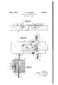
- FIG. 1 is a side elevation of the applied to the top surface of a railway cross tie, the holding clamps being omitted.
- Fig. 2 is a plan view, enlarged, of one end portion of the device, one of the holding clamps being shown.
- Fig. 3 is a transverse section on the line 33 of Fig. 2 the tie being turned upon its side to enable convenient boring of the transverse holes.
- the reference numeral 5 designates a railway cross tie in which a transverse hole 6 is to be bored.
- the jig itself consists of a longitudinally disposed bar 7 preferably formed of a flat strip, to which are secured end plates 8, at least one of which is adjustably secured to said bar by means to be described hereinafter.
- the plates 8 are adapted to rest upon the top or rail supporting surface of the tie, and each of said plates is provided with spaced depending ears 11 and 11 adapted to extend downwardly over the sides of the tie.
- the ears 11 and 11 are provided with holes 12 and 12 near their lower ends through which the bit or drill 13 passes in boring the hole 6, I
- said ears also carry bit guides 14 and 14', comprising semicylindrical members extending outwardly from the face of the respective ears and provided at their outer ends with semicircular guide flanges 15 and 15 aligned with the holes 12 and 12'. It should be noted that the guides 14 and 14' are respectively reversed in position, for a purpose to be described later.
- the plates 8 are provided with sight apertures in the form of slots 16, whose sides are preferably flared outwardly, as shown, to provide approximate knife edges at the lower surface of the plate. These slots 16 are adapted for visible alignment with the spike holes 17 previously bored in the tie. In as much as it is customary practice to bore the spike holes 17 before the tie is placed in position in the track, it is convenient and desirable to use said spike holes as means for locating the position of the jig upon the tie, and consequently locating the transverse holes 6.
- transverse flange 19 upon the bot-tom of each of the plates 8.
- This flange may be formed in any convenient manner, as for example by welding a rectangular bar to the bottom of said plates, and is positioned to rest in the tapered end of the notch 18 formed in the upper surface of the tie.
- the jig may be removably secured to the tie in any convenient manner, preferably by means of removable clamps of any Well known form, and as illustrated at 20.
- Handles 21 may be provided upon the plates 8 for convenience in lifting and moving the 1 Ihe plates 8 may be secured to the bar 7 in any suitable manner providing longitudinal adjustment of at least one of said plates.
- I have shown cap screws 22 extending through longitudinal slots 23 in the bar 7 and screwed into the plate 8, and a series of progressively aligned holes 2 ladapted to receive one or more tapered pins 25.
- the holes 24 are so positioned that only one or two of them will be aligned in any given relative position of the bar 7 and plate 8, so, thatsaid plate is adjusted by removing the pin or pins 25, loosening the screws 22, and shifting said plate upon the bar until the next pair of holes 24 are, aligned.
- one of the plates 8 may be permanently secured to the bar 7, by welding or otherwise.
- oneof said plates is adjusted with respect to the bar 7 in order to bring said slots and-spike holes into alignment.
- the turning over of the tie bringsthe guide 14 into the same position relative to the operator as was the guide l l in the first part of the operation. That is to say, the guide 1.4 is between the operators body. and the bit, as was the guide 14 in thefirst instance, and. in leaning over the outer endof the bit to apply thenecessary connecting said plate members in adjustable spaced relation, a pair of spaced arms eX- tending downwardly from each plate member embracing and lying adjacent to the sides of the tie, each pair of arms having aligned apertures therein, and substantially semicylindrica'l guides extending outwardly from. said arms, the uides upon one side of the tie being positioned above said apertures, and the guides upon the other side being positioned below said apertures.
- a jig for boring transverse holes in railway cross tiesh'aving previously bored spike holes therein comprising a pair of interconnected relatively adjustable plate members adapted to rest upon the upper surface of the tie, each of said members having means. determinative of definite position on the tie by registration with its spike holes, a pair of spaced arms extending downwardly from each plate member embracing and lyingadjacentto the sides of the tie, each pair of arms having aligned apertures therein, and substantially semicylindrical guides extending outwardly from said arms, the guides upon one side of the tie being positioned above said. apertures, and the guides upon the other side being positioned below said apertures.
Landscapes
- Engineering & Computer Science (AREA)
- Mechanical Engineering (AREA)
- Architecture (AREA)
- Civil Engineering (AREA)
- Structural Engineering (AREA)
- Machines For Laying And Maintaining Railways (AREA)
Description
May 3; 1932. w. H. KIRKBRIDE- BORING JIG FOR RAILWAY CROSSTIES- Filed Aug. 4, 1930 INVENTORT K/Veta 4 4 M Y mf ATTORNEYS Patented May 3, 1932 WALTER H. KIRKBRTDE, OF SAN FRANCISCO, CALIFORNIA BORING JIG FOE RAILWAY CROSSTIES Application filed August 4, 1930. Serial No. 472,898.
The present invention relates to jigs for locating and directing the boring ofholes in timbers, such for example as railway cross ties.
The invention is particularly adapted, and is 50 illustrated and described herein, for use in boring the transverse holes in cross ties for the purpose of securing thereto the curve rail plates for which United States Letters Patent No. 1,507 ,068 were issued to me September 2nd, 1924. These holes are bored horizontally through the tie from side to side. Their position and direction must be accurately located, because the said curve rail plate must lie flat upon the top of the tie, and because the distance apart of the two holes in each tie determines the gauge of the track.
The principal object of the present invention is to provide an inexpensive and easily operated for locating and directing the above described holes. It will be apparent,
however, that the device may be adapted for use in boring holes for other purposes, and it 7 is to be understood, moreover, that tl e form, construction and arrangement of the several parts of the device herein illustrated and described may be varied, within the limits of the claims hereto appended, without departing from the spirit of the invention.
A preferred embodiment of the invention is illustrated in the accompanying drawings in which Fig. 1 is a side elevation of the applied to the top surface of a railway cross tie, the holding clamps being omitted.
Fig. 2 is a plan view, enlarged, of one end portion of the device, one of the holding clamps being shown.
Fig. 3 is a transverse section on the line 33 of Fig. 2 the tie being turned upon its side to enable convenient boring of the transverse holes.
In the drawin s, the reference numeral 5 designates a railway cross tie in which a transverse hole 6 is to be bored. The jig itself consists of a longitudinally disposed bar 7 preferably formed of a flat strip, to which are secured end plates 8, at least one of which is adjustably secured to said bar by means to be described hereinafter.
The plates 8 are adapted to rest upon the top or rail supporting surface of the tie, and each of said plates is provided with spaced depending ears 11 and 11 adapted to extend downwardly over the sides of the tie. The ears 11 and 11 are provided with holes 12 and 12 near their lower ends through which the bit or drill 13 passes in boring the hole 6, I
and said ears also carry bit guides 14 and 14', comprising semicylindrical members extending outwardly from the face of the respective ears and provided at their outer ends with semicircular guide flanges 15 and 15 aligned with the holes 12 and 12'. It should be noted that the guides 14 and 14' are respectively reversed in position, for a purpose to be described later.
The plates 8 are provided with sight apertures in the form of slots 16, whose sides are preferably flared outwardly, as shown, to provide approximate knife edges at the lower surface of the plate. These slots 16 are adapted for visible alignment with the spike holes 17 previously bored in the tie. In as much as it is customary practice to bore the spike holes 17 before the tie is placed in position in the track, it is convenient and desirable to use said spike holes as means for locating the position of the jig upon the tie, and consequently locating the transverse holes 6.
If the upper surface of the tie is clapped or inclined as shown at 18 and described and illustrated in my copending application Serial Number 435,132 (since issued as Patent No. 1,780,396), for the purpose of laterally tilting the rail plate and the rail, it is preferable to provide a transverse flange 19 upon the bot-tom of each of the plates 8. This flange may be formed in any convenient manner, as for example by welding a rectangular bar to the bottom of said plates, and is positioned to rest in the tapered end of the notch 18 formed in the upper surface of the tie. The jig may be removably secured to the tie in any convenient manner, preferably by means of removable clamps of any Well known form, and as illustrated at 20.
its opposite side.
tie, oneof said plates is adjusted with respect to the bar 7 in order to bring said slots and-spike holes into alignment. The
is then securedtothe, tie by the clamps 20 and the tie is turned over upon its'side.
The operator,,standing behind the uppermost guide 14, Le. upon the right hand side of the tie, as shown in Fig. 8, inserts the bit or drill 13 through the hole 12 in the guide arm 11 and'bores part way through the tie, holding the bit in contact with the flange 15 of the guide member 14. In this position, the operator, bending over the bit to apply the necessary pressure; thereto, has
a clear View of said" bit as it enters and passes through the guide hole 12, his view being unobstructed by the guide member 14.
After boring part way through the tie in this position, the operator withdrawshis bit and'turns the tie half way over to rest upon This brings the arm 11 and the guide 14 uppermost, and the op eratorinserts his bit through the hole 12' and bores through the remaining portion of the'ti'e until said bit reaches the previously bored hole.
' Because the guides 14.- and 14 are respectivelyreversed in position, the turning over of the tie bringsthe guide 14 into the same position relative to the operator as was the guide l l in the first part of the operation. That is to say, the guide 1.4 is between the operators body. and the bit, as was the guide 14 in thefirst instance, and. in leaning over the outer endof the bit to apply thenecessary connecting said plate members in adjustable spaced relation, a pair of spaced arms eX- tending downwardly from each plate member embracing and lying adjacent to the sides of the tie, each pair of arms having aligned apertures therein, and substantially semicylindrica'l guides extending outwardly from. said arms, the uides upon one side of the tie being positioned above said apertures, and the guides upon the other side being positioned below said apertures.
2. A jig for boring transverse holes in railway cross tiesh'aving previously bored spike holes therein, comprising a pair of interconnected relatively adjustable plate members adapted to rest upon the upper surface of the tie, each of said members having means. determinative of definite position on the tie by registration with its spike holes, a pair of spaced arms extending downwardly from each plate member embracing and lyingadjacentto the sides of the tie, each pair of arms having aligned apertures therein, and substantially semicylindrical guides extending outwardly from said arms, the guides upon one side of the tie being positioned above said. apertures, and the guides upon the other side being positioned below said apertures. In testimony whereof I have signed my nameto this specification.
WALTER H. KIRKBRIDE.
Priority Applications (1)
| Application Number | Priority Date | Filing Date | Title |
|---|---|---|---|
| US472893A US1856485A (en) | 1930-08-04 | 1930-08-04 | Boring jig for railway crossties |
Applications Claiming Priority (1)
| Application Number | Priority Date | Filing Date | Title |
|---|---|---|---|
| US472893A US1856485A (en) | 1930-08-04 | 1930-08-04 | Boring jig for railway crossties |
Publications (1)
| Publication Number | Publication Date |
|---|---|
| US1856485A true US1856485A (en) | 1932-05-03 |
Family
ID=23877330
Family Applications (1)
| Application Number | Title | Priority Date | Filing Date |
|---|---|---|---|
| US472893A Expired - Lifetime US1856485A (en) | 1930-08-04 | 1930-08-04 | Boring jig for railway crossties |
Country Status (1)
| Country | Link |
|---|---|
| US (1) | US1856485A (en) |
Cited By (2)
| Publication number | Priority date | Publication date | Assignee | Title |
|---|---|---|---|---|
| US2886989A (en) * | 1954-01-14 | 1959-05-19 | Independent Lock Co | Boring jig construction |
| US4793747A (en) * | 1988-04-18 | 1988-12-27 | Reitz George J | Stair rail spindle jig |
-
1930
- 1930-08-04 US US472893A patent/US1856485A/en not_active Expired - Lifetime
Cited By (2)
| Publication number | Priority date | Publication date | Assignee | Title |
|---|---|---|---|---|
| US2886989A (en) * | 1954-01-14 | 1959-05-19 | Independent Lock Co | Boring jig construction |
| US4793747A (en) * | 1988-04-18 | 1988-12-27 | Reitz George J | Stair rail spindle jig |
Similar Documents
| Publication | Publication Date | Title |
|---|---|---|
| US1583611A (en) | Detachable extension clamp | |
| US1856485A (en) | Boring jig for railway crossties | |
| ES8100389A1 (en) | Track working machine with a ballast plow arrangement | |
| US1638848A (en) | Clamp | |
| US3031669A (en) | Apparatus for aligning, spacing and holding connectors | |
| US1510219A (en) | Auger guide | |
| US1297521A (en) | Train-flagging device. | |
| US534661A (en) | Woodworking-machine | |
| US2142472A (en) | Track lining gauge | |
| US1590145A (en) | Tie-setting tool | |
| US2235994A (en) | Scotch block | |
| US1438404A (en) | Spot board for railroad surveying | |
| DE463820C (en) | Drilling jig | |
| US415198A (en) | Ratchet-drill frame | |
| US1669595A (en) | Rail-aligning tool | |
| US1677063A (en) | Gauge tool | |
| US1524169A (en) | Adjustable rail-breaking clamp | |
| US1767935A (en) | Watch-crystal-fitting device | |
| US1497987A (en) | Metallic tie | |
| US1568745A (en) | Printer s clamp | |
| US1790039A (en) | Tie tamper | |
| DE471869C (en) | Teaching for coring the drill holes for railway sleeper screws when using core bolts under the action of a spring | |
| US1540622A (en) | Measuring and squaring device for sash and door clamping machines | |
| US1615703A (en) | Saw guide | |
| US1598298A (en) | Rail puller |