US1856483A - Press for the extrusion of metals - Google Patents
Press for the extrusion of metals Download PDFInfo
- Publication number
- US1856483A US1856483A US558528A US55852831A US1856483A US 1856483 A US1856483 A US 1856483A US 558528 A US558528 A US 558528A US 55852831 A US55852831 A US 55852831A US 1856483 A US1856483 A US 1856483A
- Authority
- US
- United States
- Prior art keywords
- metal
- press
- die
- point
- extrusion
- Prior art date
- Legal status (The legal status is an assumption and is not a legal conclusion. Google has not performed a legal analysis and makes no representation as to the accuracy of the status listed.)
- Expired - Lifetime
Links
Images

Classifications
-
- B—PERFORMING OPERATIONS; TRANSPORTING
- B21—MECHANICAL METAL-WORKING WITHOUT ESSENTIALLY REMOVING MATERIAL; PUNCHING METAL
- B21C—MANUFACTURE OF METAL SHEETS, WIRE, RODS, TUBES, PROFILES OR LIKE SEMI-MANUFACTURED PRODUCTS OTHERWISE THAN BY ROLLING; AUXILIARY OPERATIONS USED IN CONNECTION WITH METAL-WORKING WITHOUT ESSENTIALLY REMOVING MATERIAL
- B21C25/00—Profiling tools for metal extruding
- B21C25/06—Press heads, dies, or mandrels for coating work
Definitions
- This invention relates to presses used for the extrusion of tubular lengths of lead or similar metal forming, for instance, the sheath of an electric cable.
- the metal is extruded through the annular space between two circular dies (the outer die will be for convenience of reference spoken of as the die hereinafter and the inner hollow tapered die as the point-).
- the space between the point and die is left full of metal.
- the die can be readily removed since it is accessiblefrom the outside of the
- the metal remaining between the die and the point may form an obstacle to the removal of the latter and will always prevent its replacement by a point of'large size. Accordinglyit is necessary to provide for a portion of the metal to be taken away. Hitherto this has been done either by melting the metal or by shearing oil the piece lying in' front of the point'by forcing the latter forward after opening out a sufliciently large aperture in the end of the press and inserting there a ring to serve as the outer member of the sheathing press.
- the present invention we provide an improved arrangement for facilitating the removal and replacement of the. point.
- this arrangement after removing the die and the part or parts which immediately sup port it we insert in their place a tubular cutter or trepanning tool and rotate it while feeding it inward until it has cut through thegreater part of the metal to beremoved leaving only a thin layer directly adjacent to the point.
- the point can'then readily be pushed or drawn forward out of the press carrying with it the ring of metal. As this ring can be cut out at a larger diameter than the maximum diameter of the point the new point may easily be inserted into position through the aperture in the metal.
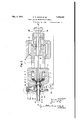
- Figure 1 shows diagrammatically in section a'metal extrusion press as used for applying a lead-sheath to an electric cable, and illustrates the condition of the press at the end of the extruding operation, previous to the changing of the point and die.
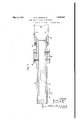
- Figure 2 is a similar view with the die removed illustrating the cutting or trepanning operation.
- Figure3 is a detailed sectional view of the trepanning tool on a larger scale.
- the lead is contained in a semi-molten or plastic state within an annular chamber 1 formed within a, lead receiver 2 and surrounding a point holder 3 being introduced into this chamber in a molten condition through a suitable charging orifice 4.
- the discharge of the lead is effected by the movement of a piston 5 from its original position as indicated in Figure 2 to its extreme position indicated in Figure 1.
- This movement or pressure stroke is obtained by means of a hydraulic ram 6 having an extension 7 to which the piston 5 is attached, the ram being operated by hydraulic pressure within a cylinder 8.
- the metal tube or sheath is formed by extrusion of the plastic metal between a die 9 and a point 10, its diameter and wall-thickness being controlled by the size and relative positions of these two components.
- a main block 11 which accommodates a die-holder 12 sliding therein and carrying the die 9; a sleeve 13 screwed into the main block 11 serves to support the die-holder in position against the pressure of the extruded metal.
- Axial openings 14 and 15 in the ram 6 and the point holder 8. provide a path for the passage of the cable from the back of the press to the point of application of the metal V the cylindrical passage through the centre of the holder; the die 9 is removed with the holder. Removal of the point 10 is hindered by the presence of a cylindrical mass of solidified metal 17
- Figure 2 shows the process of cutting a readily. removable cylinder of metal from the front of the point 10 by ,means of a cutting or trepanning tool 18, the details of which are shown in Figure 3.
- the cutting tool 18 consists of a hollow cylindrical portion 29 carrying at one end a cutting head 19 attached thereto by means of a screw thread and locking pegs 30;
- a cylindrical threaded bush 31 which is made a driving fit on the cylindrical portion 29 and is prevented from rotatingthereon by means of sunken screws '32, is of such dimensions that it may be screwed into the internally threaded aper-v ture within .the main block 11.
- the cutter 7 head 19 is formed with cutting teeth the cutting edges of which are indicated at 33 in Figure 3. Rotation of the tool is effected by means of a driven. worm wheel 20 which engages with the cylindrical portion 29 by means of a feather or key 23 sliding in a keyway 24.
- the worm wheel 20 engages'with a worm gear 21 housed in a bracket 34: detachab'ly mounted upon a projection or seating 35 which is formed upon the front of the lead receiver 2.
- the worm gear is driven from an electric motor 22 by means of a suitable gearing such as a chain drive 36 as indicated in Figure 2.
- a detachablecap 37 formed to fit over the main block 11 incorporates a bearing 38 which accommodates the hub 39 of the worm wheel 20 thereby serving to supp'ortthe wheel during the cutting process.
- the cutting edges 33 tending to remove a cylindrical block of metal from the front of the point 10.
- the bar inserted from the back of the press, has at its outer end a T-piece 27 which engages with two studs 28 attached to the end of the hydraulic ram 6, the latter having been returned to its original position as represented by Figure 2 before the cutting operation,v
- a short stroke of the ram serves to drive forward the point, breaking through the thin remaining wall of metal, whereupon the point may be carried forward to the front of the press and removed by any convenient means.
- a v 1 V V c The cutting or trepanning tool is designed to remove a block of metal of such a diameter that free passage is permitted for the maximum size of point which may be used with the press.
- an arrangement for the removal of the-inner die comprising means for supporting, driving and feeding forward a tubular cutterin the annular space made available by the removal ofthe outer die in combination with means for pushing forward the inner die to'break the thin ring of metal left by the cutter.
- an arrangement for the removal of outer die for cutting a circular groove in the metal in front of the inner die in combination with an ejector rod having a front end adapted to engage the rear part of the inner die and means for coupling the rear end of said rod with the ram of the press.
Landscapes
- Engineering & Computer Science (AREA)
- Mechanical Engineering (AREA)
- Extrusion Of Metal (AREA)
Description
May 3, 1932-. E. E JUDGE ET AL 1,356,483
PRESS FOR THE EXTRUSION OF METALS N 8 L l I l/V VE N TOR3 HTTORIVfXS' E. E. JUDGE ET AL PRESS IQE THE EXTRUSION OF METALS May 3, 1932.
Filed Aug. 21, 1951 Fig. 2.
5 Sheets-Sheet 2 *4 g a a #vvnvrons n N a Q We. M 4
Fig. 3.
E E. JUDGE ET AL PRESS 'FOR THE EXTRUSION OF METALS Filed Aug. 21, 1931 ca cq .3 Sheets-Sheet 5 press.
Patented May 3, 1932 UNirED STATES PATENT GFFICE ERNEST EDWARD JUDGE AND FRANCIS HENRY FRY, 0F GRAVES END, KENT, ENGLAND, ASSIGNOR-S T0 W. T. HENLEYS TELEGRAPH WORKS COMPANY LIMITED, OF LONDON,
ENGLAND, A BRITISH COMPANY PRESS FOR THE EXTR'USION OF METALS 7 Application filed August 21, 1931, Serial No. 558,528, and in Great Britain September 24, 1930.
This invention relates to presses used for the extrusion of tubular lengths of lead or similar metal forming, for instance, the sheath of an electric cable. In the type of press to which the invention applies the metal is extruded through the annular space between two circular dies (the outer die will be for convenience of reference spoken of as the die hereinafter and the inner hollow tapered die as the point-). At the end of a pressing operation the space between the point and die is left full of metal. When a change in the size of tube to be extruded is required to beeffected it is necessary to take out the point and die and replace them by other similar-members appropriate for the new size. The die can be readily removed since it is accessiblefrom the outside of the The metal remaining between the die and the point may form an obstacle to the removal of the latter and will always prevent its replacement by a point of'large size. Accordinglyit is necessary to provide for a portion of the metal to be taken away. Hitherto this has been done either by melting the metal or by shearing oil the piece lying in' front of the point'by forcing the latter forward after opening out a sufliciently large aperture in the end of the press and inserting there a ring to serve as the outer member of the sheathing press.
By the present invention we provide an improved arrangement for facilitating the removal and replacement of the. point. In this arrangement after removing the die and the part or parts which immediately sup port it we insert in their place a tubular cutter or trepanning tool and rotate it while feeding it inward until it has cut through thegreater part of the metal to beremoved leaving only a thin layer directly adjacent to the point. We then remove the cutter and apply to the rearof the point suflicient pressure to force it forward through a short distance thereby breaking through the thin ring of metal which has not been cut. The point can'then readily be pushed or drawn forward out of the press carrying with it the ring of metal. As this ring can be cut out at a larger diameter than the maximum diameter of the point the new point may easily be inserted into position through the aperture in the metal.
An example of the application to a metal extrusion press of the invention as set forth above is hereafter described with reference to the accompanying diagrammatic drawings.
Figure 1 shows diagrammatically in section a'metal extrusion press as used for applying a lead-sheath to an electric cable, and illustrates the condition of the press at the end of the extruding operation, previous to the changing of the point and die.
Figure 2 is a similar view with the die removed illustrating the cutting or trepanning operation.
Figure3 is a detailed sectional view of the trepanning tool on a larger scale.
Previous to the extruding operation the lead is contained in a semi-molten or plastic state within an annular chamber 1 formed within a, lead receiver 2 and surrounding a point holder 3 being introduced into this chamber in a molten condition through a suitable charging orifice 4. The discharge of the lead is effected by the movement of a piston 5 from its original position as indicated in Figure 2 to its extreme position indicated in Figure 1. This movement or pressure stroke is obtained by means of a hydraulic ram 6 having an extension 7 to which the piston 5 is attached, the ram being operated by hydraulic pressure within a cylinder 8.
The metal tube or sheath is formed by extrusion of the plastic metal between a die 9 and a point 10, its diameter and wall-thickness being controlled by the size and relative positions of these two components. Within the lead receiver 2 is held, by means of a strong screw-thread, a main block 11 which accommodates a die-holder 12 sliding therein and carrying the die 9; a sleeve 13 screwed into the main block 11 serves to support the die-holder in position against the pressure of the extruded metal.
2. In an'extrusion press in which tubular lengths of metal are extruded through an annular space between an outer die and an inner die, an arrangement for the removal of the-inner die, said arrangementcomprising means for supporting, driving and feeding forward a tubular cutterin the annular space made available by the removal ofthe outer die in combination with means for pushing forward the inner die to'break the thin ring of metal left by the cutter.
'3. In an extrusion press in which tubular lengths of metal are extruded through an annular space betweenan outer die and an inner die, an arrangement for the removal of outer die for cutting a circular groove in the metal in front of the inner die, in combination with an ejector rod having a front end adapted to engage the rear part of the inner die and means for coupling the rear end of said rod with the ram of the press.
In testimony whereof We aflix our signatures.
ERNEST EDWARD JUDGE. FRANCIS HENRY FRY.
Applications Claiming Priority (1)
| Application Number | Priority Date | Filing Date | Title |
|---|---|---|---|
| GB1856483X | 1930-09-24 |
Publications (1)
| Publication Number | Publication Date |
|---|---|
| US1856483A true US1856483A (en) | 1932-05-03 |
Family
ID=10892109
Family Applications (1)
| Application Number | Title | Priority Date | Filing Date |
|---|---|---|---|
| US558528A Expired - Lifetime US1856483A (en) | 1930-09-24 | 1931-08-21 | Press for the extrusion of metals |
Country Status (1)
| Country | Link |
|---|---|
| US (1) | US1856483A (en) |
Cited By (1)
| Publication number | Priority date | Publication date | Assignee | Title |
|---|---|---|---|---|
| US3394579A (en) * | 1965-10-21 | 1968-07-30 | Hall Carlos | Methods and apparatus for the production of extruded bodies |
-
1931
- 1931-08-21 US US558528A patent/US1856483A/en not_active Expired - Lifetime
Cited By (1)
| Publication number | Priority date | Publication date | Assignee | Title |
|---|---|---|---|---|
| US3394579A (en) * | 1965-10-21 | 1968-07-30 | Hall Carlos | Methods and apparatus for the production of extruded bodies |
Similar Documents
| Publication | Publication Date | Title |
|---|---|---|
| US3563079A (en) | Indirect extrusion with skull skimming | |
| GB1174027A (en) | Extrusion Apparatus | |
| US2063563A (en) | Manufacture of extruded metal shapes by hot hydraulic extrusion | |
| US1856483A (en) | Press for the extrusion of metals | |
| US3826122A (en) | Mandrel for extruding tubing | |
| US3369384A (en) | Metal extrusion | |
| US2031008A (en) | Apparatus for extruding metal | |
| US1847365A (en) | Extrusion of metal | |
| US3723017A (en) | Drilling chuck | |
| US3296848A (en) | Method and apparatus for extruding tubular members from solid billets or the like | |
| US3243984A (en) | Extrusion press for hollow extrusions | |
| US411060A (en) | robertson | |
| US6164811A (en) | Extruder assembly with improved screw removal capability | |
| US3369385A (en) | Metal extrusion apparatus | |
| EP0043025B1 (en) | Indirect metal extrusion press and apparatus for removing "frozen" billets | |
| DE583845C (en) | Process for removing the mandrel from pipe extrusions, in particular lead cable presses | |
| US3810379A (en) | Apparatus for the extrusion of billets | |
| US3404552A (en) | Billet piercing and extrusion | |
| US2170556A (en) | Process and apparatus for making rivets | |
| GB363421A (en) | Improvements in presses for the extrusion of metals | |
| US2425270A (en) | Method and apparatus for forming blanks for post and pedestal insulators | |
| GB1165010A (en) | Improvements in or relating to the Extrusion of Helically Fluted Cutting Tools. | |
| US939735A (en) | Thread-cutting tool. | |
| CN113894169B (en) | Method for processing small-modulus long and thin external spline on thin-walled tube | |
| JP6620550B2 (en) | Double-action extrusion press mandrel rotation prevention device |