US1856462A - Sign - Google Patents
Sign Download PDFInfo
- Publication number
- US1856462A US1856462A US353118A US35311829A US1856462A US 1856462 A US1856462 A US 1856462A US 353118 A US353118 A US 353118A US 35311829 A US35311829 A US 35311829A US 1856462 A US1856462 A US 1856462A
- Authority
- US
- United States
- Prior art keywords
- sign
- ribs
- signs
- glass
- face
- Prior art date
- Legal status (The legal status is an assumption and is not a legal conclusion. Google has not performed a legal analysis and makes no representation as to the accuracy of the status listed.)
- Expired - Lifetime
Links
- 239000011521 glass Substances 0.000 description 15
- 230000005540 biological transmission Effects 0.000 description 1
- 238000010276 construction Methods 0.000 description 1
- 238000005286 illumination Methods 0.000 description 1
- 239000002184 metal Substances 0.000 description 1
- 238000012856 packing Methods 0.000 description 1
Images
Classifications
-
- G—PHYSICS
- G09—EDUCATION; CRYPTOGRAPHY; DISPLAY; ADVERTISING; SEALS
- G09F—DISPLAYING; ADVERTISING; SIGNS; LABELS OR NAME-PLATES; SEALS
- G09F13/00—Illuminated signs; Luminous advertising
- G09F13/04—Signs, boards or panels, illuminated from behind the insignia
- G09F13/14—Arrangements of reflectors therein
Definitions
- This invention relates to daylight signs and to prismatic glass for use therein.
- the principal object of the invention is to provide a sign capable of being viewed effectively from lateral or slightly lateral positions.
- a sign illuminated by daylight through a reflexive or refractive medium is hung at right angles to the face of a building (particularly near the street level of a high building) an observer only views such a sign effectively when he is at the same distance (or less) from the face of the building as the sign itself.
- the distance a sign is allowed to overhang a pavement is relatively small only a proportion of passers-by on a wide pavement view it effectively.
- a sign made according to the present invention and adapted to be hung out from the face of a building comprises a panel or stencil (hereinafter referred to as a stencil) and a ribbed prismatic refractive glass or a reflector whereof the ribs are inclined to the horizontal, the higher ends of the ribs being next the building.
- the normal to the reflecting or refracting surface is directed laterally upwards and away from the building, and light derived from a lateral or vertical region of the sky is directed laterally of the sign after deviation to: render it visible to persons who are also laterally situated at the same side of the ll prefer to make the angle of tilt of the surfaces as large as possible to extend the field of view, the limit being usually fixed by the hei ht of buildings or other masks on the opposite side of a street.
- the inclination of the ribs may 7 approach the vertical.
- Such signs having prismatic glass arranged to give what I may term lateral deviation may be used in single-fronted signs, in parallel double-fronted signs, or in V-shaped double-fronted signs.
- Considerable economy of space may be sometimes effected by arranging the prismatic glass with its ribs away from the stencil and towards the incident light.
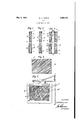
- Fig. l is a vertical sectional end view of a simple single-sided sign.
- Fig. 2- is a similar view of an alternative form.
- Fig. 3 represents a back view of the sheet ribs which have a long and a short face.
- the comparatively long reflecting faces 3a, 8a are silvered and the short faces 8b, 8?) may be free of silvering.
- Fig. 2 shows the frame 1,'stencil 2 and backing glass 3, but in this case the main lighting comes from behind, i. e. the right of the figure, and is transmitted through the glass; and the ribs may be regular and are acute-angled for satisfactory refraction and transmission of the light through the stencil.
- the ribs 30 are shown veryconsiderably inclined at Fig. 3, as for a position where the best light is derived from considerably to one side of the sign.
- Figs. 4 and 5 show a double-sided form generally similar to the form shown at Fig. 1.
- the frame 1 holds a stencil 2 and backing gales 3 at each side. Daylight from the top and outer sides is reflected by the inclined silvered strips 3a, 3a shown shaded in Fig.
- the casing also contains suitable sources of artificial light 4;, l at the top and side edges, subtended by the ribs, so as to illuminate the stencils in an alternative manner at night by throwing the light through the unsilvered steps or short faces 3?), 3b.
- suitable sources of artificial light 4 l at the top and side edges, subtended by the ribs, so as to illuminate the stencils in an alternative manner at night by throwing the light through the unsilvered steps or short faces 3?), 3b.
- packing strips 5 are shown between the is arranged with the ribs running 2 prismatic side of the glass and the casing.
- the likeconstitutingthe base lr may be ableto illuminate both stencils simultaneously by'a row of lamps placed along the baseof the triangleand generally somewhat belowv the level of. the stencils.
- a daylight sign a frame, a stencil, a light-deviating glass panel positioned behind and serving to illuminate said stencil, said panel having a series of parallel ribs inclined to the horizontal, and means to attach saicLframe toa vertical supporting, surf sothat saidfribs Lslopeaupwardly; toward said surface.
- a daylight sign having means to [define display. matter, means .toilluminat-e the sign; comprising a. lightsdeviating panel of rectangular out-line positioned behind said display matter, said panel including lightdeviating, parallel, ribs extendingobliquely across saith-rectangular paneli .WILI-JIAMLALBERI? URN-s;
- ardaylightsign a frame, a stencil, a lightreflecting glass panel positionedbehind and. adapted; to illuminate saidstencil and r I I rhazving parallel ribs; inclined to the horizon:
Landscapes
- Physics & Mathematics (AREA)
- General Physics & Mathematics (AREA)
- Engineering & Computer Science (AREA)
- Theoretical Computer Science (AREA)
- Illuminated Signs And Luminous Advertising (AREA)
Description
y 3, 1932. w. A. BURNS 1,856,462
SIGN
Filed April 6, 1929 Patented May 3, 1932 UNITED-STATES PATENT OFFICE WILLIAM ALBERT BURNS, OF BRONDESBURY, LONDON, ENGLAND, ASSIGNOR TO SOLA- FLEX SIGNS AMALGAMATED LIMITED, 01? LONDON, ENGLAND SIGN Application filed April 6, 1928, Serial No. 353,118, and in Great Britain April 17, 1928.
This invention relates to daylight signs and to prismatic glass for use therein.
The principal object of the invention is to provide a sign capable of being viewed effectively from lateral or slightly lateral positions. In the ordinary way, if a sign illuminated by daylight through a reflexive or refractive medium is hung at right angles to the face of a building (particularly near the street level of a high building) an observer only views such a sign effectively when he is at the same distance (or less) from the face of the building as the sign itself. As the distance a sign is allowed to overhang a pavement is relatively small only a proportion of passers-by on a wide pavement view it effectively.
Accordingly, a sign made according to the present invention and adapted to be hung out from the face of a building comprises a panel or stencil (hereinafter referred to as a stencil) and a ribbed prismatic refractive glass or a reflector whereof the ribs are inclined to the horizontal, the higher ends of the ribs being next the building. lVith this arrangement, the normal to the reflecting or refracting surface is directed laterally upwards and away from the building, and light derived from a lateral or vertical region of the sky is directed laterally of the sign after deviation to: render it visible to persons who are also laterally situated at the same side of the ll prefer to make the angle of tilt of the surfaces as large as possible to extend the field of view, the limit being usually fixed by the hei ht of buildings or other masks on the opposite side of a street. In an extreme case where the building carrying the sign is openly exposed, the inclination of the ribs may 7 approach the vertical.
Such signs having prismatic glass arranged to give what I may term lateral deviation, may be used in single-fronted signs, in parallel double-fronted signs, or in V-shaped double-fronted signs. In the case of double fronted signs care must be taken that neither construction masks the incident rays to the other. Considerable economy of space may be sometimes effected by arranging the prismatic glass with its ribs away from the stencil and towards the incident light.
' Several preferred forms are shown upon the accompanying drawings wherein Fig. l is a vertical sectional end view of a simple single-sided sign.
Fig. 2-is a similar view of an alternative form.
Fig. 3 represents a back view of the sheet ribs which have a long and a short face. The
Fig. 2 shows the frame 1,'stencil 2 and backing glass 3, but in this case the main lighting comes from behind, i. e. the right of the figure, and is transmitted through the glass; and the ribs may be regular and are acute-angled for satisfactory refraction and transmission of the light through the stencil. The ribs 30 are shown veryconsiderably inclined at Fig. 3, as for a position where the best light is derived from considerably to one side of the sign.
Figs. 4 and 5 show a double-sided form generally similar to the form shown at Fig. 1. The frame 1 holds a stencil 2 and backing gales 3 at each side. Daylight from the top and outer sides is reflected by the inclined silvered strips 3a, 3a shown shaded in Fig.
5. The casing also contains suitable sources of artificial light 4;, l at the top and side edges, subtended by the ribs, so as to illuminate the stencils in an alternative manner at night by throwing the light through the unsilvered steps or short faces 3?), 3b. In each case packing strips 5 are shown between the is arranged with the ribs running 2 prismatic side of the glass and the casing.
While I have described this invention in connection with outdoor signs, itcan be conveniently applied to indoor signs, or signs under cover provided awindow, fan'light,
glass r.o.of, orr other suchvaperturergiving a View ofithesky, isaavailable; as}by choice of site and selection of a suitable prismatic glass and inclination of the same with respect to= the: horizontal, J signs:v may: be efliciently exhibited. in; positions:v where they would be useless if the system of horizontal ribbing was employed. lVhere suchwsignsare required to be illnm'inated' by artificial light, I may employ knowmmethodsin thecase of. single, signs, or double signs :havingpara'llel panel. With Veshap ed, signs, where the arrangement in planisthatrof a triangle-the two outside ends oftthe:stencilsnieetingat'the apex and;the
' face of'a building or. the likeconstitutingthe base lrmay be ableto illuminate both stencils simultaneously by'a row of lamps placed along the baseof the triangleand generally somewhat belowv the level of. the stencils.
lt'gwillbegunderstoodthat although l, have illustrated reflectors of glassv yet metal re fiectorsmay be usedwhere found convenient,
the:sam'e;being provided with inclined ribs as, and; for; the purpose describedl I. claim':--
5. In a daylight sign, a frame, a stencil, a light-deviating glass panel positioned behind and serving to illuminate said stencil, said panel having a series of parallel ribs inclined to the horizontal, and means to attach saicLframe toa vertical supporting, surf sothat saidfribs Lslopeaupwardly; toward said surface.
6. For use in a daylight sign having means to [define display. matter, means .toilluminat-e the sign; comprising a. lightsdeviating panel of rectangular out-line positioned behind said display matter, said panel including lightdeviating, parallel, ribs extendingobliquely across saith-rectangular paneli .WILI-JIAMLALBERI? URN-s;
horizontal, said-t ribs-having a; short. face and sunfa-cesa said member being; positioned behind the display matter.
3., Inadaylight sign,i means to define dis:
play, matter, and means to illuminate the signcomprising alight-reflecting glass panel a.v long, face, s-a-idlong faces having reflecting havi'ngparallel ribs inclined to, the horizon- 1 t al, said ribs having; ashort, face and. along face, the long faces of said: ribsbeing; silvered said glass panel being positioned bethe; display matter.v
4. In; ardaylightsign, a frame, a stencil, a lightreflecting glass panel positionedbehind and. adapted; to illuminate saidstencil and r I I rhazving parallel ribs; inclined to the horizon:
ta-1,, said, ribs-having a. short 7 face'and a. long face, thelong faces.- of. said ribs beingf sil1- vered, and a source; of artificial illumination to illuminate said stencil alternately through said shortfacesn- 1 V
Applications Claiming Priority (1)
| Application Number | Priority Date | Filing Date | Title |
|---|---|---|---|
| GB1856462X | 1928-04-17 |
Publications (1)
| Publication Number | Publication Date |
|---|---|
| US1856462A true US1856462A (en) | 1932-05-03 |
Family
ID=10892108
Family Applications (1)
| Application Number | Title | Priority Date | Filing Date |
|---|---|---|---|
| US353118A Expired - Lifetime US1856462A (en) | 1928-04-17 | 1929-04-06 | Sign |
Country Status (1)
| Country | Link |
|---|---|
| US (1) | US1856462A (en) |
Cited By (4)
| Publication number | Priority date | Publication date | Assignee | Title |
|---|---|---|---|---|
| US3973342A (en) * | 1971-04-19 | 1976-08-10 | Gubela Hans Erich | Light reflector plate and method of fabrication |
| US20140208624A1 (en) * | 2013-01-31 | 2014-07-31 | 3M Innovative Properties Company | Self illuminated signage for printed graphics |
| US20150121732A1 (en) * | 2013-11-05 | 2015-05-07 | 3M Innovative Properties Company | Hybrid self illuminated and actively back lit signage for printed graphics |
| US20160358521A1 (en) * | 2015-06-05 | 2016-12-08 | 3M Innovative Properties Company | Self illuminated signage for printed graphics with oriented turning layer |
-
1929
- 1929-04-06 US US353118A patent/US1856462A/en not_active Expired - Lifetime
Cited By (9)
| Publication number | Priority date | Publication date | Assignee | Title |
|---|---|---|---|---|
| US3973342A (en) * | 1971-04-19 | 1976-08-10 | Gubela Hans Erich | Light reflector plate and method of fabrication |
| US20140208624A1 (en) * | 2013-01-31 | 2014-07-31 | 3M Innovative Properties Company | Self illuminated signage for printed graphics |
| US8915002B2 (en) * | 2013-01-31 | 2014-12-23 | 3M Innovative Properties Company | Self illuminated signage for printed graphics |
| US20150068080A1 (en) * | 2013-01-31 | 2015-03-12 | 3M Innovative Properties Company | Self illuminated signage for printed graphics |
| US9171489B2 (en) * | 2013-01-31 | 2015-10-27 | 3M Innovative Properties Company | Self illuminated signage for printed graphics |
| US20150121732A1 (en) * | 2013-11-05 | 2015-05-07 | 3M Innovative Properties Company | Hybrid self illuminated and actively back lit signage for printed graphics |
| US9070312B2 (en) * | 2013-11-05 | 2015-06-30 | 3M Innovative Properties Company | Hybrid self illuminated and actively back lit signage for printed graphics |
| US9208704B2 (en) * | 2013-11-05 | 2015-12-08 | 3M Innovative Properties Company | Hybrid self illuminated and actively back lit signage for printed graphics |
| US20160358521A1 (en) * | 2015-06-05 | 2016-12-08 | 3M Innovative Properties Company | Self illuminated signage for printed graphics with oriented turning layer |
Similar Documents
| Publication | Publication Date | Title |
|---|---|---|
| US2428827A (en) | Manner and means for illuminating room space | |
| US4425603A (en) | Indirect light-distributing ceiling fixtures with alternate reflector array | |
| US4136474A (en) | Illuminated overhead advertising display | |
| US1652347A (en) | Lighting apparatus | |
| US4453201A (en) | Electrically illuminated cross | |
| JP2005521993A (en) | Uniform illumination double-sided lighting panel | |
| US1856462A (en) | Sign | |
| US2052755A (en) | Wall construction | |
| US20040128890A1 (en) | Back illuminated ceiling mounted display panel | |
| US3419986A (en) | Sign construction with translucent reflector | |
| US2074671A (en) | Interiorly illuminated sign | |
| US2153595A (en) | Illuminable fixture | |
| US982823A (en) | Means for illuminating interiors of buildings. | |
| US3076277A (en) | Illuminated sign | |
| GB296885A (en) | Improvements in and relating to illuminating apparatus | |
| US2077759A (en) | Sign | |
| CN211718685U (en) | Transparent rear projection screen and projection system | |
| US1780373A (en) | Illuminating device | |
| EP0591221A1 (en) | Artificial window apparatus | |
| USRE18166E (en) | Luminous display | |
| US20210056875A1 (en) | Solar panel lighting for house number device | |
| US303496A (en) | Method of displaying signs | |
| US1769824A (en) | Sign | |
| US1809761A (en) | Luminous display or reflector sign | |
| GB392284A (en) | Improvements in or relating to illuminating devices for use with mirrors |