JP2005521993A - Uniform illumination double-sided lighting panel - Google Patents
Uniform illumination double-sided lighting panel Download PDFInfo
- Publication number
- JP2005521993A JP2005521993A JP2003580906A JP2003580906A JP2005521993A JP 2005521993 A JP2005521993 A JP 2005521993A JP 2003580906 A JP2003580906 A JP 2003580906A JP 2003580906 A JP2003580906 A JP 2003580906A JP 2005521993 A JP2005521993 A JP 2005521993A
- Authority
- JP
- Japan
- Prior art keywords
- lighting panel
- panel according
- partition
- chamber
- lighting
- Prior art date
- Legal status (The legal status is an assumption and is not a legal conclusion. Google has not performed a legal analysis and makes no representation as to the accuracy of the status listed.)
- Pending
Links
- 238000005286 illumination Methods 0.000 title claims description 16
- 238000005192 partition Methods 0.000 claims abstract description 36
- 239000011022 opal Substances 0.000 claims description 4
- 229920001971 elastomer Polymers 0.000 claims description 2
- 239000000806 elastomer Substances 0.000 claims description 2
- 239000000463 material Substances 0.000 description 7
- 230000004048 modification Effects 0.000 description 5
- 238000012986 modification Methods 0.000 description 5
- 241001631457 Cannula Species 0.000 description 4
- 239000004033 plastic Substances 0.000 description 4
- 229920003023 plastic Polymers 0.000 description 4
- 238000012423 maintenance Methods 0.000 description 3
- 238000005034 decoration Methods 0.000 description 2
- 238000009792 diffusion process Methods 0.000 description 2
- 230000000694 effects Effects 0.000 description 2
- 239000004744 fabric Substances 0.000 description 2
- 238000000926 separation method Methods 0.000 description 2
- 229920000742 Cotton Polymers 0.000 description 1
- 230000005856 abnormality Effects 0.000 description 1
- 239000000853 adhesive Substances 0.000 description 1
- 230000001070 adhesive effect Effects 0.000 description 1
- 230000002860 competitive effect Effects 0.000 description 1
- 238000010276 construction Methods 0.000 description 1
- 230000007547 defect Effects 0.000 description 1
- 238000009826 distribution Methods 0.000 description 1
- 239000000428 dust Substances 0.000 description 1
- 239000013013 elastic material Substances 0.000 description 1
- 230000007613 environmental effect Effects 0.000 description 1
- 238000007689 inspection Methods 0.000 description 1
- 239000005392 opalescent glass Substances 0.000 description 1
- 230000003287 optical effect Effects 0.000 description 1
- 230000000737 periodic effect Effects 0.000 description 1
- 239000002985 plastic film Substances 0.000 description 1
- 239000004417 polycarbonate Substances 0.000 description 1
- 229920000515 polycarbonate Polymers 0.000 description 1
- 230000005855 radiation Effects 0.000 description 1
- 230000001502 supplementing effect Effects 0.000 description 1
- 239000012780 transparent material Substances 0.000 description 1
- 238000009827 uniform distribution Methods 0.000 description 1
Images


Classifications
-
- G—PHYSICS
- G02—OPTICS
- G02B—OPTICAL ELEMENTS, SYSTEMS OR APPARATUS
- G02B6/00—Light guides; Structural details of arrangements comprising light guides and other optical elements, e.g. couplings
- G02B6/0001—Light guides; Structural details of arrangements comprising light guides and other optical elements, e.g. couplings specially adapted for lighting devices or systems
- G02B6/0011—Light guides; Structural details of arrangements comprising light guides and other optical elements, e.g. couplings specially adapted for lighting devices or systems the light guides being planar or of plate-like form
- G02B6/0066—Light guides; Structural details of arrangements comprising light guides and other optical elements, e.g. couplings specially adapted for lighting devices or systems the light guides being planar or of plate-like form characterised by the light source being coupled to the light guide
-
- G—PHYSICS
- G02—OPTICS
- G02B—OPTICAL ELEMENTS, SYSTEMS OR APPARATUS
- G02B6/00—Light guides; Structural details of arrangements comprising light guides and other optical elements, e.g. couplings
- G02B6/0001—Light guides; Structural details of arrangements comprising light guides and other optical elements, e.g. couplings specially adapted for lighting devices or systems
- G02B6/0011—Light guides; Structural details of arrangements comprising light guides and other optical elements, e.g. couplings specially adapted for lighting devices or systems the light guides being planar or of plate-like form
- G02B6/0033—Means for improving the coupling-out of light from the light guide
-
- G—PHYSICS
- G02—OPTICS
- G02B—OPTICAL ELEMENTS, SYSTEMS OR APPARATUS
- G02B6/00—Light guides; Structural details of arrangements comprising light guides and other optical elements, e.g. couplings
- G02B6/0001—Light guides; Structural details of arrangements comprising light guides and other optical elements, e.g. couplings specially adapted for lighting devices or systems
- G02B6/0096—Light guides; Structural details of arrangements comprising light guides and other optical elements, e.g. couplings specially adapted for lighting devices or systems the lights guides being of the hollow type
-
- Y—GENERAL TAGGING OF NEW TECHNOLOGICAL DEVELOPMENTS; GENERAL TAGGING OF CROSS-SECTIONAL TECHNOLOGIES SPANNING OVER SEVERAL SECTIONS OF THE IPC; TECHNICAL SUBJECTS COVERED BY FORMER USPC CROSS-REFERENCE ART COLLECTIONS [XRACs] AND DIGESTS
- Y10—TECHNICAL SUBJECTS COVERED BY FORMER USPC
- Y10S—TECHNICAL SUBJECTS COVERED BY FORMER USPC CROSS-REFERENCE ART COLLECTIONS [XRACs] AND DIGESTS
- Y10S362/00—Illumination
- Y10S362/812—Signs
Abstract
【課題】 両面照明パネルを提供する。
【解決手段】 両面照明パネル(1)は、互いに対向して配されると共に少なくとも一つのチャンバ(4)を内側に形成するようにされた第1及び第2ディフューザ(2、3)を備える。チャンバは側方に閉じられる。一つ以上の光源は側方に支持される。照明パネルは、チャンバ(4)内に対角線状に配されると共に一つ以上の光源により第1及び第2ディフューザ(2、3)上に放射される光を均一にするようにされた少なくとも一つのパーティション(7)を更に備える。A double-sided lighting panel is provided.
A double-sided lighting panel (1) includes first and second diffusers (2, 3) arranged to face each other and configured to form at least one chamber (4) inside. The chamber is closed laterally. One or more light sources are supported laterally. The lighting panel is arranged diagonally in the chamber (4) and at least one of the light emitted by the one or more light sources onto the first and second diffusers (2, 3) is made uniform. One partition (7) is further provided.
Description
本発明は、照度を均一にした両面照明パネルに関する。 The present invention relates to a double-sided illumination panel with uniform illuminance.
公知のように、室内装飾要素などの如く、広告や交通情報を提供するため、市街地での照明パネルの使用が増大している。
現在、照明パネルに関して、全く別異の2つ問題がある。
第一は、装置(パネル)の見掛けの厚さである。この見掛けの厚さは、照明パネル内に配される光源によって定まり、また、パネルの照明面の全体的な均一性を担保するものでなければならない。
As is well known, the use of lighting panels in urban areas is increasing to provide advertisements and traffic information, such as interior decoration elements.
Currently, there are two completely different problems with lighting panels.
The first is the apparent thickness of the device (panel). This apparent thickness is determined by the light source arranged in the lighting panel and must ensure the overall uniformity of the lighting surface of the panel.
ディフューザ(一般には、プラスチックシートまたはオパルセントガラス板)の直ぐ下方に配された蛍光源を用いると、蛍光源が明るい領域として視認されることになる。この作用を解消するには、ディフューザを離隔方向に更に移動せざるを得ず、結果としてパネル全体の厚さが増大してしまう。
更に、多数の光源をできる限り均一に配置する必要から、光の放射量が過大になることがある。
When a fluorescent source arranged directly below a diffuser (generally, a plastic sheet or an opalescent glass plate) is used, the fluorescent source is visually recognized as a bright area. In order to eliminate this effect, the diffuser must be moved further in the separation direction, resulting in an increase in the thickness of the entire panel.
Furthermore, the amount of light emitted may be excessive because a large number of light sources must be arranged as uniformly as possible.
照明パネルすなわちボックスの厚さが過大であると、特に、屋内用や、パーテッション、店舗のインテリア、エクステリア用のものでは、外観が悪くなるばかりではなく構成上の問題も生じる。
第2番目の問題は光源の使用に関する。光源は、蛍光表示管から最近のLEDまで種々である。蛍光表示管は経済的であるが、嵩高であり、また寿命が比較的短い。
If the thickness of the lighting panel, that is, the box is excessive, particularly in the case of indoor use, partitions, store interiors, and exteriors, not only the appearance is deteriorated but also there are structural problems.
The second problem relates to the use of light sources. The light sources vary from fluorescent display tubes to modern LEDs. Fluorescent display tubes are economical but bulky and have a relatively short life.
一方、LEDは、はるかにコンパクトであり、また高価であるが、寿命が極めて長い。
これらの光源は双方共にパネル照明面での均一性に問題がある。LEDを使用すると、少なくとも、保守のために光源にアクセスするという決定的な要因についての問題は軽減される。
照明パネルの厚さを低減すると共に省エネルギ化を図る上での公知の解決策は、ボックスすなわちパネルを、パネルの内側に光源を配してなる中空体に改造することを基礎としている。この解決策で使用される材料は、ディフューザの直ぐ後方の一面にマイクロプリズムを備えた透明フィルムから構成され、ディフューザの透明/乳白色の表面と裏面との双方に配される。プリズムが2つの側部光源に向いているので、フィルムに対して光が非常に浅い入射角で当たり、ディフューザから逃れるのではなく、ボックスの内部に向かって反射する傾向がある。
On the other hand, LEDs are much more compact and expensive, but have a very long lifetime.
Both of these light sources have problems with uniformity on the panel illumination surface. The use of LEDs alleviates the problem of at least the critical factor of accessing the light source for maintenance.
Known solutions for reducing the thickness of the lighting panel and saving energy are based on modifying the box or panel into a hollow body with a light source inside the panel. The material used in this solution consists of a transparent film with a microprism on one side just behind the diffuser and is placed on both the transparent / milky white surface and the back side of the diffuser. Because the prism faces the two side light sources, light strikes the film at a very shallow angle of incidence and tends to reflect towards the interior of the box rather than escape from the diffuser.
この多重反射により、一般には光源から最も離れたところにある領域(すなわち、パネル中心)に何も介在していなければ、光エクストラクタによって多重スペクトル反射が転換されて光が全方向に反射し、眼で識別可能な明るさは生じなくなる。エクストラクタは、一般には種々に構成された不透明な白色表面(光のランバーティアン反射)からなる。
例えば、その様な表面は、光源から離間する方向に大きくなる白色三角形により構成することができる。白色三角形は、全方向に反射される光を均一化し且つ外側領域(光源近く)とパネル中心との間の照度を均一にするものである。
With this multiple reflection, if there is nothing intervening in the region farthest from the light source (ie, the center of the panel), the multispectral reflection is converted by the optical extractor, and the light is reflected in all directions. Brightness that can be discerned by the eyes is not generated. The extractor generally consists of an opaque white surface (Lambertian reflection of light) of various constructions.
For example, such a surface can be constituted by a white triangle that increases in the direction away from the light source. The white triangle makes the light reflected in all directions uniform and makes the illuminance between the outer region (near the light source) and the panel center uniform.
より洗練されたエクストラクタの別の構成は、不透明な白色ラインを集中させたものであり、不透明な白色ラインは、光源の多重反射点に対してほぼ固定されており、仮想位置で反射されるように見えるものになっている。 Another configuration of a more sophisticated extractor is the concentration of opaque white lines, which are almost fixed with respect to the multiple reflection points of the light source and reflected at a virtual location. It looks like this.
しかしながら、上記の解決策は、装置内へのダストの侵入(定期点検が必要なことによる)などの問題を有し、光出力が時間が経過するにつれて大きく減少する。
LEDを使用すると、既述のように保守が不要であるので上記の欠点は解消され、また、フィルムに対して非常に浅い角度で光を伝達させるように設けた蛍光表示管の後方に反射器を設ける必要がなくなる(個々のLEDは、斯かるタスクを行うレンズを有する)。しかしながら、一面にマイクロプリズムを備えた透明フィルムはコスト高であるので、この解決策はコストの面からは魅力的な解決策ではない。
However, the above solution has problems such as dust intrusion into the device (due to the need for periodic inspection), and the light output is greatly reduced over time.
When the LED is used, the above-mentioned drawbacks are eliminated because maintenance is unnecessary as described above, and a reflector is provided behind the fluorescent display tube provided to transmit light at a very shallow angle with respect to the film. (Individual LEDs have lenses that perform such tasks). However, a transparent film with microprisms on one side is expensive, so this solution is not an attractive solution from a cost standpoint.
また、マイクロプリズムを備えるフィルムの使用を基礎とする装置の欠点は、環境看板で必要性が増しつつある両面照明を達成するには、ボックス内に装置を2重に設けなければならないという点にある。
本発明の主たる目的は、照度が均一であると共に厚さを低減した両面照明パネルを提供することにある。
Also, the disadvantage of equipment based on the use of films with microprisms is that the equipment must be doubled in the box to achieve double-sided lighting, which is increasingly needed for environmental signs. is there.
A main object of the present invention is to provide a double-sided illumination panel having uniform illuminance and reduced thickness.
上記の主たる目的の範囲内において、本発明の目的は、厚さが非常に薄く、使用寿命が長く、保守が不要であると共に照度を均一にした両面照明パネルを提供することにある。
本発明の別の目的は、LEDの使用を補うようにしてコストを低減した両面照明パネルを提供することにある。
本発明の別の目的は、ボックスまたはパネル内に収容される照明装置をパネルと別体にした両面照明装置を提供することにある。
Within the scope of the main object described above, an object of the present invention is to provide a double-sided illumination panel that is very thin, has a long service life, does not require maintenance, and has uniform illumination.
Another object of the present invention is to provide a double-sided lighting panel that reduces the cost by supplementing the use of LEDs.
Another object of the present invention is to provide a double-sided lighting device in which a lighting device housed in a box or panel is separated from the panel.
本発明の別の目的は、信頼性が高く、比較的簡単に提供することができ、しかもコスト競争力のある両面照明パネルを提供することにある。 Another object of the present invention is to provide a double-sided lighting panel that is highly reliable, can be provided relatively easily, and is cost competitive.
上記の目的および以下において明らかになるその他の目的は、両面照明パネルにより達成される。この両面照明パネルは、互いに対向して配されると共に少なくとも一つのチャンバを内側に形成するようにされた第1及び第2ディフューザを備え、前記チャンバの側部は閉じられている。両面照明パネルは、側方に支持された一つ以上の光源と、前記チャンバ内に対角線状に配された少なくとも一つのパーティションとを備え、前記パーティションが、前記一つ以上の光源により前記第1及び第2ディフューザ上に放射される光を均一にするようになっていることを特徴とする。 The above objectives and other objectives that will become apparent below are achieved by a double-sided lighting panel. The double-sided lighting panel includes first and second diffusers that are arranged to face each other and that form at least one chamber inside, and the side portions of the chamber are closed. The double-sided lighting panel includes one or more light sources supported laterally and at least one partition disposed diagonally in the chamber, wherein the partition is the first light source by the one or more light sources. And the light radiated | emitted on a 2nd diffuser is made uniform, It is characterized by the above-mentioned.
本発明の更なる特徴および利点は、添付図面に非限定的な例として図示した本発明による照明パネルの非限定的な好適実施形態に係る説明からより明らかとなろう。 Further features and advantages of the present invention will become more apparent from the description of a preferred, non-limiting embodiment of a lighting panel according to the present invention illustrated by way of non-limiting example in the accompanying drawings.
図面を参照すると、参照符号1により一般的に示した本発明による照明パネルすなわちボックスは、第1及び第2ディフューザを備えている。第1及び第2ディフューザは、互いに対向するように配され、内側に少なくとも一つのチャンバ4を形成するのに好適である。
第1ディフューザ2及び第2ディフューザ3は、好ましくはオパルセントディフューザである。
Referring to the drawings, a lighting panel or box according to the present invention, indicated generally by the
The
本発明の特徴は、2つのディフューザ2、3により形成されると共に2つのカバー要素5、6により側部が閉じられたチャンバ4内に、少なくとも一つのパーティションを設けた点にあり、パーティションは、チャンバ内に対角線状に配置されて一つ以上の光源により放射された光を均一にするようにされている。例えば、パーティションは、チャンバ4内に対角線状に配されたランバーティアンタイプすなわち半透明の追加ディフューザ要素7によって構成することができる。
A feature of the present invention is that at least one partition is provided in a
或いは、例えばプラスチックスからなる透明な蜂か状のパネル7aによってパーティションを設けることも可能である。このパネル7aは、光源により放射された光を屈折および回折するようになっている(図3)。透明な蜂か状のプラスチックパネルを2つの外側ディフューザ要素にも用いた場合、パネルにより放射された光は、美的価値を備えたものとなり、これは本発明の特徴である。実際、パネルの厚さが非常に薄いにもかかわらず、革新的な三次元奥行きを達成することができる。
Alternatively, the partition can be provided by a transparent bee-
カバー要素5、6の各々は、好ましくは複数のLED8を支持するものとなっている。複数のLED8は、パネルの長手方向延長線に関して側方に配される。パーティション7〜7aはチャンバ4内に対角線状に配置され、複数の装置すなわち複数のLED8のうちの一つをカバーする一方、その他のものを露出させたままにするようになっている。
対角パーティション7〜7aは、マイクロカニューレを備えた蜂か状のパーティションとしての半透明のパーティションとして設けることができ、また、例えば、後で詳述するように局所的なメッシュ密度を増大させた「ランバーティアン」ガーゼとして設けることができる。
Each of the
Diagonal partitions 7-7a can be provided as translucent partitions as bee-shaped partitions with microcannulas, and increased local mesh density, for example, as detailed below. It can be provided as a “Lambertian” gauze.
使用するLEDすなわちLED8の装置一式は、要件に従って異なるビームを備えたLEDで良い。すなわち、光ビームの開口角は、LEDの出力、照明パネルの厚さ、幅に応じて選択することができる。
ディフューザ要素7は、その後方に位置づけられたLED8の光を通過可能にするため、高度に拡散性を有する半透明の材料からなる。また、ディフューザ要素7が対角線状に傾斜していると共にLEDの光が非常に狭いビームを有するので、前記LEDは、ディフューザ要素7の拡散面と接線に沿って当たることになる。これにより、2重の利点が得られる。すなわち、パーティションすなわちランバーティアンディフューザ要素7の半透明性によってLED8の2つの装置の光を均一にし、また、2つの装置8の一方の拡散に異常があると自動的に修正することが可能になる。横パーティションは、一般に、構造的な安定性を欠く材料(ランバーティアンファブリック、透明な蜂か状プラスチックからなるパネル)から構成される。パネル内の構成が対角線に対応していない場合が多く、同一でない2つのチャンバが形成されることになる。パーティション自体が半透明であるので、この現象は装置によって自動的に補償される。
The set of LEDs or
The
例えば、図2に示すように、伸縮性のガーゼ形式の、幅広の横糸または縦糸を有するホワイトコットンからなるファブリックを使用する場合、LEDの接線方向の光(その角度が浅過ぎるのでディフューザ7を通過不能)を完全に拡散させることができる。光は、全方向に反射されて拡散されて通過し、パーティションすなわちディフューザ要素7により分割されたチャンバ4の2つの三角形状セクションに現れる。
For example, as shown in FIG. 2, when using a fabric made of white cotton with wide weft or warp in the form of elastic gauze, light in the tangential direction of the LED (the angle is too shallow to pass through the diffuser 7) Impossible) can be completely diffused. The light is reflected in all directions, diffused and passes, and appears in two triangular sections of the
上記提案の解決策は、現在使用されている解決策よりも相当に経済的であることはもとより、構成が極めて簡単であるという利点がある。これは、LEDおよび蛍光表示管によって占有されていない空間を機能的に利用して、照明パネル1の断面の対角線に沿って単に張り渡された弾性材料からパーティションすなわちディフューザ要素7を構成することができるからであり、照明パネルの厚さの大幅な低減に寄与する。
The proposed solution has the advantage of being very simple to construct as well as being considerably more economical than the currently used solution. This is to make up the partition or
図4は、本発明による照明パネルの第2実施形態の斜視図である。
この第2実施形態(図4)において、照明パネルは、上述の実施形態と同様、第1及び第2ディフューザから構成されている。両ディフューザは互いに対向すると共に両者の間にチャンバを形成している。但し、第2実施形態では、第1及び第2ディフューザは、例えばポリカーボネートからなる蜂か状シートから得られる蜂か状構造により形成されている。
FIG. 4 is a perspective view of a second embodiment of a lighting panel according to the present invention.
In the second embodiment (FIG. 4), the illumination panel is composed of first and second diffusers, as in the above-described embodiment. Both diffusers face each other and form a chamber between them. However, in the second embodiment, the first and second diffusers are formed by a bee-like structure obtained from a bee-like sheet made of, for example, polycarbonate.
このシートは、直角をなして互いに隣接して配された複数のカニューレ21を有している。図4に示したパネルすなわちボックスは、折り重ね点で2つのカニューレ間の壁を切断してシートを両切断点で折り重ねると共に図4に示した構成に配置したものである。
この様に、上記実施形態のパーティションは、参照符号20で示すシートの部分22を、第1または第2ディフューザ要素の一方を構成するシートの反対部分に対角線状に重ねることにより構成される。
This sheet has a plurality of
Thus, the partition of the said embodiment is comprised by overlapping the sheet |
従って、図4の実施形態によるパネルは、平行に連結された2つの別個のディフューザ要素を具備する代わりに、一つの要素をボックス状の本体を形成するように折り畳むことにより得ることができる。ボックス状本体内にはカニューレ21が縦方向に配される。例えばLED8の一つの装置により構成される一つ以上の光源は、上記実施形態の場合のように、シートの対角線状部分22により形成される空間内に設けられる。
Thus, the panel according to the embodiment of FIG. 4 can be obtained by folding one element to form a box-like body, instead of having two separate diffuser elements connected in parallel. A
LED8の複数の装置は、この様に形成したパネルの縦壁内側に例えば両面接着剤により装着することができる。
シートの対角線状部分22は2つのチャンバを形成し、各チャンバはLED8の装置を含む。
随意には、反射性要素23をボックス状本体の上方に近接して配置することができる。反射性要素すなわちパネル23の内方表面(すなわち、ボックス状本体の内方空間に対向する表面)は、光効率および均一性を促進する反射性材料からなり或いは反射性材料で被覆される。
The plurality of devices of the
The
Optionally, the
その様なパネルは、ボックス状本体の外側で失われる光束部分を、ボックス状本体の内方空間に向けて反射させる作用を奏する。
更に、既述のように、パネル23は光作用を均一にするものとなっており、ボックス状本体の壁に沿って本体内側で光束を均一分配するのに寄与する。
この提案による解決策は、構造が極めて堅固であり、また、構造が極めて簡易である。そして、任意の長さ及び幅の材料を得ることができ、一方、シートを折り重ねることにより材料の厚さが決まるので、ボックスの寸法および厚さを任意に選択可能である。
Such a panel has an effect of reflecting a light beam portion lost outside the box-shaped body toward the inner space of the box-shaped body.
Further, as described above, the
The solution according to this proposal is very robust in structure and very simple in structure. A material having an arbitrary length and width can be obtained. On the other hand, since the thickness of the material is determined by folding the sheet, the dimensions and thickness of the box can be arbitrarily selected.
図4に示すように配されたLED8の装置によれば、ボックスまわりで蜂か状シートのカニューレに対して直角をなす照明を極めて均一にすることができる。この現象は、LEDの光の密度が極めて大きいことにより促進される。装置の個々のLEDの向きが僅かに異なるので方向が不均一になるが、不所望の欠陥をなすというよりも光の分布が相当に均一になる。更に、互いに対向して配されたLED8の2つの装置の各一方は、ボックスまわりで360度の全角度をカバーし、従って、空間の各点においてLEDの2つの装置の双方の光ビームが寄与することになる。
With the
そしてまた、使用した技術的解決策の固有の結果として、両面性が達成される。片面型の装置を得るには、照明パネルの内方面の一方、すなわち、オパルセントディフューザ2、3の内方面の一方を鏡面仕上げすれば良く、この結果、一方向に向いた光放射が相当に増大することになる。
応用面でみて、この概念は、設置が簡単な低電圧接点を備えたプラスチック製のシール型照明パネルすなわちボックスを構成するのに適している。ここでは参照符号10で示すシール型照明ボックスすなわちパネルは、透明材料からなる押し出し本体11を備え、該本体は、複数のチャンバ12に分割され、また、カバー要素5、6に類似し従って同一の参照符号で示すカバー要素により側方が閉じられている。第1実施形態と同様、カバー要素は、複数のLED8を支持している。各LEDは各チャンバ12に対向している。
And also, double-sidedness is achieved as an inherent result of the technical solution used. In order to obtain a single-sided device, it is only necessary to mirror-finish one of the inner surfaces of the lighting panel, that is, one of the inner surfaces of the opal
From an application perspective, this concept is suitable for constructing plastic sealed lighting panels or boxes with low voltage contacts that are easy to install. The sealed lighting box or panel, here designated by
本実施形態では、ランバーティアンディフューザ要素すなわちパーティション7は、連続的に各チャンバ12の一端から他端へ対角線状に延び直ぐ隣りのチャンバを通るバンドにより構成される。
このバンド7は、図6に示すように、一チャンバ12から直ぐ隣りのチャンバを通ってジグザグに配されている。
In this embodiment, the Lambertian diffuser element or
As shown in FIG. 6, the
バンド7は、伸縮性のガーゼからなるホワイトバンドまたはオパルセントエラストマからなるバンドにより形成可能である。
この第3実施形態の変形例において、バンド7は、図9に示すように、照明ボックス10の中心で拡散面を増大させるため、螺旋構造(すなわち、180度回転)に構成することができる。
The
In the modified example of the third embodiment, the
図5は、図4に示したパネルの第2実施形態の変形例の斜視図であり、同図において、第1及び第2ディフューザならびに横パーティションは、Z状の折り畳みを備えた一つの透明な蜂か状の本体として形成されている。
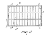
図10〜図12は、本発明による照明パネルの第4実施形態を示す。この最後の実施形態の相違点は、ここでは参照符号37で示すパーティションを、LED8により放射される光の方向に対して直角をなして配されたカニューレを備える蜂か状の本体によって設けた点にある。更に、このパーティションは、パネル本体の各チャンバすなわちカニューレの内側に対角線状に配置されている。各チャンバはそれぞれのLED8に対向している。また、複数のチャンバすなわちカニューレは、LED8の光の伝搬方向に平行に配され、従って、各パーティション37のカニューレに対して直角に配されている。
FIG. 5 is a perspective view of a modification of the second embodiment of the panel shown in FIG. 4, in which the first and second diffusers and the lateral partition are one transparent with a Z-shaped fold. It is formed as a bee-shaped body.
10 to 12 show a fourth embodiment of a lighting panel according to the present invention. The difference of this last embodiment is that the partition indicated here by
ここでは、それぞれのパーティションは、図6〜図9のジクザグの向きに対して直角をなして、パネル本体の前面および後面に対して対角線状にジグザクに配されている。
本発明による両面照明パネルは、照明の均一性を保持しつつ、極めて薄く且つ両面放射を備えて製造することができ、従って、実用上、本発明による両面照明パネルが企図した目的を達成することが分かった。
Here, each partition is arranged in a zigzag pattern diagonally to the front surface and the rear surface of the panel body at a right angle to the zigzag direction in FIGS.
The double-sided lighting panel according to the present invention can be manufactured with extremely thin and double-sided radiation while maintaining the uniformity of illumination, and therefore, in practice, the double-sided lighting panel according to the present invention achieves the intended purpose. I understood.
更に、本発明のパネルは、種々の実施形態において、室内装飾として、また、装飾用途とすると共に空間分離作用を備えて、また、非常口を表示するものとして使用することができる。アウトドア用途に関しては、本パネルは、線路際の看板、広告などとして使用可能である。
この様に創案された照明パネルは、種々に変形可能であり、全ての変形は、特許請求の範囲内に入る。また、詳細部については、技術的に等価の要素により置き換えても良い。
Furthermore, the panel of the present invention can be used as an interior decoration in various embodiments, as a decorative use, provided with a space separation function, and as an emergency exit display. For outdoor use, this panel can be used as signboards and advertisements along the tracks.
The lighting panel thus created can be modified in various ways, and all modifications are within the scope of the claims. Further, the detailed part may be replaced by a technically equivalent element.
実用上、使用材料および形状寸法は、要件および技術水準に応じて如何なるものでもよい。
本願の優先権主張の基礎となるイタリア国特許出願MI2002A000655号の記載をここに引用、合体することとする。
In practice, any materials and geometries may be used depending on requirements and technical level.
The description of Italian patent application MI2002A000655, which is the basis of the priority claim of the present application, is hereby incorporated by reference.
1、23 両面照明パネル
2 第1ディフューザ
3 第2ディフューザ
4、12 チャンバ
5、6 カバー要素
7 パーティション
7a 透明な蜂か状のパネル
8 LED
21 カニューレ
1, 23 Double-
21 Cannula
Claims (19)
側部に支持された一つ以上の光源と、前記チャンバ内に対角線状に配された少なくとも一つのパーティションとを備え、前記パーティションが、前記一つ以上の光源により前記第1及び第2ディフューザ上に放射される光を均一にするようになっていることを特徴とする両面照明パネル。 A double-sided lighting panel comprising first and second diffusers arranged opposite to each other and configured to form at least one chamber closed on the side,
One or more light sources supported on a side, and at least one partition disposed diagonally in the chamber, the partitions being disposed on the first and second diffusers by the one or more light sources. A double-sided illumination panel characterized in that the light radiated to is uniform.
Applications Claiming Priority (2)
| Application Number | Priority Date | Filing Date | Title |
|---|---|---|---|
| IT2002MI000655A ITMI20020655A1 (en) | 2002-03-28 | 2002-03-28 | DOUBLE-SIDED BRIGHT PANEL HAVING UNIFORM LIGHTING |
| PCT/EP2003/002770 WO2003083529A1 (en) | 2002-03-28 | 2003-03-17 | Two-sided illuminated panel with uniform illumination |
Publications (1)
| Publication Number | Publication Date |
|---|---|
| JP2005521993A true JP2005521993A (en) | 2005-07-21 |
Family
ID=11449597
Family Applications (1)
| Application Number | Title | Priority Date | Filing Date |
|---|---|---|---|
| JP2003580906A Pending JP2005521993A (en) | 2002-03-28 | 2003-03-17 | Uniform illumination double-sided lighting panel |
Country Status (9)
| Country | Link |
|---|---|
| US (1) | US7144132B2 (en) |
| EP (1) | EP1488262B1 (en) |
| JP (1) | JP2005521993A (en) |
| CN (1) | CN1321335C (en) |
| AT (1) | ATE487956T1 (en) |
| AU (1) | AU2003219065A1 (en) |
| DE (1) | DE60334892D1 (en) |
| IT (1) | ITMI20020655A1 (en) |
| WO (1) | WO2003083529A1 (en) |
Cited By (4)
| Publication number | Priority date | Publication date | Assignee | Title |
|---|---|---|---|---|
| WO2013015602A2 (en) * | 2011-07-26 | 2013-01-31 | Lg Innotek Co., Ltd. | Lighting module |
| JP2015046291A (en) * | 2013-08-28 | 2015-03-12 | 株式会社インパクト | Lighting device |
| KR101571152B1 (en) * | 2014-07-01 | 2015-11-23 | (주)인크룩스 | Led lighting apparatus |
| KR101862589B1 (en) | 2011-07-26 | 2018-05-30 | 엘지이노텍 주식회사 | Lighting module |
Families Citing this family (15)
| Publication number | Priority date | Publication date | Assignee | Title |
|---|---|---|---|---|
| KR100407528B1 (en) | 2000-09-18 | 2003-11-28 | 아사히 가세이 가부시키가이샤 | Process for producing an oxide catalyst for oxidation or ammoxidation |
| US7632004B2 (en) * | 2004-07-06 | 2009-12-15 | Tseng-Lu Chien | LED night light with more than 1 optics means |
| EP1891620B1 (en) * | 2005-05-31 | 2009-09-02 | Koninklijke Philips Electronics N.V. | Light-source with fabric diffusing layer |
| US20080037287A1 (en) * | 2006-08-14 | 2008-02-14 | Robert Michael Krohn | Backlight panel and manufacturing method thereof |
| US8328391B2 (en) * | 2005-12-07 | 2012-12-11 | Koninklijke Philips Electronics N.V. | Lighting module |
| US7481563B2 (en) | 2006-09-21 | 2009-01-27 | 3M Innovative Properties Company | LED backlight |
| RU2398679C2 (en) * | 2007-07-30 | 2010-09-10 | Сергей Александрович Запольский | Method of fabricating art and decorative panels (versions) |
| KR101720929B1 (en) | 2008-12-09 | 2017-03-29 | 코닌클리케 필립스 엔.브이. | Lighting system with fiber diffusing element |
| US20110271558A1 (en) * | 2010-05-06 | 2011-11-10 | Skechers U.S.A., Inc. Ii | Lighted panel for an article of footwear |
| SE534994C2 (en) * | 2010-07-28 | 2012-03-06 | Anders Rensmo | light plate |
| US8845174B2 (en) * | 2011-08-23 | 2014-09-30 | Nicholas Jackson | Energy-efficient lighting panel |
| CN103765263B (en) * | 2011-09-06 | 2018-04-03 | 飞利浦灯具控股公司 | Luminescent panel with transparent honeycomb shape support panel |
| KR101269135B1 (en) * | 2011-10-31 | 2013-05-29 | 김종율 | A Skin Picturing Device |
| EP2863114B1 (en) * | 2013-10-16 | 2017-04-26 | Bega Gantenbrink-Leuchten KG | LED area light |
| FR3084926B1 (en) * | 2018-08-09 | 2021-05-07 | Display Light | ULTRAPLATE LIGHTING SLAB |
Family Cites Families (11)
| Publication number | Priority date | Publication date | Assignee | Title |
|---|---|---|---|---|
| DE868694C (en) * | 1951-03-01 | 1953-02-26 | Alexander Dr Ringleb | Device for increasing the uniformity and luminance through translucent areas of light passing through |
| EP0375293A3 (en) * | 1988-12-15 | 1991-01-02 | Tama Denki Kogyo Kabushiki Kaisha | Back-lighting apparatus for screen |
| DE4037076C1 (en) * | 1990-11-22 | 1992-04-02 | Dambach-Werke Gmbh, 7560 Gaggenau, De | Lightweight lighting box giving uniform beam - including transparent, wedge-shaped reflecting member directed towards illuminating member, etc. |
| GB9212727D0 (en) * | 1992-06-16 | 1992-07-29 | Secr Defence | Radiation coupling device |
| US5345325A (en) * | 1993-03-31 | 1994-09-06 | Rockwell International Corporation | Sculptured light diffuser for enhancing brightness and uniformity of liquid crystal displays |
| US5673999A (en) * | 1994-12-12 | 1997-10-07 | Norand Corporation | LCD backlighting method and apparatus using a xenon flash tube including drive circuit |
| CN2225714Y (en) * | 1995-06-20 | 1996-04-24 | 曾超宁 | Light conductive illumination display board |
| CN2279672Y (en) * | 1996-07-04 | 1998-04-22 | 李嘉钰 | Thin plate lamp box |
| US7077536B2 (en) * | 2000-01-19 | 2006-07-18 | Apostol Konomi | Double-sided edge lighting-type display light box |
| JP2002056989A (en) * | 2000-08-11 | 2002-02-22 | Seiko Epson Corp | Light-emission device |
| US6971758B2 (en) * | 2001-03-16 | 2005-12-06 | Toyoda Gosei Co., Ltd. | Illumination device |
-
2002
- 2002-03-28 IT IT2002MI000655A patent/ITMI20020655A1/en unknown
-
2003
- 2003-03-17 CN CNB038071355A patent/CN1321335C/en not_active Expired - Fee Related
- 2003-03-17 JP JP2003580906A patent/JP2005521993A/en active Pending
- 2003-03-17 DE DE60334892T patent/DE60334892D1/en not_active Expired - Lifetime
- 2003-03-17 AU AU2003219065A patent/AU2003219065A1/en not_active Abandoned
- 2003-03-17 AT AT03714837T patent/ATE487956T1/en not_active IP Right Cessation
- 2003-03-17 WO PCT/EP2003/002770 patent/WO2003083529A1/en active Application Filing
- 2003-03-17 US US10/507,477 patent/US7144132B2/en not_active Expired - Fee Related
- 2003-03-17 EP EP03714837A patent/EP1488262B1/en not_active Expired - Lifetime
Cited By (6)
| Publication number | Priority date | Publication date | Assignee | Title |
|---|---|---|---|---|
| WO2013015602A2 (en) * | 2011-07-26 | 2013-01-31 | Lg Innotek Co., Ltd. | Lighting module |
| WO2013015602A3 (en) * | 2011-07-26 | 2013-04-11 | Lg Innotek Co., Ltd. | Lighting module |
| US9880345B2 (en) | 2011-07-26 | 2018-01-30 | Lg Innotek Co., Ltd. | Lighting module |
| KR101862589B1 (en) | 2011-07-26 | 2018-05-30 | 엘지이노텍 주식회사 | Lighting module |
| JP2015046291A (en) * | 2013-08-28 | 2015-03-12 | 株式会社インパクト | Lighting device |
| KR101571152B1 (en) * | 2014-07-01 | 2015-11-23 | (주)인크룩스 | Led lighting apparatus |
Also Published As
| Publication number | Publication date |
|---|---|
| ITMI20020655A0 (en) | 2002-03-28 |
| EP1488262A1 (en) | 2004-12-22 |
| AU2003219065A1 (en) | 2003-10-13 |
| WO2003083529A1 (en) | 2003-10-09 |
| EP1488262B1 (en) | 2010-11-10 |
| DE60334892D1 (en) | 2010-12-23 |
| CN1321335C (en) | 2007-06-13 |
| ATE487956T1 (en) | 2010-11-15 |
| ITMI20020655A1 (en) | 2003-09-29 |
| US7144132B2 (en) | 2006-12-05 |
| CN1643411A (en) | 2005-07-20 |
| US20050122716A1 (en) | 2005-06-09 |
Similar Documents
| Publication | Publication Date | Title |
|---|---|---|
| JP2005521993A (en) | Uniform illumination double-sided lighting panel | |
| US7748148B2 (en) | Display sign adapted to be backlit by widely spaced light emitting diodes | |
| US9121982B2 (en) | Light-emitting device for emitting diffuse light | |
| JP5420415B2 (en) | Flat thin LED lighting device | |
| JP2005331969A (en) | Back illumination to be used for display unit | |
| US5149191A (en) | Combination louver/lens light fixture shield | |
| AU762579B2 (en) | Light with a light-guiding element | |
| US20160258615A1 (en) | Acoustic lighting tile | |
| US4425603A (en) | Indirect light-distributing ceiling fixtures with alternate reflector array | |
| KR920002983A (en) | Luminaire with profile intensity reflector of uniform intensity | |
| EP3626425B1 (en) | Lamp component for forming a lamp having a large emission angle, lamp and method for manufacturing such a lamp component | |
| JP2008539545A (en) | Lighting apparatus and lighting panel for lighting apparatus | |
| US3866036A (en) | Fluorescent fixture with optical device | |
| KR910014652A (en) | Lighting device for elevator cage | |
| NO175399B (en) | Diffuser for use in advertising / information boards | |
| CN111527346B (en) | Lighting module and lighting kit | |
| CN216595585U (en) | Optical lens and lamp | |
| JP2009252447A (en) | Light guide, illuminating device, and display device | |
| JP2004302028A (en) | Display device and guiding light device | |
| JP2016100317A (en) | Daylighting system | |
| KR100984191B1 (en) | Sectional transparent arcylic panel and light emitting diode illumination signboard using the same | |
| CN212537620U (en) | Side light-emitting panel lamp with grille | |
| JP2009110804A (en) | Panel light source | |
| JPH03214501A (en) | Wall illuminating device | |
| JP2008210567A (en) | Surface color developing device |
Legal Events
| Date | Code | Title | Description |
|---|---|---|---|
| A621 | Written request for application examination |
Free format text: JAPANESE INTERMEDIATE CODE: A621 Effective date: 20060206 |
|
| A977 | Report on retrieval |
Free format text: JAPANESE INTERMEDIATE CODE: A971007 Effective date: 20080819 |
|
| A131 | Notification of reasons for refusal |
Free format text: JAPANESE INTERMEDIATE CODE: A131 Effective date: 20080827 |
|
| A02 | Decision of refusal |
Free format text: JAPANESE INTERMEDIATE CODE: A02 Effective date: 20090218 |