US185643A - Improvement in draw-bars for railway-cars - Google Patents
Improvement in draw-bars for railway-cars Download PDFInfo
- Publication number
- US185643A US185643A US185643DA US185643A US 185643 A US185643 A US 185643A US 185643D A US185643D A US 185643DA US 185643 A US185643 A US 185643A
- Authority
- US
- United States
- Prior art keywords
- draw
- bars
- railway
- bar
- cars
- Prior art date
- Legal status (The legal status is an assumption and is not a legal conclusion. Google has not performed a legal analysis and makes no representation as to the accuracy of the status listed.)
- Expired - Lifetime
Links
- XEEYBQQBJWHFJM-UHFFFAOYSA-N iron Chemical compound [Fe] XEEYBQQBJWHFJM-UHFFFAOYSA-N 0.000 description 4
- 238000010276 construction Methods 0.000 description 2
- 229910052742 iron Inorganic materials 0.000 description 2
- 239000000463 material Substances 0.000 description 2
- 238000007747 plating Methods 0.000 description 2
- 238000004080 punching Methods 0.000 description 2
Images
Classifications
-
- B—PERFORMING OPERATIONS; TRANSPORTING
- B61—RAILWAYS
- B61G—COUPLINGS; DRAUGHT AND BUFFING APPLIANCES
- B61G9/00—Draw-gear
- B61G9/12—Continuous draw-gear combined with buffing appliances, e.g. incorporated in a centre sill
- B61G9/125—Continuous draw-gear combined with buffing appliances, e.g. incorporated in a centre sill with only metal springs
Definitions
- My invention relates to that class of railway-car draft-connections in which the drawheads at the opposite ends of the car are connected together independently of the frame or body of the car.
- the frame of an ordinary car-body is represented at A.
- the usual bolsters are shown at B, the bolster-plates atb, and the king-bolt at c.
- Any desired pattern or style of drawhead D may be employed, and these aud other devices used in connection therewith are, except as hereinafter stated, of any desired style or construction.
- the draw-head D at the opposite ends of the car are connected directly together by a draw-bar, a al, secured at its ends to the draw-heads by keys d, the drawheads being backed by the usual, or any desired, arrangement of springs d'.
- the drawbar a al is preferably made of round or polygonal iron, which, where it passes the bolsters B, is flattened down, as at c, through a length equal to the breadth of bolster B or bolsterplate b, plus the amount of end play for which provision is or ought to be made.
- the object of thus flattening down the draw-bar is, that as the bolster B must be recessed for the passage ofthe bar, a round or polygonal bar would require so deep a recess as to weaken seriously the strength of' the bolster, while with a lattened bar the recess need not be so deep as to lessen to any serious extent the supporting power of the bolster.
- a slot, c' is punched in this dattened part, through which the king-bolt e passes. The object of the slot is to make provision for the end play of the draw-bar.
Description
A. MILLIKEN.
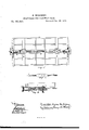
i DRAW-BARS Fon RAILWAY CARS. N.185,643, Patented Dec. 26,1875.
Wmss as /nv @Kw Mew WLM Kw4 QP/mvwem-gw/L' THE GRAPHIC GOJLY UNITED STATES PATENT OEEcEla ANDREW MILLIKEN, OF PITTSBURG, PENNSYLVANIA.
IMPROVEMENT IN DRAW-BARS FOR RAILWAY-CARS.
Speciication forming part of Letters Patent No. 185,643, dated December 26, 1876; application filed November 18, 1876.
To all 'whom t may concern Be it known that I, ANDREW MILLIKEN, of Pittsburg, county of Allegheny, State of Pennsylvania, have invented or discovered a new and useful Improvement in Draw-Bars for Railway-Gars; and I do hereby declare the following to be a full, clear, concise, and exact description thereof, reference being had to the accompanying drawing, making a part of this specification, iu whichlike letters indicating like parts- Figure lis a bottom view of the frame of' a car-body, showing my improvements as applied thereto. Fig. 2 is an enlarged sectional view in the linea/:x of Fig. 1, and Fig. 3 is an enlarged plan view of one end of the drawbar.
My invention relates to that class of railway-car draft-connections in which the drawheads at the opposite ends of the car are connected together independently of the frame or body of the car.
The frame of an ordinary car-body is represented at A. The usual bolsters are shown at B, the bolster-plates atb, and the king-bolt at c. Any desired pattern or style of drawhead D may be employed, and these aud other devices used in connection therewith are, except as hereinafter stated, of any desired style or construction. The draw-head D at the opposite ends of the car are connected directly together by a draw-bar, a al, secured at its ends to the draw-heads by keys d, the drawheads being backed by the usual, or any desired, arrangement of springs d'. The drawbar a al is preferably made of round or polygonal iron, which, where it passes the bolsters B, is flattened down, as at c, through a length equal to the breadth of bolster B or bolsterplate b, plus the amount of end play for which provision is or ought to be made. The object of thus flattening down the draw-bar is, that as the bolster B must be recessed for the passage ofthe bar, a round or polygonal bar would require so deep a recess as to weaken seriously the strength of' the bolster, while with a lattened bar the recess need not be so deep as to lessen to any serious extent the supporting power of the bolster. A slot, c', is punched in this dattened part, through which the king-bolt e passes. The object of the slot is to make provision for the end play of the draw-bar.
In case the punching of the slot removes too much material, and seriously weakens the bar at this point, the difculty may be met by the usual operations of plating or upsetting. Continuous draw-bars are not new; but when made in a single piece, as has usually been done, it involves considerable labor and expense to renew them.
To lessen such labor and expense, I make the draw-bar in two pieces, a, al, and joint or unite their adjacent ends by means of a tapped socket, a2, screwing onto them by right and let't hand threads. Then, if either end breaks, it is much more easily and cheaply replaced than if it were made in one continuous length, and With a great saving in respect to loss of service; and as regards breakage, the slot c is an important element, since in case the bar a a1 breaks between the slots, as will oftenest be the case, the base of each slot will th'en engage its king-bolt, and the car can complete its trip.
I claim herein as my inventionl. A continuous draw-bar, liattened and slotted, as at c c', in combination with recessed bolster B and king-bolt e, substantially as set forth.
2. The jointed draw-bar a al a2, flattened and slotted where it passes the bolster, in combination with the king-bolts e, substantially as set forth.
In testimony whereof I have hereunto set my hand.
ANDREW MILMKEN. Witnesses:
J. J. McGoRMrcK, GLAUDIUs L. PARKER.
Publications (1)
| Publication Number | Publication Date |
|---|---|
| US185643A true US185643A (en) | 1876-12-26 |
Family
ID=2255049
Family Applications (1)
| Application Number | Title | Priority Date | Filing Date |
|---|---|---|---|
| US185643D Expired - Lifetime US185643A (en) | Improvement in draw-bars for railway-cars |
Country Status (1)
| Country | Link |
|---|---|
| US (1) | US185643A (en) |
-
0
- US US185643D patent/US185643A/en not_active Expired - Lifetime
Similar Documents
| Publication | Publication Date | Title |
|---|---|---|
| US185643A (en) | Improvement in draw-bars for railway-cars | |
| US583548A (en) | Car-coupling | |
| US415194A (en) | Car-coupling | |
| US731520A (en) | Car-coupling. | |
| US454754A (en) | Carrying-iron for gar-couplings | |
| US1344185A (en) | Wear-plate for car-couplings | |
| US394745A (en) | Car-coupling | |
| US262808A (en) | Thomas f | |
| US1136079A (en) | Draft-gear attachment. | |
| US384840A (en) | Car-coupling | |
| US176099A (en) | Improvement in car-couplings | |
| US695619A (en) | Car-coupling. | |
| US565025A (en) | Car-coupling | |
| US784889A (en) | Car-coupling. | |
| US426786A (en) | Car-coupling | |
| US698970A (en) | Car-coupling. | |
| US163743A (en) | Improvement in car-coupling links | |
| US949798A (en) | Car draft-rigging. | |
| US638284A (en) | Car-coupling. | |
| US566550A (en) | James timms | |
| US1265018A (en) | Draw-bar attachment. | |
| US369975A (en) | westbbook | |
| US1202746A (en) | Underframe for railway-cars. | |
| US1039403A (en) | Cast-steel underframe for cars. | |
| US615561A (en) | John mackey larkin |