US1856075A - Vehicle - Google Patents
Vehicle Download PDFInfo
- Publication number
- US1856075A US1856075A US360512A US36051229A US1856075A US 1856075 A US1856075 A US 1856075A US 360512 A US360512 A US 360512A US 36051229 A US36051229 A US 36051229A US 1856075 A US1856075 A US 1856075A
- Authority
- US
- United States
- Prior art keywords
- vehicle
- wheels
- wheel
- shafts
- driving
- Prior art date
- Legal status (The legal status is an assumption and is not a legal conclusion. Google has not performed a legal analysis and makes no representation as to the accuracy of the status listed.)
- Expired - Lifetime
Links
- 230000008878 coupling Effects 0.000 description 5
- 238000010168 coupling process Methods 0.000 description 5
- 238000005859 coupling reaction Methods 0.000 description 5
- 230000033001 locomotion Effects 0.000 description 4
- 230000005540 biological transmission Effects 0.000 description 3
- 238000010276 construction Methods 0.000 description 2
- 235000010627 Phaseolus vulgaris Nutrition 0.000 description 1
- 244000046052 Phaseolus vulgaris Species 0.000 description 1
- 229940000425 combination drug Drugs 0.000 description 1
- 239000000428 dust Substances 0.000 description 1
- 238000007689 inspection Methods 0.000 description 1
- 230000000717 retained effect Effects 0.000 description 1
Images


Classifications
-
- B—PERFORMING OPERATIONS; TRANSPORTING
- B60—VEHICLES IN GENERAL
- B60K—ARRANGEMENT OR MOUNTING OF PROPULSION UNITS OR OF TRANSMISSIONS IN VEHICLES; ARRANGEMENT OR MOUNTING OF PLURAL DIVERSE PRIME-MOVERS IN VEHICLES; AUXILIARY DRIVES FOR VEHICLES; INSTRUMENTATION OR DASHBOARDS FOR VEHICLES; ARRANGEMENTS IN CONNECTION WITH COOLING, AIR INTAKE, GAS EXHAUST OR FUEL SUPPLY OF PROPULSION UNITS IN VEHICLES
- B60K17/00—Arrangement or mounting of transmissions in vehicles
- B60K17/34—Arrangement or mounting of transmissions in vehicles for driving both front and rear wheels, e.g. four wheel drive vehicles
Definitions
- the present invention refers to vehicles, especially motor-driven vehicles, such as motor cars and the like, and the invention sub stantially aims at such an arrangement oi the Wheels that each wheel may, independently of the others, follow the irregularities of the road individually, so that the vehicle obtains, when in motion, softer and more tlex ible movements than vehicles of the construetion hitherto known.
- the invention refers to means for transmitting power to the driving vvheels from a motor disposed on the vehicle, and to this end one object of the invention is to provide power transmission to such driving wheels which for the purpose ot' bringing about soft and uniform movements of the vehicle in its propulsion are arranged in the vehicle in such manner that each driving Wheel may follow the irregularities of the road individually, independently of the other Wheels.
- the invention also relates to an arrange nient for resilient supporto one or more of the Wheel axles of the vehicle, and to this end a further object of the invention is to.
- the invention principall consists in that one or tivo parallel shafts riven by theme-l tor are in connection with shafts coupled to ⁇ the driving Wheels, substantially at right angles to the latter, by means of worm gearings or toothed gearings, each driving Wheel being rotatably mounted with its coupling shaft in a special part consisting referably of a frame or the like, said part eing pivotally connected with the vehicleabout an axis coin-v ciding substantially with the driving shaft in question.
- the arrangement is also applicable for power transmission onto suchdriving wheels which have their axles swingably arranged in the horizontal plane in order to facilitate steering of the vehicle.
- connection between each of such Wheel axles and the vehicle according to the invention consists of two springs secured to the chassis of the vehicle and extending each on one side of the Wheels in question.
- Such an arrangement of the Wheels brings about the advantage that the vehicle obtains a softer and more flexible motion than such vehicles which are in known manner provided with Wheels arranged each at one end of the axle in question, besidesiwhich the arrangement involves a considerable simplification from the point of view of construction, such simplification making it possible, particularly in motor-driven vehicles, that the non-driven Wheels may be provided with supporting means of the type hereinbefore stated, so that the invention could be advantageously applied to the supporting means for the axles of the rear wheels, for instance, in motor vehicles propelled by the front Wheels.
- Fig. 1 is a plan view of the underfame or chassis of a motor car with kdriven' front wheels, the rear wheels being supported by resilient means according to the invention.
- Fig. 2 is a front view and Fig. 3 anelevation thereof.
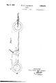
- Fig. 4 is a section to an enlarged scale on line 4-4 in Fig. 2, and
- Fig. is a section on line 5-5 in Fig. 1, likewise on a larger scale.
- a motor 2 Provided on the underframe 1 of the vehicle for the propulsion thereof is a motor 2, the crank shaft of which is connected by a v gear box with two shafts 3 mounted each on one side of the motor, in the longitudinal direction of the vehicle, said shafts 3 being rotatable by means of toothed wheels 4 or the like secured on the ends thereof.
- the other end of the shaft is provided with a bevel gear 5, see Fig.
- Thepart 9 is formed at the toothed gearing into a casing 11 enclosing the same, and in order to secure rigid mounting in the vehicle, it is formed into a pin 13 guided by the bearingS as well as by a second bearing 12 preferably secured on the motor frame. Moreover, the said pin 13 is provided with a flange-14 bearing against the one side of the bearing 8 so asto x the part 8 in the axial direction, as well as with a spring 15 arranged between the opposite side of the bearing and the casing 11.
- the resilient connection between the wheels and the vehicle is obtained by the spring 16, see Fig. 2, transversely arranged underneath the parts 9, said spring 16 being secured at its center to the underframe 1 ofthe vehicle and with its ends to the outer ends of the parts9 by means of links 17.
- This latter arrangement consists of a cross piece 19, see Fig.l 5, preferably T-shaped'and pivotally mounted in the 'horizontal plane at the outer end of the part 9, the web portion of said cross piece being for this purpose formed into a stud 20, on which the driving wheel 18 is rotatably arranged, while the two remaining portions are formed into studs 22 mounted in bushings 21 secured in the frame part 9.
- the free end of the coupling shaft 7 is connected to the driving wheel 18 by means of bevel gears, two equal-sized gears 23 both of which are rotatably mounted about the studs 22 of the cross piece and adapted .to engage a toothed wheel 24 secured on the free end of the coupling shaft 7, and also to engage a toothed, wheel 25 connected with the driving wheel.
- the cross piece and the gearings are enclosed by a casing formed in the frame part 9, said casing being preferably of a hemispherical main shape and covered by a cover 26 of the same shape, the casing and its cover being moreover arranged together to form an attachment for the bushings 21 carrying the cross piece 19, said bushings being also arranged to guide the cross piece in the vvertical direction, for instance by means of a flange 27 arranged on the cross piece.
- the one stud 22 of thc cross piece is made longer than the other so as to reach outside the one bushing, preferably the upper one, where it forms an attachmentfor an arm 28 which may in known manner be connected with the steering gear of the vehicle.
- the driving wheel 18 is connected with the bevel gear 25 by means of a bushing 29 rotatably arranged on the stud of the cross piece, said bushing having also secured thereto a dished member 30 bearing on the inside against the cover 26, which member 30 is adapted to bring about tightening of an opening 31, see Fig. 4, provided in'the'cover 26 to facilitate swinging of the cross piece, whereby the gearings arranged within the casing may be kept enclosed against the access of dust and oil.
- the dished tightening member 30 may either be so arranged as to take part in the rotation, as shown in the drawings, or may be so arranged that the lbushing 29 moves freelyv therein.
- a protecting plate 30' preferably dish-shaped ⁇ may be secured to the Wheel 18, said plate bearing without any appreciable friction against the outside ol' the cover 26, forming a tight it'therewith.
- the braking meansl for cach wheel is preferably arranged at the driving shaft 3 by means of a disk 32 secured ou the one end of a shaft, said disk being adapted to be actuated by braking devices of any suitable, previously known construction.
- The' connection between the steering device provided on the vehicle and the arms'28 secured on the one stud end of the cross piece 19 comprises link rods 33 or thelike and is. moreover, so arranged that in steering the wheels 18 adjust themselves relatively to each other in the manner desired.
- the cross piece with the gear wheels 25 and the guiding wheel 18 mounted on the web portion 20 thereof will thus turn about the studs 22 of the cross piece and about the gear wheels 23 arranged concentrically therewith, so that the tooth engagement between the gear wheels 23 and 25 is retained independently 'of the position which the driving' wheel is caused to assume.
- the distance between the cross piece studs 22 and the center of the wheel path, designated by X in the drawings, may be given a suitable value, it' the wheel 18 is shaped in accordance therewith. .F or instance, the value of X may be selected so as to approach'zero, in which case the power required for the steering of the vehicle is believed to have its minimum value.
- the toothed Wheels 23 should be provided with doubled tooth rims, besides which the arrangement ot two toothed wheels E23 rnoving 'freely on the studs of the cross piece may, although preferable from the pointof view ot operation, be replaced by a single toothed wheel 23 involving the saine etlect.
- the 'lightening ot the opening 31 provided in the cover oi the casing' may also be brought about by arranging the tightening member 30 carried by the 'Wheel anle 20 to enclose the outside of the casing arranged at the end ot the traine part 9 while bearing thereagainst 'with a tight lit.
- 'lha invention is applicable not only in trent wheel driven vehicles, but also to drive the rear wheels ofthe vehicle and, besides, in such cases whereall Wheels of the vehicle are to be driven two, four or all wheel axles may then be sivingably arranged in the horiw aontal plane to bring about steerin of the vehiclein the saine way as shown at t e front wheels.
- a motor driven vehicle an arrangeinent'ifor transmitting; power from the motor to the driving wheels, including the combi nation, with a pair ot substantially parallel drive shafts driven by the motor and disposed in lthe longitudinal direction of the vehicle and a transversely directed shaft arranged for each driving wheel, of a bearing member provided for each of said transverse- 1y directed shafts and pivoted upon said vehicle so as to be individually swin said parallel drive shafts, there being means including gearing respectlvely interposed between each of said transversely directed shafts and the corresponding drive shafts for individually driving said first shafts.
- an arrangement for transmitting power from the motor to the driving wheels including the combination, with a pair of spaced similar drive shafts driven by the motor and disposed gen erally in the longitudinal direction of the vehicle and a transversely directed shaft arranged for each driving Wheel, of a bearing member provided foreach of said transversel ly. directed shafts and individually pivoted so as to be swingable upon respective axes coinciding with the axes of said parallel drive shafts, there being means including gearin respectively interposed between each of sai transversely directed shafts and the correspondinff drive shafts for individually driving said irst shafts.
- a motor driven vehicle an arrange? nient for transmitting power from the motor to the driving' wheels, including the combination, with a pair of spaced similar drive shatts driven by the motor and disposed generally in the longitudinal direction of the vehicle and a transversely directed shaft ar ranged lor each drivingA wheel, of a bearing nicniber provided :tor each of said transverse ly directed shafts and individually pivoted so as to be swingable uponrespective axes coinciding with the axes of said spaced drive shalts, 'a ⁇ pair ot cross pieces' individually pivoted to the outer end of each of said bearing members so as to swivel about a vertical axis thereon and steering means upon said vehicle connected to said cross pieces :for the purpose et lturningl the same and the respective driving wheels associated therewith at will, there being' means including gearing l respectively interposed between each ot said p interposed between each of said transversely directed shafts and the respective drive
- a motor driven vehicle an arrangement for transmitting power from the motor to the driving wheels, including the combination, with a drive shafts driven by the motor and disposed in the longitudinal direction of the vehicle and a transversely directed shaft ar ranged for each driving wheel, of a"bearing member provided for each' of said trans pair of, substantially parallel le able upon i respectlvevaxes coinciding with t 1e axes of dit lila
Landscapes
- Engineering & Computer Science (AREA)
- Chemical & Material Sciences (AREA)
- Combustion & Propulsion (AREA)
- Transportation (AREA)
- Mechanical Engineering (AREA)
- Arrangement Or Mounting Of Propulsion Units For Vehicles (AREA)
Description
May 3, 1932 E. R. M HoLMQulsT 1,856,075
n VEHICLE Filed May 4, 1929 3 Sheets-Sheet l 1r l f n1 tf1- JL. M L' JL J A770/P/VEY May 3, 1932 E. R. Mi HoLMoulsr VEHICLE Filed May 4, 1929 3 Sheets-Sheet A r mm/EV May 3, 1932 E. R. M, HoLMQursT 1,856,075'
VEHICLE Filed May 4, 1929 3 Sheets-Sheet 3 ArbiP/vfy Patented May 3, 1932 ERNST RUDOLF MAGNUS HOLMQUIST, 0F LILLA EDET, $WEDEN` 'VEHICLE Application led May 4, 1929, Serial No. 360,512, and in Sweden March 11, 1929.
The present invention refers to vehicles, especially motor-driven vehicles, such as motor cars and the like, and the invention sub stantially aims at such an arrangement oi the Wheels that each wheel may, independently of the others, follow the irregularities of the road individually, so that the vehicle obtains, when in motion, softer and more tlex ible movements than vehicles of the construetion hitherto known.
More particularly, the invention refers to means for transmitting power to the driving vvheels from a motor disposed on the vehicle, and to this end one object of the invention is to provide power transmission to such driving wheels which for the purpose ot' bringing about soft and uniform movements of the vehicle in its propulsion are arranged in the vehicle in such manner that each driving Wheel may follow the irregularities of the road individually, independently of the other Wheels. Y
The invention also relates to an arrange nient for resilient supporto one or more of the Wheel axles of the vehicle, and to this end a further object of the invention is to.
provide a resilient connection between the vehicle and the Wheel axles of such a nature that the arranvfement of each Wheel per se in the chassis olj the vehicle is, facilitated, due regard being taken to the condition that the arrangement of the Wheel axles at the springs must be such as to ensure asupport of the Wheels which is sufficiently strong .to with-r stand, among other things, lateral strains and the like. y g
The invention principall consists in that one or tivo parallel shafts riven by theme-l tor are in connection with shafts coupled to` the driving Wheels, substantially at right angles to the latter, by means of worm gearings or toothed gearings, each driving Wheel being rotatably mounted with its coupling shaft in a special part consisting referably of a frame or the like, said part eing pivotally connected with the vehicleabout an axis coin-v ciding substantially with the driving shaft in question.
The arrangement is also applicable for power transmission onto suchdriving wheels which have their axles swingably arranged in the horizontal plane in order to facilitate steering of the vehicle.
To bring about a resilient connection between the vehicle and one or more of the wheel axles thereof, the connection between each of such Wheel axles and the vehicle according to the invention consists of two springs secured to the chassis of the vehicle and extending each on one side of the Wheels in question.
Such an arrangement of the Wheels brings about the advantage that the vehicle obtains a softer and more flexible motion than such vehicles which are in known manner provided with Wheels arranged each at one end of the axle in question, besidesiwhich the arrangement involves a considerable simplification from the point of view of construction, such simplification making it possible, particularly in motor-driven vehicles, that the non-driven Wheels may be provided with supporting means of the type hereinbefore stated, so that the invention could be advantageously applied to the supporting means for the axles of the rear wheels, for instance, in motor vehicles propelled by the front Wheels.
Arrangements should then be made to render the Wheels accessible for inspection, dismantling, repair or the like, preferably by the one of the springs provided each on one side of the Wheels in question being remov- [ably attached to the wheel axle and, besides, varranged to be removed from the Wheel in y such a manner as to render the `latter accessible from the one side, which arrangement may be simply carried into e'ect, for instance, by having the removable springs secured eitherin a displaceable or rotary inannervto the chassis `of the vehicle.
The invention is illustrated on the accompanying drawings. Fig. 1 is a plan view of the underfame or chassis of a motor car with kdriven' front wheels, the rear wheels being supported by resilient means according to the invention. Fig. 2 is a front view and Fig. 3 anelevation thereof. Fig. 4 is a section to an enlarged scale on line 4-4 in Fig. 2, and
Fig. is a section on line 5-5 in Fig. 1, likewise on a larger scale.
Provided on the underframe 1 of the vehicle for the propulsion thereof is a motor 2, the crank shaft of which is connected by a v gear box with two shafts 3 mounted each on one side of the motor, in the longitudinal direction of the vehicle, said shafts 3 being rotatable by means of toothed wheels 4 or the like secured on the ends thereof. The other end of the shaft is provided with a bevel gear 5, see Fig. 4, engaging another similar toothed wheel 6 arranged to drive a coupling shaft 7 connected to the one front wheel and extending substantially at right angles to the shaft 3, said shaft 7 being rotatably mounted in a part 9 arranged in the vehicle and rotatable or swingable in a bearing 8i about an axis coinciding with the shaft 3, said part 9being provided with a stay 10 to make provision for means -to withstand strains or the like,A which stay 10 is secured vwith its one end to the outer end of the part 9, while being 'arranged with its other end, by means of a ball and socket joint, in the underframe of the vehicle, at a point situated on the centre line of the shaft 3. Thepart 9 is formed at the toothed gearing into a casing 11 enclosing the same, and in order to secure rigid mounting in the vehicle, it is formed into a pin 13 guided by the bearingS as well as by a second bearing 12 preferably secured on the motor frame. Moreover, the said pin 13 is provided with a flange-14 bearing against the one side of the bearing 8 so asto x the part 8 in the axial direction, as well as with a spring 15 arranged between the opposite side of the bearing and the casing 11. The resilient connection between the wheels and the vehicle is obtained by the spring 16, see Fig. 2, transversely arranged underneath the parts 9, said spring 16 being secured at its center to the underframe 1 ofthe vehicle and with its ends to the outer ends of the parts9 by means of links 17. By means of the springs 16, the stays 10 and the mount- v ing arrangements 8 and 12 of the part 9 pivotally connectedwith the vehicle, a reliable andresilient connection is obtained between the wheels and the chassis of the vehicle, said connection being capable of withstanding strains, which is of great importance Whether the coupling shaft 7 be directly connected to the driving wheel 18 or whether the shaft carrying the wheel 18 be swing'ably arranged in thev horizontal plane to `facilitate steering of the vehicle by means of the wheels.
This latter arrangement consists of a cross piece 19, see Fig.l 5, preferably T-shaped'and pivotally mounted in the 'horizontal plane at the outer end of the part 9, the web portion of said cross piece being for this purpose formed into a stud 20, on which the driving wheel 18 is rotatably arranged, while the two remaining portions are formed into studs 22 mounted in bushings 21 secured in the frame part 9. The free end of the coupling shaft 7 is connected to the driving wheel 18 by means of bevel gears, two equal-sized gears 23 both of which are rotatably mounted about the studs 22 of the cross piece and adapted .to engage a toothed wheel 24 secured on the free end of the coupling shaft 7, and also to engage a toothed, wheel 25 connected with the driving wheel. The cross piece and the gearings are enclosed by a casing formed in the frame part 9, said casing being preferably of a hemispherical main shape and covered by a cover 26 of the same shape, the casing and its cover being moreover arranged together to form an attachment for the bushings 21 carrying the cross piece 19, said bushings being also arranged to guide the cross piece in the vvertical direction, for instance by means of a flange 27 arranged on the cross piece. The one stud 22 of thc cross piece is made longer than the other so as to reach outside the one bushing, preferably the upper one, where it forms an attachmentfor an arm 28 which may in known manner be connected with the steering gear of the vehicle.
W'ith respect to the mounting, the driving wheel 18 is connected with the bevel gear 25 by means of a bushing 29 rotatably arranged on the stud of the cross piece, said bushing having also secured thereto a dished member 30 bearing on the inside against the cover 26, which member 30 is adapted to bring about tightening of an opening 31, see Fig. 4, provided in'the'cover 26 to facilitate swinging of the cross piece, whereby the gearings arranged within the casing may be kept enclosed against the access of dust and oil. The dished tightening member 30 may either be so arranged as to take part in the rotation, as shown in the drawings, or may be so arranged that the lbushing 29 moves freelyv therein. Moreover, a protecting plate 30', preferably dish-shaped` may be secured to the Wheel 18, said plate bearing without any appreciable friction against the outside ol' the cover 26, forming a tight it'therewith. The braking meansl for cach wheel is preferably arranged at the driving shaft 3 by means of a disk 32 secured ou the one end of a shaft, said disk being adapted to be actuated by braking devices of any suitable, previously known construction. f
The' connection between the steering device provided on the vehicle and the arms'28 secured on the one stud end of the cross piece 19 comprises link rods 33 or thelike and is. moreover, so arranged that in steering the wheels 18 adjust themselves relatively to each other in the manner desired. In this operation, the cross piece with the gear wheels 25 and the guiding wheel 18 mounted on the web portion 20 thereof will thus turn about the studs 22 of the cross piece and about the gear wheels 23 arranged concentrically therewith, so that the tooth engagement between the gear wheels 23 and 25 is retained independently 'of the position which the driving' wheel is caused to assume.
As the turning moment produced in driving and braking the Wheels 18 will be coun-- teracted by a moment exerted by the link rods 33, it is of importance that this Inoinent he made as small as possible. According to the prevalent conditions, the distance between the cross piece studs 22 and the center of the wheel path, designated by X in the drawings, may be given a suitable value, it' the wheel 18 is shaped in accordance therewith. .F or instance, the value of X may be selected so as to approach'zero, in which case the power required for the steering of the vehicle is believed to have its minimum value.
rll`he embodiment described may be varied and completed in many respects in regard to inost of the detail arrangements. Thus, for instance, all shafts have been fitted with triction bearings, according to the drawings, but it is evident that the mounting of the shafts on balls or rollers is much to be preterred from the point of view ot -friction. Moreover, the toothed gearings all over have been shown as provided with a ratio ot l t l,
i while it is possible also to use other ratios both in the transmission between the shafts i l and 7, and between the shafts 7 and the driving wheel, in which latter case, however, 'the toothed Wheels 23 should be provided with doubled tooth rims, besides which the arrangement ot two toothed wheels E23 rnoving 'freely on the studs of the cross piece may, although preferable from the pointof view ot operation, be replaced by a single toothed wheel 23 involving the saine etlect. 'lightening ot the opening 31 provided in the cover oi the casing' may also be brought about by arranging the tightening member 30 carried by the 'Wheel anle 20 to enclose the outside of the casing arranged at the end ot the traine part 9 while bearing thereagainst 'with a tight lit.
'lha invention is applicable not only in trent wheel driven vehicles, but also to drive the rear wheels ofthe vehicle and, besides, in such cases whereall Wheels of the vehicle are to be driven two, four or all wheel axles may then be sivingably arranged in the horiw aontal plane to bring about steerin of the vehiclein the saine way as shown at t e front wheels.
l. ln a motor driven vehicle, an arrangeinent'ifor transmitting; power from the motor to the driving wheels, including the combi nation, with a pair ot substantially parallel drive shafts driven by the motor and disposed in lthe longitudinal direction of the vehicle and a transversely directed shaft arranged for each driving wheel, of a bearing member provided for each of said transverse- 1y directed shafts and pivoted upon said vehicle so as to be individually swin said parallel drive shafts, there being means including gearing respectlvely interposed between each of said transversely directed shafts and the corresponding drive shafts for individually driving said first shafts.
2. In a motor driven vehicle, an arrangement for transmitting power from the motor to the driving wheels, including the combination, with a pair of spaced similar drive shafts driven by the motor and disposed gen erally in the longitudinal direction of the vehicle and a transversely directed shaft arranged for each driving Wheel, of a bearing member provided foreach of said transversel ly. directed shafts and individually pivoted so as to be swingable upon respective axes coinciding with the axes of said parallel drive shafts, there being means including gearin respectively interposed between each of sai transversely directed shafts and the correspondinff drive shafts for individually driving said irst shafts.
3. ln a motor driven vehicle, an arrange? nient for transmitting power from the motor to the driving' wheels, including the combination, with a pair of spaced similar drive shatts driven by the motor and disposed generally in the longitudinal direction of the vehicle and a transversely directed shaft ar ranged lor each drivingA wheel, of a bearing nicniber provided :tor each of said transverse ly directed shafts and individually pivoted so as to be swingable uponrespective axes coinciding with the axes of said spaced drive shalts, 'a `pair ot cross pieces' individually pivoted to the outer end of each of said bearing members so as to swivel about a vertical axis thereon and steering means upon said vehicle connected to said cross pieces :for the purpose et lturningl the same and the respective driving wheels associated therewith at will, there being' means including gearing l respectively interposed between each ot said p interposed between each of said transversely directed shafts and the respective drive wheel to drive the latter,- which latter gearing includes among a plurality of gears an intermediate 1dear associated with each cross piece and pivoted to rotate upon a vertical axis coinciding with the axis of said cross piece.
4:. ln a motor driven vehicle, an arrangement for transmitting power from the motor to the driving wheels, including the combination, with a drive shafts driven by the motor and disposed in the longitudinal direction of the vehicle and a transversely directed shaft ar ranged for each driving wheel, of a"bearing member provided for each' of said trans pair of, substantially parallel le able upon i respectlvevaxes coinciding with t 1e axes of dit lila
lli?
' versely directed shafts and pivoted upon said vehicle so as to be individually swingable upon respective axes coinciding with the axes o said parallel drive shafts, there being means including gearingl respectively interposed between each of said transversely directed shafts and the corresponding drive shafts for individually driving said first shafts, a pair of cross pieces individually pivote-d to the outer end of each of said bean ing members so as to swivel about a vertical axis thereon, and steering means uponfsaid vehicle connected to said cross pieces for the purpose of turning the same and the respective driving wheels associated therewith at will, there being also gearing interposed between each of said transversely directed shafts and the respective drive wheel to drive the latter, which latter gearing includes among a plurality of gears an intermediate gear associated with each cross piece and pivoted to rot-ate upon a vertical axis coinciding with the axis of said cross piece.
In testimony whereof I aix my signature. ERNST RUDOLF MAGNUS HOLMQUIST.
Applications Claiming Priority (1)
| Application Number | Priority Date | Filing Date | Title |
|---|---|---|---|
| SE1856075X | 1929-03-11 |
Publications (1)
| Publication Number | Publication Date |
|---|---|
| US1856075A true US1856075A (en) | 1932-05-03 |
Family
ID=20423798
Family Applications (1)
| Application Number | Title | Priority Date | Filing Date |
|---|---|---|---|
| US360512A Expired - Lifetime US1856075A (en) | 1929-03-11 | 1929-05-04 | Vehicle |
Country Status (1)
| Country | Link |
|---|---|
| US (1) | US1856075A (en) |
Cited By (1)
| Publication number | Priority date | Publication date | Assignee | Title |
|---|---|---|---|---|
| US4355697A (en) * | 1980-09-02 | 1982-10-26 | Deere & Company | Vehicular steering and suspension system |
-
1929
- 1929-05-04 US US360512A patent/US1856075A/en not_active Expired - Lifetime
Cited By (2)
| Publication number | Priority date | Publication date | Assignee | Title |
|---|---|---|---|---|
| US4355697A (en) * | 1980-09-02 | 1982-10-26 | Deere & Company | Vehicular steering and suspension system |
| EP0046969A3 (en) * | 1980-09-02 | 1984-03-28 | Deere & Company | Steering unit for vehicle |
Similar Documents
| Publication | Publication Date | Title |
|---|---|---|
| US1565719A (en) | Perambulator or baby carriage | |
| US1856075A (en) | Vehicle | |
| US2006781A (en) | Motor vehicle | |
| US2182417A (en) | Flexible wheel driving means | |
| US1953749A (en) | Automotive vehicle | |
| US1373981A (en) | Tractor | |
| US2273630A (en) | Industrial tractor | |
| US1927233A (en) | Mechanical toy | |
| GB275647A (en) | Improvements in and relating to motor cycles and vehicles with annular-track wheels | |
| US1812801A (en) | Front wheel drive for automobiles | |
| US1391011A (en) | Tractor having two pairs of driving-wheels | |
| US2903080A (en) | Driven trailers | |
| US1374049A (en) | Tractor | |
| US1629707A (en) | Automobile driving mechanism | |
| US1135938A (en) | Motor-vehicle. | |
| US2129187A (en) | Automobile | |
| US1229082A (en) | Automobile tractor-vehicle. | |
| US1299937A (en) | Motor-driven vehicle having endless tracks. | |
| US1074341A (en) | Gearing for motor-vehicles. | |
| US1298194A (en) | Traction locomotive and car. | |
| US940145A (en) | Motor-vehicle. | |
| US1332949A (en) | Three-axled chassis for motor-driven vehicles | |
| US1948043A (en) | Spare tire vehicle parking device | |
| US2051075A (en) | Rail car | |
| US1339299A (en) | Amusement device |