US1855078A - Apparatus for cutting flat glass - Google Patents
Apparatus for cutting flat glass Download PDFInfo
- Publication number
- US1855078A US1855078A US556018A US55601831A US1855078A US 1855078 A US1855078 A US 1855078A US 556018 A US556018 A US 556018A US 55601831 A US55601831 A US 55601831A US 1855078 A US1855078 A US 1855078A
- Authority
- US
- United States
- Prior art keywords
- glass
- feeler
- frame
- diamond
- wheel
- Prior art date
- Legal status (The legal status is an assumption and is not a legal conclusion. Google has not performed a legal analysis and makes no representation as to the accuracy of the status listed.)
- Expired - Lifetime
Links
Images
Classifications
-
- B—PERFORMING OPERATIONS; TRANSPORTING
- B27—WORKING OR PRESERVING WOOD OR SIMILAR MATERIAL; NAILING OR STAPLING MACHINES IN GENERAL
- B27C—PLANING, DRILLING, MILLING, TURNING OR UNIVERSAL MACHINES FOR WOOD OR SIMILAR MATERIAL
- B27C1/00—Machines for producing flat surfaces, e.g. by rotary cutters; Equipment therefor
- B27C1/10—Hand planes equipped with power-driven cutter blocks
-
- C—CHEMISTRY; METALLURGY
- C03—GLASS; MINERAL OR SLAG WOOL
- C03B—MANUFACTURE, SHAPING, OR SUPPLEMENTARY PROCESSES
- C03B33/00—Severing cooled glass
- C03B33/10—Glass-cutting tools, e.g. scoring tools
-
- C—CHEMISTRY; METALLURGY
- C03—GLASS; MINERAL OR SLAG WOOL
- C03B—MANUFACTURE, SHAPING, OR SUPPLEMENTARY PROCESSES
- C03B33/00—Severing cooled glass
- C03B33/10—Glass-cutting tools, e.g. scoring tools
- C03B33/12—Hand tools
Definitions
- This invention relates to apparatus for ,cutting flat glass and has for its object an improved device for applying the diamond or wheel to the glass.
- a diamond holder and a feeler are so mounted on a frame that the upward movement of the feeler, when it is raised by the forward edge of the glass, causes a downward movement of the diamond hold- ,er to bring the diamond into contact with the glass at a point back of the front edge,
- the diamond may also be caused to rise from the glass before reaching the back end of the glass, either by a feeler having two points of contact with the glass, one in advance of the other, or by a feeler adapted to yield forwardly when struck by the forward edge of the glass, or by the use of yielding material, such as soft rubber, at the point of .contactbetween the forward edge of the glass and the feeler.
- the frame carrying the diamond holder and feeler is provided with wheels .or the like adapted to rest on the glass, and is capable .of up and down movement and is downwardly pressed. By these means the relative ,position of feeler and diamond is independent of the thickness of the glass.
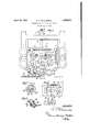
- Figure 1 is a front view of the device;
- Figure 2 is a front view of an alternative form of feeler;
- Figure 8 is a horizontal central section of Figure 2
- Figure 4 is a front view of an alternative form of feeler mounting.
- 1 is a framework carrying the device.
- a frame 2 is adapted to slide vertically in the framework 1 by'means of Vs 3 engaging V grooves in wheels 4 pivoted on the framework 1.
- the frame 2 is downwardly pressed by a weight 5, and its downward movement is limited by means of a rod 6 attached to the frame, and adjusting nuts 7 bearing on the framework 1.
- the feeler consists of a wheel 8 with rubber covering or tire 9, pivoted in a member 10.
- the diamond 11 is mounted in a holder '12 which is linked to the member 10 by a iever 13 pivoted to the frame-2 at 14, link 15 and lever '16, pivoted to the frame at 17 and to the member 10 at 18.
- the member '10 is adapted to slide in slots 19 in project'iOnsQO of the frame 2, having suflicient play in the slots 1-9 to take care of the arcuate movement of'the pivot 18.
- the link 15 has a length-adjusting nut or turnbuckle 24, and the holder 12 is adjustable in the lever 13 whereby the relative positions of feeler wheel 8 and diamond '11 may be adjusted.
- Wheels '25 are pivoted on projections '26 of the frame 2,. i
- a sheet of glass 27 is travelling from left to right, and, in the position shown, has passed under the left hand wheel -2'5, thereby raising the frame 2
- the forward edge of the glass 27 has just come into oontact wit-h the feeler wheel 8 and continued travel .of the glass will raise the wheel 8 thereby bringing the diamond 11 into contact with the glass at a point 28 slightly back of the forward edge of the glass.
- the depth of out made by the diamond is determined the length-adjusting nut 2 1.
- the piece 30 can turn in the member 10, so that the member is not lifted until the glass, in its continued movement, also raises the right-hand wheel 29
- the diamond therefore is not brought into contact with the glass until the right-hand wheel29 is raised; it is, however, brought out of contact with the glass as soon as the left-hand wheel 29 falls off the back edge of the glass.
- the position of the diamond relatively to the two wheels 29, 29, thevdiamond can be brought into contact with the glass at a point back of the front edge and brought out of contactwith the glass at a point in front of th back edge.
- FIG. 4 shows analternative device for attaining the same object as that attained by the device shown in Figures 2 and 3.
- the feeler member 10 slides, asin Figure 1, in slots in the projections 20, but" the slots are lengthened as at 19, 19, while a spring 32 normally retains the member 10, as shown, against one side of each slot.
- the forward edge of the glass presses the'feeler wheel 8 to the right, it first turns the member 10 counter-clockwise on its pivot 18 until it reaches the other sides of-the slot-s 19, and only then raises the feeler I wheel to bring the diamond into contact with the glass.
- the forward edge of the glass would then be in the position shown in dotted lines, before it began to raise the feeler wheel 8, and the diamond willthen be at the point 33 in order to come into contact with the glass at the point 28, which, at the time of contact, will be in advance of the centre line of the feeler wheel 8.
- the member 10 will be brought back into its normal position, in which it is shown in Figure 4, by the spring 32, and, when the back edge of the glass passes the centre line of the feeler wheel 8, the wheel, by falling, will raise the diamond as it reaches the back edge.
- Cutter holder devicerfor cutting travelling flat glass comprising a frame adapted to be raised by and reston the glass, a cutter pivoted to. the frame, a feeler pivoted to the frame and adapted to be raised relatively to r the frame by the glass and a connection be tween the feeler and the cutter adapted to bring the cutter into contact with the glass when the feeler is raised.
- ling flat glass comprising a frame adapted to be raised by and reston the glass, a cutter pivoted to the frame, a feeler pivoted to the frame and adapted to be raised relatively to the frame by the glass and a connection between the feeler and the cutter adapted to bring the cutter into contact with the glass behind its front edge when the feeler is raised and out of contact with the glass before its back edge when the feeler falls.
- Cutter holder device for cutting travelling flat glass comprising a frame adapted,
- a cutter pivoted to the frame, a feeler pivoted to the frame and adapted to be raised relatively to the frame by the glass, a covering on the feeler so soft that the glass appreciably beds itself therein before raising the feeler and a connect-ion between the feeler and the cutter adapted to bring the cutter into contact with the glass behind its front edge whenthe feeler is raised and out of contact with the glass before its back edge when the feeler falls.
- the feelerwheel will raise a little later and will fall a little sooner than if the wheel were of hard substance. 7
Landscapes
- Chemical & Material Sciences (AREA)
- Engineering & Computer Science (AREA)
- Materials Engineering (AREA)
- Organic Chemistry (AREA)
- Life Sciences & Earth Sciences (AREA)
- Mechanical Engineering (AREA)
- Wood Science & Technology (AREA)
- Forests & Forestry (AREA)
- Re-Forming, After-Treatment, Cutting And Transporting Of Glass Products (AREA)
Description
April 19, 1932. R. c. WILLIAMSON APPARATUS FOR CUTTING FLAT GLASS Filed Aug. 8, 1931 Patented Apr. 19, 1932 UNITED STATES PATENT OFFICE ROBERT cameras \VILLIAMSQN, or nonoesrnn, ENGLAND, Asslenon To rrnxmeron nnornnns shaman. or mvnnroor, ENGLAND, A LIMITED LrABILrrY oomrany APPARATUS FOR CUTTING FLAT GIASS Application filed August 8, 1931, Serial No. 556,018, and in Great tBritain August 11, 1930. I
This invention relates to apparatus for ,cutting flat glass and has for its object an improved device for applying the diamond or wheel to the glass.
In the following specification and claims it is assumed that a diamond is used as a cutter and that the glass is caused to travel beneath the diamond, but it is to be understood that the specification and claims are deemed to include the equivalent apparatus in which a wheel is ,used' as cutter and in which the diamond or wheel is caused to travel over stationary glass.
According to the invention a diamond holder and a feeler are so mounted on a frame that the upward movement of the feeler, when it is raised by the forward edge of the glass, causes a downward movement of the diamond hold- ,er to bring the diamond into contact with the glass at a point back of the front edge,
whereby the diamond is protected against in jury by being struck by the forward edge of the glass.
Further, the diamond may also be caused to rise from the glass before reaching the back end of the glass, either by a feeler having two points of contact with the glass, one in advance of the other, or by a feeler adapted to yield forwardly when struck by the forward edge of the glass, or by the use of yielding material, such as soft rubber, at the point of .contactbetween the forward edge of the glass and the feeler.
The frame carrying the diamond holder and feeler is provided with wheels .or the like adapted to rest on the glass, and is capable .of up and down movement and is downwardly pressed. By these means the relative ,position of feeler and diamond is independent of the thickness of the glass.
In the accompanying drawings Figure 1 is a front view of the device; Figure 2 is a front view of an alternative form of feeler;
Figure 8 is a horizontal central section of Figure 2, and
Figure 4 is a front view of an alternative form of feeler mounting.
Referring to Figure 1, 1 is a framework carrying the device. A frame 2 is adapted to slide vertically in the framework 1 by'means of Vs 3 engaging V grooves in wheels 4 pivoted on the framework 1. The frame 2 is downwardly pressed by a weight 5, and its downward movement is limited by means of a rod 6 attached to the frame, and adjusting nuts 7 bearing on the framework 1. 1
The feeler consists of a wheel 8 with rubber covering or tire 9, pivoted in a member 10. The diamond 11 is mounted in a holder '12 which is linked to the member 10 by a iever 13 pivoted to the frame-2 at 14, link 15 and lever '16, pivoted to the frame at 17 and to the member 10 at 18. The member '10 is adapted to slide in slots 19 in project'iOnsQO of the frame 2, having suflicient play in the slots 1-9 to take care of the arcuate movement of'the pivot 18.
A spring 21 between the lever 16 and a the spring 21 and serves to take up "backlash in the pivot-s of the linkage. The link 15 has a length-adjusting nut or turnbuckle 24, and the holder 12 is adjustable in the lever 13 whereby the relative positions of feeler wheel 8 and diamond '11 may be adjusted.
Wheels '25 are pivoted on projections '26 of the frame 2,. i
I A sheet of glass 27 is travelling from left to right, and, in the position shown, has passed under the left hand wheel -2'5, thereby raising the frame 2 The forward edge of the glass 27 has just come into oontact wit-h the feeler wheel 8 and continued travel .of the glass will raise the wheel 8 thereby bringing the diamond 11 into contact with the glass at a point 28 slightly back of the forward edge of the glass.
The depth of out made by the diamond is determined the length-adjusting nut 2 1.
Since the :position of the frame 2"is determined by the upper surface ;,o-f fthegl-ass on which the wheels 25 rest, the relative position of the feeler wheel 8 and-the-di amond 11 when operative os i t'ion is independent of the thickness of e glass. iln t'he alternative formof ifeelerishow n in 29 are pivoted on a double-crank piece 30 which is pivoted at 31 in the member 10. When the forward edge of the glass 27 raises the left-hand wheel 29, the piece 30 can turn in the member 10, so that the member is not lifted until the glass, in its continued movement, also raises the right-hand wheel 29 The diamond therefore is not brought into contact with the glass until the right-hand wheel29 is raised; it is, however, brought out of contact with the glass as soon as the left-hand wheel 29 falls off the back edge of the glass. By suitably adjusting, horizontally, the position of the diamond relatively to the two wheels 29, 29, thevdiamond can be brought into contact with the glass at a point back of the front edge and brought out of contactwith the glass at a point in front of th back edge.
- Figure 4 (in which the same reference figures indicate parts similar to those bearing the same references in Figure 1) shows analternative device for attaining the same object as that attained by the device shown in Figures 2 and 3. The feeler member 10 slides, asin Figure 1, in slots in the projections 20, but" the slots are lengthened as at 19, 19, while a spring 32 normally retains the member 10, as shown, against one side of each slot. When the forward edge of the glass presses the'feeler wheel 8 to the right, it first turns the member 10 counter-clockwise on its pivot 18 until it reaches the other sides of-the slot-s 19, and only then raises the feeler I wheel to bring the diamond into contact with the glass.
The forward edge of the glass would then be in the position shown in dotted lines, before it began to raise the feeler wheel 8, and the diamond willthen be at the point 33 in order to come into contact with the glass at the point 28, which, at the time of contact, will be in advance of the centre line of the feeler wheel 8. As soon as the feeler wheel 8 has been raised and runs on the surface of the glass, the member 10 will be brought back into its normal position, in which it is shown in Figure 4, by the spring 32, and, when the back edge of the glass passes the centre line of the feeler wheel 8, the wheel, by falling, will raise the diamond as it reaches the back edge.
Instead of mounting the feeler member 10 so as toyield as in the arrangement of Figure v4, the necessary yielding may take place at the surface of the feeler wheel itself, by
front edge of the glass if'the wheel covering 9 were hard, it will, if the covering 9 be soft, make contact with the glass back of the front edge and rise off the glass before the back edge.
Having described my invention, I declare that what I claim and desire to secure by Letters Patent is 1. Cutter holder devicerfor cutting travelling flat glass comprising a frame adapted to be raised by and reston the glass, a cutter pivoted to. the frame, a feeler pivoted to the frame and adapted to be raised relatively to r the frame by the glass and a connection be tween the feeler and the cutter adapted to bring the cutter into contact with the glass when the feeler is raised. I
2. Cutter holder device for cutting travel-.
ling flat glass comprising a frame adapted to be raised by and reston the glass,a cutter pivoted to the frame, a feeler pivoted to the frame and adapted to be raised relatively to the frame by the glass and a connection between the feeler and the cutter adapted to bring the cutter into contact with the glass behind its front edge when the feeler is raised and out of contact with the glass before its back edge when the feeler falls.
3. Cutter holder device for cutting travelling flat glass comprising a frame adapted,
to be raised by and rest on the glass, a cutter pivoted to the frame, a feeler pivoted to the frame and adapted to be raised relatively to the frame by the glass, a covering on the feeler so soft that the glass appreciably beds itself therein before raising the feeler and a connect-ion between the feeler and the cutter adapted to bring the cutter into contact with the glass behind its front edge whenthe feeler is raised and out of contact with the glass before its back edge when the feeler falls.
In witness whereof 'I'have affixed my sig: nature hereto. 7
ROBERT CHARLES WILLIAMSON.
forming its covering 9 of rubber soft enough 1 to be appreciably indented by the edgesof the glass. In consequence ofthis yielding,
the feelerwheel will raise a little later and will fall a little sooner than if the wheel were of hard substance. 7
If then, in the arrangement of Figure 1, the diamond be so adjusted that it would make contact with the upper angle of the
Applications Claiming Priority (1)
| Application Number | Priority Date | Filing Date | Title |
|---|---|---|---|
| GB23990/30A GB355928A (en) | 1930-08-11 | 1930-08-11 | Improvements in or relating to apparatus for cutting flat glass |
Publications (1)
| Publication Number | Publication Date |
|---|---|
| US1855078A true US1855078A (en) | 1932-04-19 |
Family
ID=10204620
Family Applications (1)
| Application Number | Title | Priority Date | Filing Date |
|---|---|---|---|
| US556018A Expired - Lifetime US1855078A (en) | 1930-08-11 | 1931-08-08 | Apparatus for cutting flat glass |
Country Status (5)
| Country | Link |
|---|---|
| US (1) | US1855078A (en) |
| DE (1) | DE577001C (en) |
| FR (1) | FR721140A (en) |
| GB (1) | GB355928A (en) |
| NL (1) | NL30864C (en) |
Cited By (5)
| Publication number | Priority date | Publication date | Assignee | Title |
|---|---|---|---|---|
| US2601725A (en) * | 1945-03-02 | 1952-07-01 | Union Des Verreries Mecaniques | Glass-cutting machine |
| US2705390A (en) * | 1952-11-14 | 1955-04-05 | Pilkington Brothers Ltd | Method of and apparatus for cutting a moving ribbon of glass |
| US2711617A (en) * | 1951-12-13 | 1955-06-28 | Hutting Sash & Door Company | Glass cutting devices |
| US3130499A (en) * | 1960-10-05 | 1964-04-28 | Pittsburgh Plate Glass Co | Glass cutting apparatus |
| US3230625A (en) * | 1961-11-17 | 1966-01-25 | Siemens Ag | Method and apparatus for scoring semiconductor plates to be broken into smaller bodies |
Families Citing this family (4)
| Publication number | Priority date | Publication date | Assignee | Title |
|---|---|---|---|---|
| DE1159141B (en) * | 1958-11-10 | 1963-12-12 | Saint Gobain | Device for cutting glass |
| DE1197198B (en) * | 1960-01-25 | 1965-07-22 | Conrad Lechmann | Glass cutter |
| US3276302A (en) * | 1963-04-15 | 1966-10-04 | Saint Gobain Corp | Glass cutter |
| US4411195A (en) * | 1982-01-12 | 1983-10-25 | Multidick Inc. | Printing press within tear-line tracing means |
-
1930
- 1930-08-11 GB GB23990/30A patent/GB355928A/en not_active Expired
-
1931
- 1931-08-07 NL NL57987A patent/NL30864C/en active
- 1931-08-07 FR FR721140D patent/FR721140A/en not_active Expired
- 1931-08-08 US US556018A patent/US1855078A/en not_active Expired - Lifetime
- 1931-08-08 DE DEP63652A patent/DE577001C/en not_active Expired
Cited By (5)
| Publication number | Priority date | Publication date | Assignee | Title |
|---|---|---|---|---|
| US2601725A (en) * | 1945-03-02 | 1952-07-01 | Union Des Verreries Mecaniques | Glass-cutting machine |
| US2711617A (en) * | 1951-12-13 | 1955-06-28 | Hutting Sash & Door Company | Glass cutting devices |
| US2705390A (en) * | 1952-11-14 | 1955-04-05 | Pilkington Brothers Ltd | Method of and apparatus for cutting a moving ribbon of glass |
| US3130499A (en) * | 1960-10-05 | 1964-04-28 | Pittsburgh Plate Glass Co | Glass cutting apparatus |
| US3230625A (en) * | 1961-11-17 | 1966-01-25 | Siemens Ag | Method and apparatus for scoring semiconductor plates to be broken into smaller bodies |
Also Published As
| Publication number | Publication date |
|---|---|
| DE577001C (en) | 1933-05-26 |
| GB355928A (en) | 1931-09-03 |
| NL30864C (en) | 1933-08-16 |
| FR721140A (en) | 1932-02-29 |
Similar Documents
| Publication | Publication Date | Title |
|---|---|---|
| US1855078A (en) | Apparatus for cutting flat glass | |
| ES253528U (en) | Seat having movable lumbar support. | |
| ES418094A1 (en) | Multi-function physical exercise apparatus | |
| GB930903A (en) | ||
| US2685327A (en) | Adjustable vehicle seat back | |
| US1676155A (en) | Circuit breaker and closer | |
| GB1238547A (en) | ||
| US2775780A (en) | Windshield wipers | |
| US2685764A (en) | Glass cutter | |
| ES340089A1 (en) | Mechanism for adjusting the backrest of seats in vehicles | |
| GB450249A (en) | Improvements relating to "on and off" castors for furniture | |
| GB744577A (en) | Improvements in adjustable seats | |
| US1761351A (en) | Holddown for squaring shears | |
| US2343681A (en) | Adjustable footrest | |
| GB387402A (en) | Novel or improved device for use in slicing or cutting comestibles | |
| US1821247A (en) | Adjustable seat | |
| US499801A (en) | Copy-holder | |
| US2147485A (en) | Ironing press | |
| US1519793A (en) | Pedal holder | |
| US2256162A (en) | Wringer and the like | |
| US1642328A (en) | Foot rest | |
| USD94461S (en) | Design for a bottle | |
| US1791895A (en) | Safety device for clothes wringers | |
| GB503766A (en) | Improvements relating to easy or occasional chairs | |
| US1921932A (en) | Chair |