US1855059A - Golf club shaft - Google Patents
Golf club shaft Download PDFInfo
- Publication number
- US1855059A US1855059A US561747A US56174731A US1855059A US 1855059 A US1855059 A US 1855059A US 561747 A US561747 A US 561747A US 56174731 A US56174731 A US 56174731A US 1855059 A US1855059 A US 1855059A
- Authority
- US
- United States
- Prior art keywords
- section
- shaft
- handle
- metallic
- sleeve
- Prior art date
- Legal status (The legal status is an assumption and is not a legal conclusion. Google has not performed a legal analysis and makes no representation as to the accuracy of the status listed.)
- Expired - Lifetime
Links
Images
Classifications
-
- A—HUMAN NECESSITIES
- A63—SPORTS; GAMES; AMUSEMENTS
- A63B—APPARATUS FOR PHYSICAL TRAINING, GYMNASTICS, SWIMMING, CLIMBING, OR FENCING; BALL GAMES; TRAINING EQUIPMENT
- A63B60/00—Details or accessories of golf clubs, bats, rackets or the like
-
- A—HUMAN NECESSITIES
- A63—SPORTS; GAMES; AMUSEMENTS
- A63B—APPARATUS FOR PHYSICAL TRAINING, GYMNASTICS, SWIMMING, CLIMBING, OR FENCING; BALL GAMES; TRAINING EQUIPMENT
- A63B60/00—Details or accessories of golf clubs, bats, rackets or the like
- A63B60/06—Handles
- A63B60/08—Handles characterised by the material
Definitions
- rIhis invention relates to improvements in golf clubs and particularly to golf club shafts.
- the present invention contemplates a composite golf shaft in that the shaft is formed of tubular metallic material throughout a major por- '20 tion of its length, while its handle section is of wood.
- a further object is to provide a satisfactory mode of attaching the wooden handle to a tubular metallic shaft body.
- a still further object is to reinforce the connection between the wooden handle and steel shaft proper.
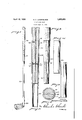
- Figure l is an elevational view of a golf club constructed in accordance with the present invention.
- Fig. 2 is a longitudinal sectional view through the wooden handle section and a portion of the tubular metallic section;
- Fig. 3 is an elevational view of the handle section removed from the shaft
- Fig. 4 is an elevational view of the connecting sleeve
- Fig. 5 is an elevational view of the end of the tubular metallic shaft to which the handle is attached.
- Fig. 6 is a transverse sectional view4 on line 6 6 of Fig. 2.
- the present invention -seeks to render it possible to utilize sections of tubularmetallc material which, under previous practices, would be too short for use in a golf club shaft.
- this is accomplished by having the major portion of ⁇ the shaft formed of a tubular metalic member to which is attached a Wooden handle section, the length of the two elements aggregating the desired club length.
- the wooden handle section the length of the two elements aggregating the desired club length.
- the shaft is composed primarily of the tubular metallic section 10 that extends the major portion of the length of the shaft and a wooden handle section l1.
- .section l0 is a tapering cross-section, the .wooden handle sect-ion being attached to its larger end and the club lhead l2 attached to itssmaller end.
- The'tubular metallic section 10 will varyin length in different clubs, depending upon thel length of the scrap material being utilized or upon the length that is desired inthe finished article.
- sleeve 14 is surrounded by a metallic sleeve 14 and this sleeve overlaps the larger end of the metallic section of the shaft.
- This sleeve, and that portion of the handle which is engaged thereby are also preferably of tapering cross-sec-A tion.
- sleeve 14 is provided on its interior with a shoulder 15 adapted to register with the end of the shaft section 10 when the parts are assembled and the handle section 11 is formed with a shoulder section 10 as to be covered 'or concealed by that portion ofthe sleeve 14 that overlaps section 10.
- the wooden handle section, the sleeve and a portion of section 10 are completely covered with the usual wrapping material 19 so that the finished article has the appearance'of an all steel shaft.
- the wooden handle 11 With the wooden handle 11 forming a driving lit in the section 10 and the shoulder 16 on said handle section abutting against the interior shoulder on sleeve 14 as well as against the upper end vof shaft section 10, and with the cross pins irmly securing the several parts together, an extreme- V ly rigid connection is obtained. It has been found that such a connection will withstand all the strains placed upon it. In this way there is obtained a shaft where the material that has heretofore been scrapped is utilized, and, as pointed out, the resulting product will have the same feel to the player as an all wood shaft.;
- a reinforce rod 20 may be provided, said rod extending longitudinally through tlie handle section 10. yIt is preferred that this .rod'extend from a ⁇ point beyond the upper end of sleeve 14 to the extremity of the handle section within the metallic section 10v although it may terminate somewhat short of this point so far as its strengthening properties are concerned.
- the sleeve 14 has beenshown and described as provided with ⁇ a shoulder 15, it will be understood that this shoulder is not absolutely necessary and may be dispensed with, the sleeve having ⁇ a plane uninterrupted tapering inner surface adapted to make a wedging fit on the handle and shaft'proper.
- Vha-t I claim is: -1.A-golf club shaftcomprising a tubular metallic section extending the ma] or portion of thelength of the shaft, a wooden handle section extending into said metallic section, a metal sleeve surrounding the point of junction of said sections, fastening elements ex.- tending through said metallic sectionv and said sleeve into said handle section, and a reinforce element extending longitudinally through said handle section.
- a golf club shaft comprising a tubulary metallic section, a wooden handle section secured in said tubular section, a tubular metallic sleeve overlapping the Apoint of Junction of said sections, means securing said sleeve to the handle section, a Ishoulder on'theinterior of said sleeve, and a' shoulder on said handle section abutting the end of the metallic section and the shoulder on the sleeve.
- a golf club shaft comprising .a'tubular 4.
- a golf club shaft comprising atubular .15j metallic section, a wooden handle'section secured in said metallic section,'a metallic sleeve secured to butcovering only a minor portion of the length of said wooden handle sect-ion, said sleeve overlapping the end off;
- a golf club shaft comprising a? tubular metallic section, a vwooden handle section securedin said metallic section, a metallic sleeve vattached to said wooden handle section and extending oversaid metallicsection, an in-V HERBERT o. LAGERBLADE; y
Landscapes
- Health & Medical Sciences (AREA)
- General Health & Medical Sciences (AREA)
- Physical Education & Sports Medicine (AREA)
- Golf Clubs (AREA)
Description
April 19, 1932. H Q LAGERBLADE v 1,855,059
GOLF CLUB SHAFT Filed Sept. 8, 1931 Patented Apr. 19, 1932 UNITED STATES HERBERT C. LAGERBLADE, OE BRISTOL, CONNECTICUT GOLF CLUB SHAFT Application led September 8, 1,931. SeriaLNo. 561,747.
rIhis invention relates to improvements in golf clubs and particularly to golf club shafts.
During the course of a year, manufacturers of tubular golf shafts will accumulate thousands of pieces of steel shafts that are perfectly good except that they are too short for use as a golf shaft. Heretofore all of this material has been scrapped. This scrap material quite frequently runs as high as twentyfive inches in length. VThis is due to the fact that very often there is a slight imperfection in the steel that will cause a break in the shaft toward the upper end while the lower end is perfectly good and of high quality.
In order to eliminate this waste, the present invention contemplates a composite golf shaft in that the shaft is formed of tubular metallic material throughout a major por- '20 tion of its length, while its handle section is of wood.
A further object is to provide a satisfactory mode of attaching the wooden handle to a tubular metallic shaft body.
A still further object is to reinforce the connection between the wooden handle and steel shaft proper.
With these and other objects in view the invention consists in certain details of construction and combinations and arrangements of parts all as will hereinafter be more fully described and the novel features thereof particularly pointed out in the appended claims.
In the accompanying drawings:
Figure l is an elevational view of a golf club constructed in accordance with the present invention; f
Fig. 2 is a longitudinal sectional view through the wooden handle section and a portion of the tubular metallic section;
Fig. 3 is an elevational view of the handle section removed from the shaft;
Fig. 4 is an elevational view of the connecting sleeve;
Fig. 5 is an elevational view of the end of the tubular metallic shaft to which the handle is attached, and
Fig. 6 is a transverse sectional view4 on line 6 6 of Fig. 2.
"w As stated, the present invention-seeks to render it possible to utilize sections of tubularmetallc material which, under previous practices, would be too short for use in a golf club shaft. Generally stated, this is accomplished by having the major portion of `the shaft formed of a tubular metalic member to which is attached a Wooden handle section, the length of the two elements aggregating the desired club length. Not only does such an arrangement permit the use of otherwise 3E scrap material but the provision of the woodenhandle lends to the nished club a feel, different from that of a club having a metallic handle portion. That is, many players do not like the feel of a steelshaft under the grip portion of the club, claiming that it is too hard while others claim that they receive a shock when hitting a ball with the club, due to the steel shaft. In a composite shaft such as now proposed the woodenhandle section imparts to the shaft the desired feel, and, in addition, any shock `such as complained of is also eliminated. This is believed to be due to the fact that the wooden` handle section has certain torsioning properties.
In carrying out the invention the shaft is composed primarily of the tubular metallic section 10 that extends the major portion of the length of the shaft and a wooden handle section l1. Preferably, .section l0 is a tapering cross-section, the .wooden handle sect-ion being attached to its larger end and the club lhead l2 attached to itssmaller end. The'tubular metallic section 10 will varyin length in different clubs, depending upon thel length of the scrap material being utilized or upon the length that is desired inthe finished article.
It has been a difcult matter to provide a "i joint between a metallic section and a wooden section in a golf club that will have the desired strength to withstand the strains placed upon it when the club is in use. These difficulties are overcome in the present instance T by having the wooden handle section l1 formed with a tenon 13, `preferablytapered .and wedged in the large end lof the :metallic section 10.. Immediately beyond the larger end of :the metallic section endthe handle 11 l l ui Y Y handle.
is surrounded by a metallic sleeve 14 and this sleeve overlaps the larger end of the metallic section of the shaft. This sleeve, and that portion of the handle which is engaged thereby are also preferably of tapering cross-sec-A tion. To lend rigidity to the joint, sleeve 14 is provided on its interior with a shoulder 15 adapted to register with the end of the shaft section 10 when the parts are assembled and the handle section 11 is formed with a shoulder section 10 as to be covered 'or concealed by that portion ofthe sleeve 14 that overlaps section 10. After assembly of the parts as described, the wooden handle section, the sleeve and a portion of section 10 are completely covered with the usual wrapping material 19 so that the finished article has the appearance'of an all steel shaft. With the wooden handle 11 forming a driving lit in the section 10 and the shoulder 16 on said handle section abutting against the interior shoulder on sleeve 14 as well as against the upper end vof shaft section 10, and with the cross pins irmly securing the several parts together, an extreme- V ly rigid connection is obtained. It has been found that such a connection will withstand all the strains placed upon it. In this way there is obtained a shaft where the material that has heretofore been scrapped is utilized, and, as pointed out, the resulting product will have the same feel to the player as an all wood shaft.;
To further reinforce the connection a reinforce rod 20 may be provided, said rod extending longitudinally through tlie handle section 10. yIt is preferred that this .rod'extend from a` point beyond the upper end of sleeve 14 to the extremity of the handle section within the metallic section 10v although it may terminate somewhat short of this point so far as its strengthening properties are concerned.
It isV also desirable to protect the wood handle section against changes in weather-conditions. For this reasonV a sealing compound may be applied to the wood handle before it is driven into the metallic section 10. There are numerous cements and sealing waxes which will accomplish this purpose. Preferably, the entirewood handle is weatherproof as farl as possible, the connection heretofore described between the wooden section' and metallic section might also be supplemented by the use of solder between the overlapping portions of sleeve 14 and section 10.
While the sleeve 14 has beenshown and described as provided with `a shoulder 15, it will be understood that this shoulder is not absolutely necessary and may be dispensed with, the sleeve having `a plane uninterrupted tapering inner surface adapted to make a wedging fit on the handle and shaft'proper.
Vha-t I claim is: -1.A-golf club shaftcomprising a tubular metallic section extending the ma] or portion of thelength of the shaft, a wooden handle section extending into said metallic section, a metal sleeve surrounding the point of junction of said sections, fastening elements ex.- tending through said metallic sectionv and said sleeve into said handle section, and a reinforce element extending longitudinally through said handle section.`
2. A golf club shaft comprising a tubulary metallic section, a wooden handle section secured in said tubular section, a tubular metallic sleeve overlapping the Apoint of Junction of said sections, means securing said sleeve to the handle section, a Ishoulder on'theinterior of said sleeve, and a' shoulder on said handle section abutting the end of the metallic section and the shoulder on the sleeve.
3. A golf club shaft comprising .a'tubular 4. A golf club shaft comprising atubular .15j metallic section, a wooden handle'section secured in said metallic section,'a metallic sleeve secured to butcovering only a minor portion of the length of said wooden handle sect-ion, said sleeve overlapping the end off;
said metallic shaft section, and a wrapping covering the wooden handle sectionand said sleeve.
5. A golf club shaft comprising a? tubular metallic section, a vwooden handle section securedin said metallic section, a metallic sleeve vattached to said wooden handle section and extending oversaid metallicsection, an in-V HERBERT o. LAGERBLADE; y
ilo
Priority Applications (1)
| Application Number | Priority Date | Filing Date | Title |
|---|---|---|---|
| US561747A US1855059A (en) | 1931-09-08 | 1931-09-08 | Golf club shaft |
Applications Claiming Priority (1)
| Application Number | Priority Date | Filing Date | Title |
|---|---|---|---|
| US561747A US1855059A (en) | 1931-09-08 | 1931-09-08 | Golf club shaft |
Publications (1)
| Publication Number | Publication Date |
|---|---|
| US1855059A true US1855059A (en) | 1932-04-19 |
Family
ID=24243272
Family Applications (1)
| Application Number | Title | Priority Date | Filing Date |
|---|---|---|---|
| US561747A Expired - Lifetime US1855059A (en) | 1931-09-08 | 1931-09-08 | Golf club shaft |
Country Status (1)
| Country | Link |
|---|---|
| US (1) | US1855059A (en) |
-
1931
- 1931-09-08 US US561747A patent/US1855059A/en not_active Expired - Lifetime
Similar Documents
| Publication | Publication Date | Title |
|---|---|---|
| US1677099A (en) | Golf club | |
| US3819181A (en) | Hosel-less wood type golf club | |
| US3176987A (en) | Golf club including means for aligning the shaft, hosel and striking face | |
| US1611858A (en) | Baseball bat | |
| US3692306A (en) | Golf club having integrally formed face and sole plate with weight means | |
| US1569295A (en) | Golf-club head | |
| US3519271A (en) | Shaft and club head attaching means | |
| US1787415A (en) | Golf club | |
| US3810621A (en) | Hosel-less wood type golf club | |
| US5275409A (en) | Putter | |
| US2361415A (en) | Golf club | |
| US1620118A (en) | Golf club | |
| US1601770A (en) | Golf club | |
| US3410558A (en) | Golf club head attaching means | |
| US1585294A (en) | Golf club | |
| US2117129A (en) | Shaft for golf clubs and the like | |
| US1855059A (en) | Golf club shaft | |
| US5439218A (en) | Golf club hosel construction | |
| US2879065A (en) | Adjustable golf club | |
| US2007976A (en) | Golf club joint | |
| KR102835264B1 (en) | Park Golf Head's Crown Coupling Device | |
| US1781116A (en) | Shaft for golf clubs and the like | |
| US1564208A (en) | Golf club | |
| GB427717A (en) | Improvements relating to shafts for golf glubs | |
| DE202011000674U1 (en) | Golf clubs with a detachable screw connection between club head and club shaft |