US1855049A - Line tightener - Google Patents
Line tightener Download PDFInfo
- Publication number
- US1855049A US1855049A US551339A US55133931A US1855049A US 1855049 A US1855049 A US 1855049A US 551339 A US551339 A US 551339A US 55133931 A US55133931 A US 55133931A US 1855049 A US1855049 A US 1855049A
- Authority
- US
- United States
- Prior art keywords
- handle
- line
- hooks
- members
- slack
- Prior art date
- Legal status (The legal status is an assumption and is not a legal conclusion. Google has not performed a legal analysis and makes no representation as to the accuracy of the status listed.)
- Expired - Lifetime
Links
- 238000010276 construction Methods 0.000 description 2
- 210000003813 thumb Anatomy 0.000 description 2
- 238000003466 welding Methods 0.000 description 2
- 101100452003 Caenorhabditis elegans ape-1 gene Proteins 0.000 description 1
- 238000005452 bending Methods 0.000 description 1
- 238000006073 displacement reaction Methods 0.000 description 1
- 210000003811 finger Anatomy 0.000 description 1
- 238000004519 manufacturing process Methods 0.000 description 1
Images

Classifications
-
- D—TEXTILES; PAPER
- D06—TREATMENT OF TEXTILES OR THE LIKE; LAUNDERING; FLEXIBLE MATERIALS NOT OTHERWISE PROVIDED FOR
- D06F—LAUNDERING, DRYING, IRONING, PRESSING OR FOLDING TEXTILE ARTICLES
- D06F53/00—Clothes-lines; Supports therefor
-
- Y—GENERAL TAGGING OF NEW TECHNOLOGICAL DEVELOPMENTS; GENERAL TAGGING OF CROSS-SECTIONAL TECHNOLOGIES SPANNING OVER SEVERAL SECTIONS OF THE IPC; TECHNICAL SUBJECTS COVERED BY FORMER USPC CROSS-REFERENCE ART COLLECTIONS [XRACs] AND DIGESTS
- Y10—TECHNICAL SUBJECTS COVERED BY FORMER USPC
- Y10T—TECHNICAL SUBJECTS COVERED BY FORMER US CLASSIFICATION
- Y10T24/00—Buckles, buttons, clasps, etc.
- Y10T24/39—Cord and rope holders
- Y10T24/3916—One-piece
- Y10T24/392—Wire
-
- Y—GENERAL TAGGING OF NEW TECHNOLOGICAL DEVELOPMENTS; GENERAL TAGGING OF CROSS-SECTIONAL TECHNOLOGIES SPANNING OVER SEVERAL SECTIONS OF THE IPC; TECHNICAL SUBJECTS COVERED BY FORMER USPC CROSS-REFERENCE ART COLLECTIONS [XRACs] AND DIGESTS
- Y10—TECHNICAL SUBJECTS COVERED BY FORMER USPC
- Y10T—TECHNICAL SUBJECTS COVERED BY FORMER US CLASSIFICATION
- Y10T24/00—Buckles, buttons, clasps, etc.
- Y10T24/39—Cord and rope holders
- Y10T24/3984—Alignable aperture and spring pressed moving element
Definitions
- This invention relates to linetighteners of the kind adapted for taking up slack at an intermediate point in a clothesline or any other line supported at its ends.
- One of the objects of our invention is to provide an improved line tightener of this kind particularly in respect to the shape and location of a pair of line engaging-hooks at one end of a handle, which hooks function in combination with one or more slack take-up hooks in such manner as to facilitate application of the line tightener to a line.
- f-Another object of our invention is to improve the manufacture of a line tightener oft his kindby utilizing comparatively heavy wire shaped in novel ways to provide a structure having the characteristics of our invention.
- Still another object is to provide a Wire tight-ener of the character described which may be produced economically and will be strong and durable for the purposes intended.
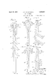
- Figures 1, 2 and 3 show one species of our inventionf Figure 1 showing the line tightenerin perspective, and Figs. 2 and 3 being front and side views, respectively, on an enlarged scale;
- Figs. 4 and 5 are front and side views, respectively,oianother species of our invention.
- the line tightener is made up entirely of a single piece of comparativelyheavy wire.
- Thispiece oi wire is shaped toprovide a series of line engaging elements 8 in parallel spaced relation at one side of a handle member 9 of the wire.
- Each'element 8 is-formed, asshown, by bending the wireback upon itself and'these elements are hei-d'in'spa-ced relation by the intermediate connecting portions 11 which are disposed in alignment with the handle member i).
- the line engaging elements 8 arefdisposed in angular relation to the handle member-' 9 so that each serves, in efie'ct, as a hook over which to engage and hold .a slack portion of a line, 'aswill be presently described.
- the main strip of wire is bent up on -itselt at to provide a handle member 13 in spaced 7 parallel relation with the handlemem ber andcrossing the elements Sintermediate't'heir ends.
- Said elements 8 are each welded to the handle member 13, thus uniting the spaced handle members'into a rigidstnue-' ture.
- the terminal end portions of-the wine are shaped to provide, line engaginglhooks 14c and 15 disposed in rigid, laterally spaced relation at opposite sides of :a' center "major axis of the handle designated by 1 6 Fig,
- these engaging hooks 14 and 15 are disposed in f substantially parallel relation with saidsmajor axis 16 and are arranged so as tozzrbe open at the end opposite fromthe hand grasp end of the handle, the latter obviouslyibeing thelower end of the handle shown in Figure 1.
- the end portions Of thQ'WlIE) members are crossed at 17 and are again crossed at 18,
- the hook 1? would then be engaged beneath the line, the handle would be swung to the left sufficiently to engage one of the elements 8 (depending on the amount ofslack to be taken up) over the line, and the handle would then be iii) swung back to the right about the book 14 as a fulcrum sufficiently to engage the hook 15 beneath the opposite stretch of the line, and,
- the handle when so engaged, the handle is released and allowed to drop to, the upright position shownin Figure 1, or in case the resistance set up by the line is too great the handle is used as a'lever and is forcibly swung to the upright position.
- the line is securely engaged by the hooks 14 so that there is no chance ofthe line slipping'oft' of these hooks.
- thehooks 14 and 15 may be engaged with the line by an easy manipulation of the handle and'with the'use of merely the one hand grasping the handle.
- Figs. 4 and 5 we have shown another species of ourinvention in which the heavy wire body member is bent upon itself to pro vide two closed ends with the terminal ends 19 located at any suitable point and being united by welding; I-Iere, two spaced parallel handle members 21 and 22 are united and reenforced by cross-members 23 which projec't beyond oneof the handle'membersand provide line engaging take-up elements similar to the elements 8.
- the combined handle reenforcing and line take-up elements-23 are each welded to the handle members 21 and 22, respectively.
- Suitable line engaging hooks may be provided at the end of the handle to serve thesame purpose as the hooks 14 and 15.
- our invention contemplates twisting the end portion'24 at right angles to the plane of the handle members 21.-22 and welding to this end portion 24 a cross-member 25, the terminal portions of which are. shaped to provide hooks 26 and 27 similar to the hooks Hand 15.
- Figs. 6 and 7 we have shown still another species of our invention in which a single wire is bent upon itself to provide spaced parallel handle members 28 and 29, the terminal ends. of which are shaped to provide hooks 31 and 32 similar to the hooks 14 and 15 above described.
- an ape1 tured spacing member 33 is slipped over the ends of the wire before the bend 34 is made and the latter is brought around sufliciently to clamp the member 33 in position and hold it against displacement.
- a slack takeup hook 35 slidably mounted on the handle members 28 and 29 so that it is capable of being moved to any position throughout the length of said handle or throughout any given portion thereof for the purpose of taking up a variable amountof slack and for permitting quick adjustment of slack from one position to another.
- the hook element proper is fixed to a crosshead 36 having openings to receive the handle members.
- This crosshead 36 is normally loose on the handle members and may be freely slid lengthwise thereon, but when the hook end 35 thereof is engaged by a line under tension it will be canted into binding engagement with the handle members and thus locked in position on the handle.
- the operation ofapplying this species of our line tightener to a line is the same as in the previous cases except, however, that adjustments of slack take up may be more quickly effected by proper manipulation of the adjustable take-up hook 35- 36.
- This hook may be slid upwardly on the handle by means of the thumb of the hand grasping the handle or it may be slid downwardly by means of the index finger of the same hand acting against the crosshead 36.
- adjustment of this take-up hook may be effected in any suitable manner as the matter of making an adjustment of this kind with the constructionprovided would be simple and apparent to the average per- It will be manifest from the foregoing that our invention contemplates the pro: vision of a novel line tightener capable of embodiment in different forms, of which three species are here shown, and that changes may be made in details of construction without departing from the spirit and scope of the invention as expressed in the appended claims.
- a line tightener comprising a handle of comparatively heavy wire bent to provide spaced handle members terminating at one end in laterally spaced hooks in rigid relative relation, and line engaging means on the handle for taking up a variable length of a slack portion of a line engaged over said laterally spaced hooks.
- a line tightener of the character described comprising a-' handle provided at one end with a pair of line engaging hooks in fixed, laterally spaced relation opening toward said end so as to receive a line brought over the hooks from said end, said hooks being fixed with respect to the handle, and line engaging means on the handle for holding an intermediate portion of the line at any of different distances from the hooks whereby to take up slack in the line.
- a line tightener comprising a handle of comparatively heavy wire bent to provide spaced handle members terminating at one end in laterally spaced hooks in rigid relative relation, one of said members being bent intermediate its ends to provide a series of line engaging hooks spaced longitudinally of the handle.
- a line tightener of the character described comprising a handle formed of a single piece of comparatively heavy wire bent upon itself to provide two spaced handle members in substantially parallel relation, the terminal end of each handle member being bent to provide a hook disposed in a plane laterally offset from the center major axis of the handle and substantially parallel therewith and opening toward the adjacent end of the handle to receive a line brought into the hook recess from said end of the handle and to permit disposal of a slack portion of the line intermediate the spaced hooks, and means on the handle for engaging and holding said slack portion, of the line at any of different distances from said hooks whereby to take up variable slack in the line.
- a line tightener of the character described comprising a handle formed of wire bent upon itself to provide spaced handle members, a Wire member medially Welded to the handle adjacent to and extending crosswise of one end thereof, the terminal ends of said wire member being bent to provide line engaging hooks, and means on the handle for engaging and holding different lengths of slack line intermediate the said hooks.
- a line tightener of the character described comprising a handle formed of wire bent upon itself to provide spaced handle members, laterally spaced line engaging hooks fixed on the handle at one end thereof, and a series of wire members welded onto the spaced handle members in substantially parallel relation and spaced apart longitu dinally of said handle members and projecting beyond the handle at the side thereof common to the first mentioned hooks, said projecting members providing line engaging elements for holding slack line.
- a line tightener of the character described comprising a handle formed of wire bent upon itself to provide spaced handle members, a pair of fixed, laterally spaced line engaging hooks rigid on the handle at one end thereof, and a slack take-up hook mounted to slide lengthwise upon the handle members and adapted to lock in any of a number of different positions thereon to take up different lengths of slack of line engaged over said hooks.
- a line tighter comprising spaced longitudinal members forming a handle and reenforced by a series of cross-members projecting beyond the handle andserving as line engaging elements, and a pair of line engaging elements fixed on one end of the handle in laterally spaced relation at opposite sides of the center major axis of the handle.
- a line tightener comprising an elongated handle, a slack take-up hook mounted on the handle with capacity for adjustment longitudinally thereon, and a pair of line engaging elements fixed on one end of the handle and spaced apart laterally at opposite sides of the center major axis of the handle.
Landscapes
- Engineering & Computer Science (AREA)
- Textile Engineering (AREA)
- Wire Processing (AREA)
Description
April 19, 1932. I B. c. HARVEY ET AL 1,855,049
LINE TIGHTENER Filed July 20, 1931 2 Sheets-Sheet l April 19, 1932. B. c HARVEY ET AL 1,855,049
LINE TIGHTENER Filed July 20, 1951 2 Sheets-Sheet 2 /JJ Z i \V J6 u 36 k: s 35 E I I l 29 1 ,1 L ::'::I is
k L W *q m "a Patented Apr. 19, 1932 UNITED STATES BER-HEARD G. HABVEY.AND JOHN A. SHEEN, QF'ROGKFORDJILIJNOIS V p LINE TIGHTENER Application filed. July 20, 193.1. ,Serial No. 551,339.
This invention relates to linetighteners of the kind adapted for taking up slack at an intermediate point in a clothesline or any other line supported at its ends.
One of the objects of our invention is to provide an improved line tightener of this kind particularly in respect to the shape and location of a pair of line engaging-hooks at one end of a handle, which hooks function in combination with one or more slack take-up hooks in such manner as to facilitate application of the line tightener to a line.
f-Another object of our invention is to improve the manufacture of a line tightener oft his kindby utilizing comparatively heavy wire shaped in novel ways to provide a structure having the characteristics of our invention.
Still another object is to provide a Wire tight-ener of the character described which may be produced economically and will be strong and durable for the purposes intended.
We have also aimed to provide more than one species of our-invention, the details of which are described hereinafter.
' Referring to the -drawings 1 Figures 1, 2 and 3 show one species of our inventionfFigure 1 showing the line tightenerin perspective, and Figs. 2 and 3 being front and side views, respectively, on an enlarged scale;
Figs. 4 and 5 are front and side views, respectively,oianother species of our invention, and
@Figs'fi and 7- show front and side views, respectively, of still another species of our invention.
In the 'form of our invention shown. in Figures 1, 2 and 3 the line tightener is made up entirely of a single piece of comparativelyheavy wire. "Thispiece oi wire is shaped toprovide a series of line engaging elements 8 in parallel spaced relation at one side of a handle member 9 of the wire. Each'element 8 is-formed, asshown, by bending the wireback upon itself and'these elements are hei-d'in'spa-ced relation by the intermediate connecting portions 11 which are disposed in alignment with the handle member i). The line engaging elements 8 arefdisposed in angular relation to the handle member-' 9 so that each serves, in efie'ct, as a hook over which to engage and hold .a slack portion of a line, 'aswill be presently described. 'The main strip of wire is bent up on -itselt at to provide a handle member 13 in spaced 7 parallel relation with the handlemem ber andcrossing the elements Sintermediate't'heir ends. Said elements 8 are each welded to the handle member 13, thus uniting the spaced handle members'into a rigidstnue-' ture. The terminal end portions of-the wine are shaped to provide, line engaginglhooks 14c and 15 disposed in rigid, laterally spaced relation at opposite sides of :a' center "major axis of the handle designated by 1 6 Fig,
2. According to our invention these engaging hooks 14 and 15 are disposed in f substantially parallel relation with saidsmajor axis 16 and are arranged so as tozzrbe open at the end opposite fromthe hand grasp end of the handle, the latter obviouslyibeing thelower end of the handle shown in Figure 1. In the species of our invention here shown the end portions Of thQ'WlIE) members are crossed at 17 and are again crossed at 18,
in the latter instance these end portions being shaped to describe substantially 180, as shown in Fig. 2, and being disposed substan tially in .a common plane at right angles to the plane of the handle members 19 and-13. The crossed portions 18 are united bywelding, thus holding the hook members 14 and 15 in rigid spaced relation aswell' as rigid with respect to the handleprope-rQ Our improved line tightener may easily manipulated with one hand, for application to a line, such for example as aclothes'line, for the purposeofta-king up slack at apoint intermediate theends which are attached to supporting structures. in such case, the handle would be grasped, say, in the right hand, withthe thumb uppermost, that is, toward the'double hook end. The hook 1?: would then be engaged beneath the line, the handle would be swung to the left sufficiently to engage one of the elements 8 (depending on the amount ofslack to be taken up) over the line, and the handle would then be iii) swung back to the right about the book 14 as a fulcrum sufficiently to engage the hook 15 beneath the opposite stretch of the line, and,
when so engaged, the handle is released and allowed to drop to, the upright position shownin Figure 1, or in case the resistance set up by the line is too great the handle is used as a'lever and is forcibly swung to the upright position. It will be manifest that with this construction the line is securely engaged by the hooks 14 so that there is no chance ofthe line slipping'oft' of these hooks. Furthermore, by arranging thehooks 14 and 15 in this manner they may be engaged with the line by an easy manipulation of the handle and'with the'use of merely the one hand grasping the handle. It will also be manifest that in'case sufficient slack is not taken up by engaging the line over the first hook element S-the handle maybe swung to the right to disengage the line from the hook 15 and to permit engagement of the line over the next hook element 8 or whichever of these to be taken up, whereupon the handle is again manipulated to engage the hook 15. In the latter operation it will be noted that in case the:line.offers any considerable resistance in 5 taking-up the; final slack, as for example wherealine is loaded with clothes. the handle is'used as alever andis swung on the fulcrum 14 downwardly in a clockwise direction viewing Figure 1, to the upright position therein shown.
- In Figs. 4 and 5 we have shown another species of ourinvention in which the heavy wire body member is bent upon itself to pro vide two closed ends with the terminal ends 19 located at any suitable point and being united by welding; I-Iere, two spaced parallel handle members 21 and 22 are united and reenforced by cross-members 23 which projec't beyond oneof the handle'membersand provide line engaging take-up elements similar to the elements 8. In this case, the combined handle reenforcing and line take-up elements-23 are each welded to the handle members 21 and 22, respectively. Suitable line engaging hooks may be provided at the end of the handle to serve thesame purpose as the hooks 14 and 15. In this connection our invention contemplates twisting the end portion'24 at right angles to the plane of the handle members 21.-22 and welding to this end portion 24 a cross-member 25, the terminal portions of which are. shaped to provide hooks 26 and 27 similar to the hooks Hand 15.
In Figs. 6 and 7 we have shown still another species of our invention in which a single wire is bent upon itself to provide spaced parallel handle members 28 and 29, the terminal ends. of which are shaped to provide hooks 31 and 32 similar to the hooks 14 and 15 above described. In this case, an ape1 tured spacing member 33 is slipped over the ends of the wire before the bend 34 is made and the latter is brought around sufliciently to clamp the member 33 in position and hold it against displacement. In this form of our invention We prefer to employ a slack takeup hook 35 slidably mounted on the handle members 28 and 29 so that it is capable of being moved to any position throughout the length of said handle or throughout any given portion thereof for the purpose of taking up a variable amountof slack and for permitting quick adjustment of slack from one position to another. The hook element proper is fixed to a crosshead 36 having openings to receive the handle members. This crosshead 36 is normally loose on the handle members and may be freely slid lengthwise thereon, but when the hook end 35 thereof is engaged by a line under tension it will be canted into binding engagement with the handle members and thus locked in position on the handle. The operation ofapplying this species of our line tightener to a line is the same as in the previous cases except, however, that adjustments of slack take up may be more quickly effected by proper manipulation of the adjustable take-up hook 35- 36.
This hook may be slid upwardly on the handle by means of the thumb of the hand grasping the handle or it may be slid downwardly by means of the index finger of the same hand acting against the crosshead 36. However, adjustment of this take-up hook may be effected in any suitable manner as the matter of making an adjustment of this kind with the constructionprovided would be simple and apparent to the average per- It will be manifest from the foregoing that our invention contemplates the pro: vision of a novel line tightener capable of embodiment in different forms, of which three species are here shown, and that changes may be made in details of construction without departing from the spirit and scope of the invention as expressed in the appended claims.
We claim: 7
l. A line tightener comprising a handle of comparatively heavy wire bent to provide spaced handle members terminating at one end in laterally spaced hooks in rigid relative relation, and line engaging means on the handle for taking up a variable length of a slack portion of a line engaged over said laterally spaced hooks.
2. A line tightener of the character described comprising a-' handle provided at one end with a pair of line engaging hooks in fixed, laterally spaced relation opening toward said end so as to receive a line brought over the hooks from said end, said hooks being fixed with respect to the handle, and line engaging means on the handle for holding an intermediate portion of the line at any of different distances from the hooks whereby to take up slack in the line.
3. A line tightener comprising a handle of comparatively heavy wire bent to provide spaced handle members terminating at one end in laterally spaced hooks in rigid relative relation, one of said members being bent intermediate its ends to provide a series of line engaging hooks spaced longitudinally of the handle.
4. A line tightener of the character described comprising a handle formed of a single piece of comparatively heavy wire bent upon itself to provide two spaced handle members in substantially parallel relation, the terminal end of each handle member being bent to provide a hook disposed in a plane laterally offset from the center major axis of the handle and substantially parallel therewith and opening toward the adjacent end of the handle to receive a line brought into the hook recess from said end of the handle and to permit disposal of a slack portion of the line intermediate the spaced hooks, and means on the handle for engaging and holding said slack portion, of the line at any of different distances from said hooks whereby to take up variable slack in the line.
5. A line tightener of the character described comprising a handle formed of wire bent upon itself to provide spaced handle members, a Wire member medially Welded to the handle adjacent to and extending crosswise of one end thereof, the terminal ends of said wire member being bent to provide line engaging hooks, and means on the handle for engaging and holding different lengths of slack line intermediate the said hooks.
6. A line tightener of the character described comprising a handle formed of wire bent upon itself to provide spaced handle members, laterally spaced line engaging hooks fixed on the handle at one end thereof, and a series of wire members welded onto the spaced handle members in substantially parallel relation and spaced apart longitu dinally of said handle members and projecting beyond the handle at the side thereof common to the first mentioned hooks, said projecting members providing line engaging elements for holding slack line.
7. A line tightener of the character described comprising a handle formed of wire bent upon itself to provide spaced handle members, a pair of fixed, laterally spaced line engaging hooks rigid on the handle at one end thereof, and a slack take-up hook mounted to slide lengthwise upon the handle members and adapted to lock in any of a number of different positions thereon to take up different lengths of slack of line engaged over said hooks.
8. A line tighter comprising spaced longitudinal members forming a handle and reenforced by a series of cross-members projecting beyond the handle andserving as line engaging elements, and a pair of line engaging elements fixed on one end of the handle in laterally spaced relation at opposite sides of the center major axis of the handle.
9. A line tightener comprising an elongated handle, a slack take-up hook mounted on the handle with capacity for adjustment longitudinally thereon, and a pair of line engaging elements fixed on one end of the handle and spaced apart laterally at opposite sides of the center major axis of the handle.
In witness whereof we have hereunto affixed our signatures.
BERNHARD C. HARVEY. JOHN A. SHEEN.
Priority Applications (1)
| Application Number | Priority Date | Filing Date | Title |
|---|---|---|---|
| US551339A US1855049A (en) | 1931-07-20 | 1931-07-20 | Line tightener |
Applications Claiming Priority (1)
| Application Number | Priority Date | Filing Date | Title |
|---|---|---|---|
| US551339A US1855049A (en) | 1931-07-20 | 1931-07-20 | Line tightener |
Publications (1)
| Publication Number | Publication Date |
|---|---|
| US1855049A true US1855049A (en) | 1932-04-19 |
Family
ID=24200865
Family Applications (1)
| Application Number | Title | Priority Date | Filing Date |
|---|---|---|---|
| US551339A Expired - Lifetime US1855049A (en) | 1931-07-20 | 1931-07-20 | Line tightener |
Country Status (1)
| Country | Link |
|---|---|
| US (1) | US1855049A (en) |
Cited By (2)
| Publication number | Priority date | Publication date | Assignee | Title |
|---|---|---|---|---|
| US8544784B2 (en) | 2010-10-08 | 2013-10-01 | Cargazen, Inc. | Line tightening device |
| US20140332648A1 (en) * | 2013-05-07 | 2014-11-13 | Cynthia J. Hasbany | Jewelry holder |
-
1931
- 1931-07-20 US US551339A patent/US1855049A/en not_active Expired - Lifetime
Cited By (3)
| Publication number | Priority date | Publication date | Assignee | Title |
|---|---|---|---|---|
| US8544784B2 (en) | 2010-10-08 | 2013-10-01 | Cargazen, Inc. | Line tightening device |
| US20140332648A1 (en) * | 2013-05-07 | 2014-11-13 | Cynthia J. Hasbany | Jewelry holder |
| US9408479B2 (en) * | 2013-05-07 | 2016-08-09 | Cynthia J. Hasbany | Jewelry holder |
Similar Documents
| Publication | Publication Date | Title |
|---|---|---|
| US920313A (en) | Wire basket. | |
| US1855049A (en) | Line tightener | |
| US439994A (en) | Opening-instrument for binding-clips | |
| US2758622A (en) | Adjustable nut and lobster cracker | |
| US2512818A (en) | Fishhook extractor | |
| US1006584A (en) | Binder. | |
| US670894A (en) | Comb. | |
| US2086317A (en) | Wire stretching tool | |
| US973034A (en) | Wire-fence stretcher. | |
| DE392014C (en) | Band-like, electric heater to be folded around vessels u. like | |
| US1422660A (en) | Loop-forming terminal clamp | |
| US1551914A (en) | Four-way-one-way strap buckle | |
| US1659602A (en) | Wire stretcher | |
| US1774120A (en) | Hair waver and method | |
| US1164146A (en) | Wire-stretcher. | |
| US868094A (en) | Fork. | |
| US1321598A (en) | Clay m | |
| US1180666A (en) | Wire-stretcher. | |
| US1048098A (en) | Binding device. | |
| US1081344A (en) | Handle for kerosene-tins and the like. | |
| US1322655A (en) | Clothes pin ob clamp | |
| US1725172A (en) | Capsule forceps | |
| US1499959A (en) | Plate lifter | |
| US2844058A (en) | Apparatus for bending tubes | |
| US1342625A (en) | Wire-stretcher |