US1854904A - Rod weeder - Google Patents
Rod weeder Download PDFInfo
- Publication number
- US1854904A US1854904A US543603A US54360331A US1854904A US 1854904 A US1854904 A US 1854904A US 543603 A US543603 A US 543603A US 54360331 A US54360331 A US 54360331A US 1854904 A US1854904 A US 1854904A
- Authority
- US
- United States
- Prior art keywords
- frame
- rod
- main
- weeder
- pivoted
- Prior art date
- Legal status (The legal status is an assumption and is not a legal conclusion. Google has not performed a legal analysis and makes no representation as to the accuracy of the status listed.)
- Expired - Lifetime
Links
Images

Classifications
-
- A—HUMAN NECESSITIES
- A01—AGRICULTURE; FORESTRY; ANIMAL HUSBANDRY; HUNTING; TRAPPING; FISHING
- A01B—SOIL WORKING IN AGRICULTURE OR FORESTRY; PARTS, DETAILS, OR ACCESSORIES OF AGRICULTURAL MACHINES OR IMPLEMENTS, IN GENERAL
- A01B39/00—Machines specially adapted for working soil on which crops are growing
- A01B39/12—Machines specially adapted for working soil on which crops are growing for special purposes, e.g. for special culture
- A01B39/18—Machines specially adapted for working soil on which crops are growing for special purposes, e.g. for special culture for weeding
- A01B39/19—Rod weeders, i.e. weeder with rotary rods propelled beneath the soil surface
Definitions
- This invention relates to improvements in the construction of tillage implements such as rotary rod weeders.
- the main object of the invention is to provide a frame construction which will embody means permitting the implement carrying frame to yield or swing when the implement, as for instance the rotary rod of a rod weeder, encounters an obstruction and restores it to normal position automatically when the rod has been carried over it.
- Another object is to provide a self restoring, releasable coupling for normally looking together certain movable and stationary elements of the frame structure.
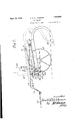
- Figure 1 is a side elevation of a rod weeder embodying the invention
- Figure 2 is a plan view of the same
- FIG 3 is an enlarged detail view of the adjusting and latch mechanism, as viewed on the line 8-3, Figure 2;
- Figure 4 is an enlarged detail view of the front ends of the frame members carrying the latch device, shown in assembled position in Figure 1.
- the invention has been illustrated as embodied in a rod weeder having a laterally extended main frame 10 supported on end wheels 11, the aXis of which is located intermediate the front and rear sides of the frame 10, and preferably forward of the central transverse line of the frame.
- the frame 10 has secured to it a plurality of downwardly curved standards 12, in the lower ends of which the usual ground engaging rotary rod 13 is journaled.
- This rod may be driven from one of the wheels by a sprocket chain 14.
- an auxiliary frame or member 15 shown in the present instance as comprising a pair of parallel angle bars pivoted at their rear ends to a bolt 16 extending transversely through upstanding brackets 17 at the rear of frame 10.
- the twin bars of the supplemental frame extend to the forward side of frame 10 where they are connected by an upstandin inverted U-shaped yoke 18 ( Figure 3- tlr'rough a pivot bolt 19.
- One of the two bars composing the auxiliary frame 15 has secured to it a laterally extending bracket piece 20 carrying parallel forwardly projecting lugs 21, between which there is journaled a latch roller 22.
- the front bar of frame '10 is provided with depending lugs 23, between which there is pivoted an upright latch member or dog'24, the upper end of which is formed with a cam face 25 leading to a rounded notch 26, formed to engage the roller 22.
- the do 24 is normally pressed towards the roller by a coil spring 27 carried on .
- a retaining rod 28 projecting forwardly from the front member of the frame 10 through a suitable aperture in the dog 24.
- the overbalancing weight of the rear end of frame 10 will cause the front sides of the frames 10 and 15 to again come together and be automatically relocked in normal position as the cam face 25 of dog 24 rides over roller 22 and it seats in notch 26.
- the frames above described are connected to a draft frame which preferably extends above them and which comprises a main central draft member 29, which is preferably pivoted to the main and auxiliary frames 10 and 11 on the same bolt 16 which pivotally connects those frames together.
- the main draft member 29 has diagonal brace members which are respectively pivoted to the rear side of the frame 10 in transverse axial alignment with the bolt- 16, as shown in Figure 2.
- the main draft member 29 extends forwardly between the arms of we the yoke 18 and is provided at its forward 4:.
- end with depending hitch bars 31, which are the overload release coupling comprises a adapted for connection to a draw bar of a sprlng pressed dog pivoted on one of the tractor, shown at 32.
- a rod weeder comprising a horizontally disposed main frame rockably supported on axially aligned end wheels located between its front and rear sides, a ground engaging rotary rod carried by the frame back of said wheels, an auxiliary frame extending fore and aft of the main frame and pivoted thereto on a transverse axis located back of the axis of said wheels, a forwardly extending draft member pivoted to the rear end of the auxiliary frame on a transverse axis, and a vertically adjustable connection between the draft member and the forward end of the auxiliary frame.
- a rod weeder comprising a horizontally disposed main frame rockably supported on axially aligned end wheels located between its front and rear sides, a ground engaging rotary rod carried by the frame back of said wheels, an auxiliary frame pivoted to the rear side of the main frame on a transverse axis and extending to the front side thereof, an overload release coupling connecting the front side of said frames, and a forwardly extending draft member connected to the auxiliary frame.
Landscapes
- Life Sciences & Earth Sciences (AREA)
- Engineering & Computer Science (AREA)
- Mechanical Engineering (AREA)
- Soil Sciences (AREA)
- Environmental Sciences (AREA)
- Soil Working Implements (AREA)
Description
April 19, 1932. A. E. w. JOHNSON ROD WEEDER Filed June 11, 1951 2 Sheets-Sheet l April 1932- A. E. w. JOHNSON 1,854,904
ROD WEEDER Filed June 11, 1951 2 Sheets-Sheet 2 n M n 17H m1 n firnOQZZZZzfi/OWM y M 21 V 2a Patented Apr. 19, 1932 UNITED 3mm FATENT OFFICE ARNOLD E. W. JOHNSON, OF CHICAGO, ILLINOIS, ASSIGNOR TO INTER-NATIONAL HARVESTER COMPANY, A CORPORATION OF NEW JERSEY :aon WEEDER Application filed June 11,
This invention relates to improvements in the construction of tillage implements such as rotary rod weeders.
The main object of the invention is to provide a frame construction which will embody means permitting the implement carrying frame to yield or swing when the implement, as for instance the rotary rod of a rod weeder, encounters an obstruction and restores it to normal position automatically when the rod has been carried over it.
Another object is to provide a self restoring, releasable coupling for normally looking together certain movable and stationary elements of the frame structure.
The foregoing and other objects and ad vantages are obtained by the construction hereinafter more particularly defined and claimed, and illustrated in the accompanying drawings, where:
Figure 1 is a side elevation of a rod weeder embodying the invention;
Figure 2 is a plan view of the same;
Figure 3 is an enlarged detail view of the adjusting and latch mechanism, as viewed on the line 8-3, Figure 2; and
Figure 4 is an enlarged detail view of the front ends of the frame members carrying the latch device, shown in assembled position in Figure 1.
In the present instance the invention has been illustrated as embodied in a rod weeder having a laterally extended main frame 10 supported on end wheels 11, the aXis of which is located intermediate the front and rear sides of the frame 10, and preferably forward of the central transverse line of the frame. The frame 10 has secured to it a plurality of downwardly curved standards 12, in the lower ends of which the usual ground engaging rotary rod 13 is journaled. This rod may be driven from one of the wheels by a sprocket chain 14. Centrally of the main frame 10 there is provided an auxiliary frame or member 15, shown in the present instance as comprising a pair of parallel angle bars pivoted at their rear ends to a bolt 16 extending transversely through upstanding brackets 17 at the rear of frame 10. The twin bars of the supplemental frame extend to the forward side of frame 10 where they are connected by an upstandin inverted U-shaped yoke 18 (Figure 3- tlr'rough a pivot bolt 19. One of the two bars composing the auxiliary frame 15, has secured to it a laterally extending bracket piece 20 carrying parallel forwardly projecting lugs 21, between which there is journaled a latch roller 22. Immediately below a roller 22 the front bar of frame '10 is provided with depending lugs 23, between which there is pivoted an upright latch member or dog'24, the upper end of which is formed with a cam face 25 leading to a rounded notch 26, formed to engage the roller 22. The do 24 is normally pressed towards the roller by a coil spring 27 carried on .a retaining rod 28 projecting forwardly from the front member of the frame 10 through a suitable aperture in the dog 24. With this construction the main and auxiliary frames will normally be locked together in the position shown in full lines on Figure 1 but any abnormal strain applied to the rod 13 tending to force the rear portion of framelO upwardly will overcome the pressure of the spring 27, causing the latch device to release and permit the frames to swing to the dotted line positions of Figure 1.
After the obstruction has been passed the overbalancing weight of the rear end of frame 10 will cause the front sides of the frames 10 and 15 to again come together and be automatically relocked in normal position as the cam face 25 of dog 24 rides over roller 22 and it seats in notch 26.
The frames above described are connected to a draft frame which preferably extends above them and which comprises a main central draft member 29, which is preferably pivoted to the main and auxiliary frames 10 and 11 on the same bolt 16 which pivotally connects those frames together. The main draft member 29 has diagonal brace members which are respectively pivoted to the rear side of the frame 10 in transverse axial alignment with the bolt- 16, as shown in Figure 2. The main draft member 29 extends forwardly between the arms of we the yoke 18 and is provided at its forward 4:. The combination of claim 2, in which end with depending hitch bars 31, which are the overload release coupling comprises a adapted for connection to a draw bar of a sprlng pressed dog pivoted on one of the tractor, shown at 32.
frames and a complemental latch piece se- In order that the rod carrying frame may cured on the other frame.
be adjusted to raise and lower the rotary rod vertically the draft member 29, at the point where it passes through the yoke 18, has secured to it a bearing piece 33, in which there is swiveled an upright adjusting shaft 34, which passes through a thread aperture in the upper end of the yoke member 18, has a crank handle 35 at its upper end. The shaft 34 is threaded where it passes through the yoke 18 and its rotation by means of the crank handle 35, will cause the auxiliary frame 15 and with it the main frame 10, to be rocked on the axis of the supporting wheels 11 and on the pivot 16, to adjust the position of the rotary rod.
With the construction above described, it will be seen that provision has been made for any desired adjustment of the rod carrying frame and that, independently of such adjustment, the rod carrying frame will be released and allowed to swing when an obstruction is encountered, and will automatically be relocked in normal position when the obstruction is passed. The preferred construction illustrated is obviously susceptible of modification without departure from the scope of the invention as defined in the following claims.
What is claimed is:
1. A rod weeder comprising a horizontally disposed main frame rockably supported on axially aligned end wheels located between its front and rear sides, a ground engaging rotary rod carried by the frame back of said wheels, an auxiliary frame extending fore and aft of the main frame and pivoted thereto on a transverse axis located back of the axis of said wheels, a forwardly extending draft member pivoted to the rear end of the auxiliary frame on a transverse axis, and a vertically adjustable connection between the draft member and the forward end of the auxiliary frame.
2. A rod weeder comprising a horizontally disposed main frame rockably supported on axially aligned end wheels located between its front and rear sides, a ground engaging rotary rod carried by the frame back of said wheels, an auxiliary frame pivoted to the rear side of the main frame on a transverse axis and extending to the front side thereof, an overload release coupling connecting the front side of said frames, and a forwardly extending draft member connected to the auxiliary frame.
3. The combination of claim 2, in which the draft member is pivotally connected to the auxiliary frame at the rear on a transverse axis and connected thereto by a vertically adjustable connection at the front.
In testimony whereof I aflix my signature.
ARNOLD E. W. JOHNSON.
Priority Applications (1)
| Application Number | Priority Date | Filing Date | Title |
|---|---|---|---|
| US543603A US1854904A (en) | 1931-06-11 | 1931-06-11 | Rod weeder |
Applications Claiming Priority (1)
| Application Number | Priority Date | Filing Date | Title |
|---|---|---|---|
| US543603A US1854904A (en) | 1931-06-11 | 1931-06-11 | Rod weeder |
Publications (1)
| Publication Number | Publication Date |
|---|---|
| US1854904A true US1854904A (en) | 1932-04-19 |
Family
ID=24168733
Family Applications (1)
| Application Number | Title | Priority Date | Filing Date |
|---|---|---|---|
| US543603A Expired - Lifetime US1854904A (en) | 1931-06-11 | 1931-06-11 | Rod weeder |
Country Status (1)
| Country | Link |
|---|---|
| US (1) | US1854904A (en) |
Cited By (3)
| Publication number | Priority date | Publication date | Assignee | Title |
|---|---|---|---|---|
| US3274712A (en) * | 1964-04-16 | 1966-09-27 | Earthcavator Company Inc | Retractable scarifier |
| US3274713A (en) * | 1964-04-16 | 1966-09-27 | Earthcavator Company Inc | Hydraulically controlled scarifier |
| US4605072A (en) * | 1982-04-20 | 1986-08-12 | Fred A. Jones | Soil cultivating apparatus |
-
1931
- 1931-06-11 US US543603A patent/US1854904A/en not_active Expired - Lifetime
Cited By (3)
| Publication number | Priority date | Publication date | Assignee | Title |
|---|---|---|---|---|
| US3274712A (en) * | 1964-04-16 | 1966-09-27 | Earthcavator Company Inc | Retractable scarifier |
| US3274713A (en) * | 1964-04-16 | 1966-09-27 | Earthcavator Company Inc | Hydraulically controlled scarifier |
| US4605072A (en) * | 1982-04-20 | 1986-08-12 | Fred A. Jones | Soil cultivating apparatus |
Similar Documents
| Publication | Publication Date | Title |
|---|---|---|
| US1854904A (en) | Rod weeder | |
| US2746770A (en) | Laterally flexible draft mechanism | |
| US1663249A (en) | Tractor cultivator | |
| US1596838A (en) | Harrow attachment for plows | |
| US2922480A (en) | Adjustable device for mounting for agricultural implements | |
| US3337242A (en) | Hitch structure for agricultural implements | |
| US2609647A (en) | Tractor mounted disk harrow | |
| US2264783A (en) | Disk harrow | |
| US2552307A (en) | Disk harrow | |
| US1580145A (en) | Harrow | |
| US598820A (en) | sharp | |
| US1854903A (en) | Rod weeder | |
| US2407094A (en) | Agricultural implement | |
| US2955664A (en) | Lift type convertible disk harrow | |
| US1260497A (en) | Disk harrow. | |
| US1436391A (en) | Draft means for tandem disk harrows | |
| US2614377A (en) | Disk harrow angling arm | |
| US1769123A (en) | Tractor disk harrow | |
| US1435161A (en) | Riding attachment | |
| US2604745A (en) | Disk harrow frame | |
| US1443364A (en) | Multiple-gang harrow | |
| US1504373A (en) | Rocking colter | |
| US1452184A (en) | Clod crusher | |
| US1832027A (en) | Tractor disk harrow | |
| US1941306A (en) | Farm implement |