US1854897A - Method of making bearing rings - Google Patents
Method of making bearing rings Download PDFInfo
- Publication number
- US1854897A US1854897A US416471A US41647129A US1854897A US 1854897 A US1854897 A US 1854897A US 416471 A US416471 A US 416471A US 41647129 A US41647129 A US 41647129A US 1854897 A US1854897 A US 1854897A
- Authority
- US
- United States
- Prior art keywords
- tool
- cutting
- bar
- trepanning
- races
- Prior art date
- Legal status (The legal status is an assumption and is not a legal conclusion. Google has not performed a legal analysis and makes no representation as to the accuracy of the status listed.)
- Expired - Lifetime
Links
- 238000004519 manufacturing process Methods 0.000 title description 10
- 238000000034 method Methods 0.000 description 18
- 239000000463 material Substances 0.000 description 8
- 239000002184 metal Substances 0.000 description 4
- 238000010276 construction Methods 0.000 description 2
- BNPVNZIUVMQZPU-DKIMLUQUSA-N Asn-Met-Trp-Asn Chemical compound C1=CC=C2C(C[C@H](NC(=O)[C@@H](NC(=O)[C@@H](N)CC(N)=O)CCSC)C(=O)N[C@@H](CC(N)=O)C(O)=O)=CNC2=C1 BNPVNZIUVMQZPU-DKIMLUQUSA-N 0.000 description 1
- 229910000831 Steel Inorganic materials 0.000 description 1
- 238000012986 modification Methods 0.000 description 1
- 230000004048 modification Effects 0.000 description 1
- 239000010959 steel Substances 0.000 description 1
Images
Classifications
-
- F—MECHANICAL ENGINEERING; LIGHTING; HEATING; WEAPONS; BLASTING
- F16—ENGINEERING ELEMENTS AND UNITS; GENERAL MEASURES FOR PRODUCING AND MAINTAINING EFFECTIVE FUNCTIONING OF MACHINES OR INSTALLATIONS; THERMAL INSULATION IN GENERAL
- F16C—SHAFTS; FLEXIBLE SHAFTS; ELEMENTS OR CRANKSHAFT MECHANISMS; ROTARY BODIES OTHER THAN GEARING ELEMENTS; BEARINGS
- F16C33/00—Parts of bearings; Special methods for making bearings or parts thereof
- F16C33/30—Parts of ball or roller bearings
- F16C33/58—Raceways; Race rings
- F16C33/64—Special methods of manufacture
-
- F—MECHANICAL ENGINEERING; LIGHTING; HEATING; WEAPONS; BLASTING
- F16—ENGINEERING ELEMENTS AND UNITS; GENERAL MEASURES FOR PRODUCING AND MAINTAINING EFFECTIVE FUNCTIONING OF MACHINES OR INSTALLATIONS; THERMAL INSULATION IN GENERAL
- F16C—SHAFTS; FLEXIBLE SHAFTS; ELEMENTS OR CRANKSHAFT MECHANISMS; ROTARY BODIES OTHER THAN GEARING ELEMENTS; BEARINGS
- F16C19/00—Bearings with rolling contact, for exclusively rotary movement
- F16C19/22—Bearings with rolling contact, for exclusively rotary movement with bearing rollers essentially of the same size in one or more circular rows, e.g. needle bearings
- F16C19/34—Bearings with rolling contact, for exclusively rotary movement with bearing rollers essentially of the same size in one or more circular rows, e.g. needle bearings for both radial and axial load
- F16C19/36—Bearings with rolling contact, for exclusively rotary movement with bearing rollers essentially of the same size in one or more circular rows, e.g. needle bearings for both radial and axial load with a single row of rollers
- F16C19/364—Bearings with rolling contact, for exclusively rotary movement with bearing rollers essentially of the same size in one or more circular rows, e.g. needle bearings for both radial and axial load with a single row of rollers with tapered rollers, i.e. rollers having essentially the shape of a truncated cone
-
- F—MECHANICAL ENGINEERING; LIGHTING; HEATING; WEAPONS; BLASTING
- F16—ENGINEERING ELEMENTS AND UNITS; GENERAL MEASURES FOR PRODUCING AND MAINTAINING EFFECTIVE FUNCTIONING OF MACHINES OR INSTALLATIONS; THERMAL INSULATION IN GENERAL
- F16C—SHAFTS; FLEXIBLE SHAFTS; ELEMENTS OR CRANKSHAFT MECHANISMS; ROTARY BODIES OTHER THAN GEARING ELEMENTS; BEARINGS
- F16C2300/00—Application independent of particular apparatuses
- F16C2300/02—General use or purpose, i.e. no use, purpose, special adaptation or modification indicated or a wide variety of uses mentioned
-
- Y—GENERAL TAGGING OF NEW TECHNOLOGICAL DEVELOPMENTS; GENERAL TAGGING OF CROSS-SECTIONAL TECHNOLOGIES SPANNING OVER SEVERAL SECTIONS OF THE IPC; TECHNICAL SUBJECTS COVERED BY FORMER USPC CROSS-REFERENCE ART COLLECTIONS [XRACs] AND DIGESTS
- Y10—TECHNICAL SUBJECTS COVERED BY FORMER USPC
- Y10T—TECHNICAL SUBJECTS COVERED BY FORMER US CLASSIFICATION
- Y10T29/00—Metal working
- Y10T29/49—Method of mechanical manufacture
- Y10T29/49636—Process for making bearing or component thereof
- Y10T29/49643—Rotary bearing
- Y10T29/49679—Anti-friction bearing or component thereof
- Y10T29/49689—Race making
Definitions
- This invention relates to a method of producing rings, and refers particularly to a novel method of producing rings which are used as inner and outer races of anti-friction roller bearings.
- the inner periphery of the outer race and the outer periphery of the inner race are tapered or beveled in the same general direction, for the reception between them of a plurality of rollers which may themselves be slightly beveled or cylindrical, as desired.
- these two rings or races are cut from a single piece of metal, in the same relationship to each other as that in which they are subsequently assembled for use.
- the arrangement is such, however, that there is very little clearance for the cutting tool and for the chips, and other complications arise due to the fact that the cutting tool cannot be given a straight line movement ina direction parallel to the common axes of the rings.
- the invention consists in the novel method set forth in the fol-,
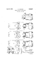
- Figure 1 is a transverse sectional vie through the inner and outer races of an antifriction bearing of one type to be produced by the present invention
- Fig. 2 is a similar view of the bearing 5 races in the relation in which they are produced, the outer race' being reversed endwise from the position in which it is ultimately as-.
- Fig. 3 is a fragmentary diagrammatic view, partly in cross section, illustrating the first According to the present invention, the
- Fig. 4 is a view similar toFig. 3, illustrating the next step in the method
- Fig. 5 is a similar view, showing how the outer ring is separated from the inner ring stock
- Fig. 6 is another similar view, showing how the inner ring is finally severed from the bar stock from which it is produced.
- Fig. 7 is a detail end view of one of the trepanning tools used in the novel method.
- rings for anti-friction bearings which as shown in Fig. 1, comprise an inner ring or race 10 and-an outer ring or race 11.
- the inner ring 10 has a tapered outer periphery 12, and the outer ring 11 has a tapered inner periphery 13, which together constitute raceways for the reception between them of a plurality of rollers, as is well known to those skilled in the art.
- These tapered raceways 12 and 13 extend in the same general direction, although they need not necessarily have the same degree of taper.
- the inner race 10 is thicker or longer than the outer race 11, and is provided at the end of its greater diameter with a flange 14, and it has a central bore 15 extending through it to provide for the fitting of the ring upon a shaft. 7
- the rings 10 and 11 are assembled together for use in the relative positions shown in Fig. 1, but in accordance with the present invention they are simultaneously produced from a single piece of metal in the relation ship shown in Fig. 2.
- the end of largest diameter of the raceway 13 is at the same end of the stock as the end of smallest diameter of the raceway 12, so that the tapers of said raceways extend in opposite directions instead of in the same general direction.
- a rotatable chuck 17 with one end of the bar extending sufiiciently from the end of the chuck to allow of operation upon the bar by suitable tools.
- the chuck 17 may be that of any desired type of machine well known in the art, for example, a lathe or mill, and the spindle may be arranged either vertically or horizontally, as desired.
- a cutting tool 18 is moved laterally inward against one side of the bar 16 as the same rotates, forming an annular groove 19, outwardly of which is what may be termed, a flange portion 20 of a thickness equal to that desired in the outer race or ring 11.
- Another tool 21 is moved axially against the rotating end of the bar 16, and is provided with a central boring member 22, which operates to form the central bore 15" in the end of the bar, and a pair of trepanning cutters 23, which are preferably arranged at diametrically opposite sides of the boring member 22 and spaced slightly therefrom.
- the tool 21 may operate upon the end of the bar 16 either at the same time as the cutter 18, or after said cutter has per formed its operation.
- the trepanning cutters 23 are each provided with a sharp cutting end 24 and with inner and outer cutting edges 25 and 26, which are angularly formed respectively to the same degree of taper as the raceways 12 and 13, when the latter are in the relationship shown in Fig. 2.
- the trepanning cutters 23 do not cut so deeply as the boring member 22, although, of course, if desired, they can be designed to perform the complete operation. I prefer, however, to use a series of trepanning tools, successively, for the purpose of providing greater clearance for the chips which are cut out ofthe rod by said tools. Therefore, in the preferred and illustrated steps of the method, the trepanning cutters 23 act upon the end of the bar 16 to cut a circular groove 27, and the tool 21 will be controlled by a cam or other suitable mechanism, so as to limit the inward feed of the tool.
- Another tool 21 is then employed to further the operations commenced by the tool 21, this tool 21 being of a construction similar to the tool 21, and including a central boring member 22 and trepanning cutters 23, as shown in Fig. 4.
- the ends 24: of the trepanning cutters 23 are adapted to cut more deeply into the bottom of the circular groove 27, and preferably said cutting ends 24 are of slightly less width than the ends 24 of the tool 21, so that in this intermediate step of the method, all of the cutting will be done by the ends 24 and by the adjacent portions of the tapered inner edges 25
- a tool 21 similar to 21 and 21 is employed, it having a central boring member 22 and trepanning cutters 23", which are adapted to out still
- the cutting ends 243 of the trepanning cutters 23 are narrower than those of either of the trepanning cutters 23 or 23*, whereas the outer sides 26 of said cutters are of the same dimensions and same degree of angularity as the cutting edges 26 of the first tool.
- the circular groove 27 is out entirely through the previously formed flange portion 20 and extends slightly beyond the inner side of said flange portion, so as to form a shoulder 28 upon the remaining tapered end 10* of the rod 16.
- the trepanning cutters 23 complete their cutting action through the flange portion 20, they sever the outer ring 11 from the remainder of the stock, and as the tool 21 is retracted from the end of the rotating stock, said outer ring 11 will remain upon said tool, as shownin Fig. 5.
- a cutting off tool 29 is then moved lateral- 1y against the rotating stock to cut off the inner ring or race 10 at a point inwardly from the shoulder 28 previously referred to.
- Said cutting off tool 29 is preferably thinner or narrower than the grooving tool 18, and engages the material at the base of the groove 19 which was first formed by said tool 18, leaving the small flange 14 at the end of largest diameter of the ring member 10.
- the tools 21, 21 and 21 may be arranged upon a slide to facilitate their successive presentation to the end of the rotating bar 16, or they may be mounted upon a turret, if that type of machine is to be employed.
- the tapered raceways 12 and 13 of the respective ring members 10 and 11 may be simultaneously formed by a tool of simple construction which moves axially with reference to the rotating stock 16 and chuck 17. Furthermore, it will be evident that by cutting the outer ring member 11 in a reversed endwise'relation to theinner ring member 10, greater clearance is provided for the trepanning cutters and for the metal chips which result from this operation. This greater clearance can be best appreciated by a comparison of Figs. 1 and 2, noting particularly the relative directions of the tapered raceways 12 and 13 in each of these figures.
- the separate ring members 10 and 11 may then be individually finished in a grinding machine or the like, as is customary, after which they can be assembled together for use in their ultimate relation, as shown in Fig. 1, in which relation the outer ring or race 11 is in a reversed endwise position with reference to that in which it was originally formed with the inner ring or race 10.
- Steps in the method of producing hearing races consist in providing a piece of material of suitable size, presenting one end of said material to a trepanning tool, and operating upon it to sever it into two concentric annular races having their respective raceways tapered in opposite directions.
- Steps in the method of producing bearing races consist in forming a substantially cylindrical piece of material with an annular flange on one end, and severing the same into two concentric races by cutting an annular groove endwise through said flange.
- Steps in the method of producing bearing races consist in forming a substantially cylindrical piece of material with an annular flange on one end, and severing the same into two concentric races by cutting an annular groove endwise through said flange, said annular groove being characterized by inner and outer peripheries which are respectively tapered in opposite directions.
- the method of producing inner and outer bearing races simultaneously which consists in forming a flange on one end of a metal bar, operating upon said flanged end of the bar with a tool to form an annular groove through the flange and thereby to sever an outer annular member from the bar, and subsequently severing an inner annular member from the bar, the outer annular member so formed being in a reversed endwise relation to that in which itwill subsequently be assembled for use with the inner annular member.
Landscapes
- Engineering & Computer Science (AREA)
- General Engineering & Computer Science (AREA)
- Mechanical Engineering (AREA)
- Manufacturing & Machinery (AREA)
- Rolling Contact Bearings (AREA)
Description
' J. A. GANSTER METHOD OF MAKING BEARING RINGS Filed Dec. 26,
April 19, 1932.
INVENTOR. 4. M
, 74m 1PM ATTORNEY-5.
N MWN NMWN Patented Apr. 19, 1932 PATENT OFFICE JOSEPH A. GANSTER, OF PHILADELPHIA, PENNSYLVANIA METHOD OF MAKING BEARING RINGS Application filed December 26, 1929. Serial No. 416,471.
This invention relates to a method of producing rings, and refers particularly to a novel method of producing rings which are used as inner and outer races of anti-friction roller bearings.
In bearings of the type to the manufacture of which this invention is particularly adapted, the inner periphery of the outer race and the outer periphery of the inner race are tapered or beveled in the same general direction, for the reception between them of a plurality of rollers which may themselves be slightly beveled or cylindrical, as desired. According to one prior art method of manu- 5 facture, these two rings or races are cut from a single piece of metal, in the same relationship to each other as that in which they are subsequently assembled for use. The arrangement is such, however, that there is very little clearance for the cutting tool and for the chips, and other complications arise due to the fact that the cutting tool cannot be given a straight line movement ina direction parallel to the common axes of the rings.
ring are cut simultaneously in a relatively reversed endwise relation, resulting in great simplication of the manufacturing steps, with greater accuracy and uniformity in. theprodnot. and at lower cost.
With the foregoing and other advantages and objects in view, the invention consists in the novel method set forth in the fol-,
lowing description, shown by way of illustration in the accompanying drawings, and specifically pointed out in the appended claims. In the drawings attached hereto, Figure 1 is a transverse sectional vie through the inner and outer races of an antifriction bearing of one type to be produced by the present invention; Fig. 2 is a similar view of the bearing 5 races in the relation in which they are produced, the outer race' being reversed endwise from the position in which it is ultimately as-. sembled with the inner race foractual use; Fig. 3 is a fragmentary diagrammatic view, partly in cross section, illustrating the first According to the present invention, the
step in the method of producing the rings of Figs. 1 and 2; I
Fig. 4 is a view similar toFig. 3, illustrating the next step in the method;
Fig. 5 is a similar view, showing how the outer ring is separated from the inner ring stock; r
Fig. 6 is another similar view, showing how the inner ring is finally severed from the bar stock from which it is produced; and
Fig. 7 is a detail end view of one of the trepanning tools used in the novel method.
While the invention is not restricted to such use, it is particularly adapted for the manufacture of rings for anti-friction bearings, which as shown in Fig. 1, comprise an inner ring or race 10 and-an outer ring or race 11. The inner ring 10 has a tapered outer periphery 12, and the outer ring 11 has a tapered inner periphery 13, which together constitute raceways for the reception between them of a plurality of rollers, as is well known to those skilled in the art. These tapered raceways 12 and 13 extend in the same general direction, although they need not necessarily have the same degree of taper. It is also to be noticed that the inner race 10 is thicker or longer than the outer race 11, and is provided at the end of its greater diameter with a flange 14, and it has a central bore 15 extending through it to provide for the fitting of the ring upon a shaft. 7
The rings 10 and 11 are assembled together for use in the relative positions shown in Fig. 1, but in accordance with the present invention they are simultaneously produced from a single piece of metal in the relation ship shown in Fig. 2. In other words, as
they are produced in accordance with the present invention, the end of largest diameter of the raceway 13 is at the same end of the stock as the end of smallest diameter of the raceway 12, so that the tapers of said raceways extend in opposite directions instead of in the same general direction. The advantages of this arrangement will be more apparent from the following description of the manufacturing steps.
As shown in Fig. 3, a bar 16 of steel or more deeply into the end of the rod.
other suitable material is secured in a rotatable chuck 17 with one end of the bar extending sufiiciently from the end of the chuck to allow of operation upon the bar by suitable tools. The chuck 17 may be that of any desired type of machine well known in the art, for example, a lathe or mill, and the spindle may be arranged either vertically or horizontally, as desired. A cutting tool 18 is moved laterally inward against one side of the bar 16 as the same rotates, forming an annular groove 19, outwardly of which is what may be termed, a flange portion 20 of a thickness equal to that desired in the outer race or ring 11. Another tool 21 is moved axially against the rotating end of the bar 16, and is provided with a central boring member 22, which operates to form the central bore 15" in the end of the bar, and a pair of trepanning cutters 23, which are preferably arranged at diametrically opposite sides of the boring member 22 and spaced slightly therefrom. The tool 21 may operate upon the end of the bar 16 either at the same time as the cutter 18, or after said cutter has per formed its operation. The trepanning cutters 23 are each provided with a sharp cutting end 24 and with inner and outer cutting edges 25 and 26, which are angularly formed respectively to the same degree of taper as the raceways 12 and 13, when the latter are in the relationship shown in Fig. 2. Preferably the trepanning cutters 23 do not cut so deeply as the boring member 22, although, of course, if desired, they can be designed to perform the complete operation. I prefer, however, to use a series of trepanning tools, successively, for the purpose of providing greater clearance for the chips which are cut out ofthe rod by said tools. Therefore, in the preferred and illustrated steps of the method, the trepanning cutters 23 act upon the end of the bar 16 to cut a circular groove 27, and the tool 21 will be controlled by a cam or other suitable mechanism, so as to limit the inward feed of the tool.
Another tool 21 is then employed to further the operations commenced by the tool 21, this tool 21 being of a construction similar to the tool 21, and including a central boring member 22 and trepanning cutters 23, as shown in Fig. 4. The ends 24: of the trepanning cutters 23 are adapted to cut more deeply into the bottom of the circular groove 27, and preferably said cutting ends 24 are of slightly less width than the ends 24 of the tool 21, so that in this intermediate step of the method, all of the cutting will be done by the ends 24 and by the adjacent portions of the tapered inner edges 25 In the next step of the method, a tool 21 similar to 21 and 21 is employed, it having a central boring member 22 and trepanning cutters 23", which are adapted to out still The cutting ends 243 of the trepanning cutters 23 are narrower than those of either of the trepanning cutters 23 or 23*, whereas the outer sides 26 of said cutters are of the same dimensions and same degree of angularity as the cutting edges 26 of the first tool. It is to be noticed that in this operation, as shown in Fig. 5, the circular groove 27 is out entirely through the previously formed flange portion 20 and extends slightly beyond the inner side of said flange portion, so as to form a shoulder 28 upon the remaining tapered end 10* of the rod 16. As the trepanning cutters 23 complete their cutting action through the flange portion 20, they sever the outer ring 11 from the remainder of the stock, and as the tool 21 is retracted from the end of the rotating stock, said outer ring 11 will remain upon said tool, as shownin Fig. 5.
A cutting off tool 29 is then moved lateral- 1y against the rotating stock to cut off the inner ring or race 10 at a point inwardly from the shoulder 28 previously referred to. Said cutting off tool 29 is preferably thinner or narrower than the grooving tool 18, and engages the material at the base of the groove 19 which was first formed by said tool 18, leaving the small flange 14 at the end of largest diameter of the ring member 10.
The tools 21, 21 and 21 may be arranged upon a slide to facilitate their successive presentation to the end of the rotating bar 16, or they may be mounted upon a turret, if that type of machine is to be employed.
From the foregoing it will be seen that the tapered raceways 12 and 13 of the respective ring members 10 and 11 may be simultaneously formed by a tool of simple construction which moves axially with reference to the rotating stock 16 and chuck 17. Furthermore, it will be evident that by cutting the outer ring member 11 in a reversed endwise'relation to theinner ring member 10, greater clearance is provided for the trepanning cutters and for the metal chips which result from this operation. This greater clearance can be best appreciated by a comparison of Figs. 1 and 2, noting particularly the relative directions of the tapered raceways 12 and 13 in each of these figures. The separate ring members 10 and 11 may then be individually finished in a grinding machine or the like, as is customary, after which they can be assembled together for use in their ultimate relation, as shown in Fig. 1, in which relation the outer ring or race 11 is in a reversed endwise position with reference to that in which it was originally formed with the inner ring or race 10.
The foregoing description is illustrative of the novel steps of the method as applied to the production of successive pairs of bearing rings from bar or rod stock, which is fed forwardly in the chuck after each cutting-off operation. The invention is, however, obviously not limited in this respect to use on or with bar stock, but is also adapted, with equal advantage, to the production of bearing rings from preformed sections or pieces of material, forged or otherwise produced and each being of such size as to form a pair of rlngs or races.
The novel method above described, is extremely simple, and lends itself readily to industrial use, whereby to reduce the manufacturing cost of bearing rings, and at the same time to improve the product and to make possible greater uniformity and accuracy therein. The invention is of course, susceptible of numerous modifications in the various steps, and the right is herein reserved to make such changes as fall within the scope of the appended claims without departing from the spirit of the invention.
Having thus described my invention, what I claim is y 1. The method of producing inner and outer bearing races simultaneously, which consists in providing a piece of material of suitable size, and severing the same into two concentric annular races by cutting an annular groove endwise through it, the inner and outer peripheries of said groove being tapered in opposite directions.
2. Steps in the method of producing hearing races, which consist in providing a piece of material of suitable size, presenting one end of said material to a trepanning tool, and operating upon it to sever it into two concentric annular races having their respective raceways tapered in opposite directions.
3. Steps in the method of producing bearing races, which consist in forming a substantially cylindrical piece of material with an annular flange on one end, and severing the same into two concentric races by cutting an annular groove endwise through said flange.
4. Steps in the method of producing bearing races, which consist in forming a substantially cylindrical piece of material with an annular flange on one end, and severing the same into two concentric races by cutting an annular groove endwise through said flange, said annular groove being characterized by inner and outer peripheries which are respectively tapered in opposite directions.
5. The method of producing inner and outer bearing races simultaneously, which consists in forming a flange on one end of a metal bar, operating upon said flanged end of the bar with a tool to form an annular groove through the flange and thereby to sever an outer annular member from the bar, and subsequently severing an inner annular member from the bar, the outer annular member so formed being in a reversed endwise relation to that in which itwill subsequently be assembled for use with the inner annular member.
6. The method of producing bearing races,
which consistsin providing a cylindrical blank, and-severing therefrom in concentric relation, inner and outer race rings formed with opposing angularly related faces, in a relative position reversed to that they will occupy in the assembled bearing.
In testimony whereof, this specification has been duly signed by:
JOSEPH A. GANSTER.
Priority Applications (1)
| Application Number | Priority Date | Filing Date | Title |
|---|---|---|---|
| US416471A US1854897A (en) | 1929-12-26 | 1929-12-26 | Method of making bearing rings |
Applications Claiming Priority (1)
| Application Number | Priority Date | Filing Date | Title |
|---|---|---|---|
| US416471A US1854897A (en) | 1929-12-26 | 1929-12-26 | Method of making bearing rings |
Publications (1)
| Publication Number | Publication Date |
|---|---|
| US1854897A true US1854897A (en) | 1932-04-19 |
Family
ID=23650107
Family Applications (1)
| Application Number | Title | Priority Date | Filing Date |
|---|---|---|---|
| US416471A Expired - Lifetime US1854897A (en) | 1929-12-26 | 1929-12-26 | Method of making bearing rings |
Country Status (1)
| Country | Link |
|---|---|
| US (1) | US1854897A (en) |
Cited By (18)
| Publication number | Priority date | Publication date | Assignee | Title |
|---|---|---|---|---|
| US2612417A (en) * | 1949-10-11 | 1952-09-30 | Hansen Mfg Co | Bearing unit structure |
| US2643165A (en) * | 1949-01-24 | 1953-06-23 | Fafnir Bearing Co | Ball bearing |
| US2823449A (en) * | 1953-04-13 | 1958-02-18 | Fafnir Bearing Co | Method of making a ball bearing |
| US2932083A (en) * | 1955-06-01 | 1960-04-12 | Nicolo William V De | Method for cutting sleeves and rings |
| US2949022A (en) * | 1958-04-02 | 1960-08-16 | Edgar D Leon | Constant velocity universal joint |
| US2983030A (en) * | 1957-11-27 | 1961-05-09 | Attilio R Spicacci | Method of manufacturing bearing races |
| US3039183A (en) * | 1958-06-09 | 1962-06-19 | Borg Warner | Universal joint |
| US3107504A (en) * | 1960-01-11 | 1963-10-22 | Hague Mfg Company | Universal joint |
| US3107505A (en) * | 1961-02-15 | 1963-10-22 | Hague Mfg Company | Universal joint |
| US3109232A (en) * | 1960-09-20 | 1963-11-05 | Brush Beryllium Co | Method for trepanning tapered metal shapes |
| US20030093903A1 (en) * | 2001-11-20 | 2003-05-22 | Minebea Kabushiki-Kaisha | Method for manufacturing outer ring and inner ring of bearing |
| US20030154601A1 (en) * | 2002-02-21 | 2003-08-21 | Minebea Co., Ltd. | Process for manufacturing miniature ball bearings |
| US20030154602A1 (en) * | 2002-02-21 | 2003-08-21 | Minebea Co., Ltd. | Process for manufacturing miniature ball bearings |
| US20050150111A1 (en) * | 2004-01-12 | 2005-07-14 | Hopson Michael W. | Method of forming a constant velocity joint |
| WO2005124174A1 (en) * | 2004-06-18 | 2005-12-29 | Frank Scherer | Method for producing turning workpieces concentrically arrangeable in each other |
| US20090139092A1 (en) * | 2007-11-30 | 2009-06-04 | Zkl Brno A.S. | Method and manufacturing of ball bearing rings |
| US20100172606A1 (en) * | 2007-06-13 | 2010-07-08 | Schaeffler Kg | Method for the production of a roller bearing without machining |
| US20180306237A1 (en) * | 2015-08-04 | 2018-10-25 | Schaeffler Technologies AG & Co. KG | Method and device for producing an angular contact roller bearing |
-
1929
- 1929-12-26 US US416471A patent/US1854897A/en not_active Expired - Lifetime
Cited By (21)
| Publication number | Priority date | Publication date | Assignee | Title |
|---|---|---|---|---|
| US2643165A (en) * | 1949-01-24 | 1953-06-23 | Fafnir Bearing Co | Ball bearing |
| US2612417A (en) * | 1949-10-11 | 1952-09-30 | Hansen Mfg Co | Bearing unit structure |
| US2823449A (en) * | 1953-04-13 | 1958-02-18 | Fafnir Bearing Co | Method of making a ball bearing |
| US2932083A (en) * | 1955-06-01 | 1960-04-12 | Nicolo William V De | Method for cutting sleeves and rings |
| US2983030A (en) * | 1957-11-27 | 1961-05-09 | Attilio R Spicacci | Method of manufacturing bearing races |
| US2949022A (en) * | 1958-04-02 | 1960-08-16 | Edgar D Leon | Constant velocity universal joint |
| US3039183A (en) * | 1958-06-09 | 1962-06-19 | Borg Warner | Universal joint |
| US3107504A (en) * | 1960-01-11 | 1963-10-22 | Hague Mfg Company | Universal joint |
| US3109232A (en) * | 1960-09-20 | 1963-11-05 | Brush Beryllium Co | Method for trepanning tapered metal shapes |
| US3107505A (en) * | 1961-02-15 | 1963-10-22 | Hague Mfg Company | Universal joint |
| US20030093903A1 (en) * | 2001-11-20 | 2003-05-22 | Minebea Kabushiki-Kaisha | Method for manufacturing outer ring and inner ring of bearing |
| US20030154601A1 (en) * | 2002-02-21 | 2003-08-21 | Minebea Co., Ltd. | Process for manufacturing miniature ball bearings |
| US20030154602A1 (en) * | 2002-02-21 | 2003-08-21 | Minebea Co., Ltd. | Process for manufacturing miniature ball bearings |
| US6990738B2 (en) * | 2002-02-21 | 2006-01-31 | Minebea Co., Ltd. | Process for manufacturing miniature ball bearings |
| US7000320B2 (en) * | 2002-02-21 | 2006-02-21 | Minebea Co., Ltd. | Process for manufacturing miniature ball bearings |
| US20050150111A1 (en) * | 2004-01-12 | 2005-07-14 | Hopson Michael W. | Method of forming a constant velocity joint |
| WO2005124174A1 (en) * | 2004-06-18 | 2005-12-29 | Frank Scherer | Method for producing turning workpieces concentrically arrangeable in each other |
| US20100172606A1 (en) * | 2007-06-13 | 2010-07-08 | Schaeffler Kg | Method for the production of a roller bearing without machining |
| US20090139092A1 (en) * | 2007-11-30 | 2009-06-04 | Zkl Brno A.S. | Method and manufacturing of ball bearing rings |
| US20180306237A1 (en) * | 2015-08-04 | 2018-10-25 | Schaeffler Technologies AG & Co. KG | Method and device for producing an angular contact roller bearing |
| US10865829B2 (en) * | 2015-08-04 | 2020-12-15 | Schaeffler Technologies AG & Co. KG | Method and device for producing an angular contact roller bearing |
Similar Documents
| Publication | Publication Date | Title |
|---|---|---|
| US1854897A (en) | Method of making bearing rings | |
| US7634934B2 (en) | Forged roller | |
| US4612789A (en) | Making rings from tube or bar stock | |
| US12337373B2 (en) | Method and device for producing a rolling bearing cage from a sleeve-like blank | |
| US3434322A (en) | Method and apparatus for rolling bearing races | |
| US10688569B2 (en) | Reusing method of end mill | |
| US3707753A (en) | Method of making cages | |
| US2126912A (en) | Antifriction bearing and its manufacture | |
| US5899131A (en) | Apparatus and method for providing pockets in a roller cage of a bearing assembly and a roller cage produced by such an apparatus and method | |
| US3737965A (en) | Roller bearing rings | |
| CN105642918B (en) | A kind of large scale ship spiral rope groove processing method | |
| US6213648B1 (en) | Sheet metal cage for roller bearings and method for producing sheet metal cage | |
| US2232843A (en) | Method and means for burnishing spherical seats | |
| US2060087A (en) | Mill for rolling articles of circular section and irregular profile | |
| US2126893A (en) | Method of making roller bearing members and rolled blanks therefor | |
| KR102758036B1 (en) | Gear skiving processing method | |
| US3288542A (en) | Method of rolling bearing races | |
| CN100398859C (en) | Technology for mfg. small ball-bearing | |
| US3768343A (en) | Method for producing a punch | |
| US4584749A (en) | Method for making cages for rolling bearings | |
| CN108291579B (en) | Method for manufacturing a solid component and solid component | |
| JP2007130673A (en) | Method of manufacturing outer race and inner race of bearing race using bearing steel pipe | |
| US1703714A (en) | Wheel hub and method of forming the same | |
| US1955195A (en) | Method of making bearing raceways | |
| US12290865B2 (en) | Milling tool and method for producing a rolling bearing cage |