US1854887A - Folding table - Google Patents
Folding table Download PDFInfo
- Publication number
- US1854887A US1854887A US416023A US41602329A US1854887A US 1854887 A US1854887 A US 1854887A US 416023 A US416023 A US 416023A US 41602329 A US41602329 A US 41602329A US 1854887 A US1854887 A US 1854887A
- Authority
- US
- United States
- Prior art keywords
- leg
- slide
- brace
- bar
- underside
- Prior art date
- Legal status (The legal status is an assumption and is not a legal conclusion. Google has not performed a legal analysis and makes no representation as to the accuracy of the status listed.)
- Expired - Lifetime
Links
- 238000000034 method Methods 0.000 description 3
- 230000001154 acute effect Effects 0.000 description 1
- 230000000903 blocking effect Effects 0.000 description 1
- 239000012612 commercial material Substances 0.000 description 1
- 238000010276 construction Methods 0.000 description 1
- 238000004519 manufacturing process Methods 0.000 description 1
- 238000012986 modification Methods 0.000 description 1
- 230000004048 modification Effects 0.000 description 1
- 230000000717 retained effect Effects 0.000 description 1
Images
Classifications
-
- A—HUMAN NECESSITIES
- A47—FURNITURE; DOMESTIC ARTICLES OR APPLIANCES; COFFEE MILLS; SPICE MILLS; SUCTION CLEANERS IN GENERAL
- A47B—TABLES; DESKS; OFFICE FURNITURE; CABINETS; DRAWERS; GENERAL DETAILS OF FURNITURE
- A47B3/00—Folding or stowable tables
- A47B3/08—Folding or stowable tables with legs pivoted to top or underframe
- A47B3/091—Folding or stowable tables with legs pivoted to top or underframe with struts supporting the legs
- A47B3/0911—Folding or stowable tables with legs pivoted to top or underframe with struts supporting the legs the struts being permanently connected to top and leg or underframe and leg
- A47B3/0916—Folding or stowable tables with legs pivoted to top or underframe with struts supporting the legs the struts being permanently connected to top and leg or underframe and leg the strut having a linear sliding connection with the top or underframe
Definitions
- Figure 1 is a perspective view of the brace and slide attached to a leg and table top and holding the leg locked: perpendicular to the plane of the table.
- Figure 2 is a section of parts A and B taken through as of line XX in Fig. 1.
- Figure 3 is a view showing the shape preferred for the notch H in part B.
- Figure 4 is a plan View of the invention showing the leg closed and locked in this position.
- Figure 5 is a cross section shown as line ZZ in Figure 1.
- the leg G is secured pivotally to the table at F in any suitable manner and the brace A is also pivotally held to the leg at C and at this joint is stressed in such a manner that it tends to spring in the direction of the arrow T. Such spring action tends to insert, lock and retain the brace A in the slots or notches H and I when brought to these positions along the slide.
- the leg G is arranged to fold against the 0 underside of the table-top usually in parallel with one of its marginal edges.
- the slide-bar B is secured to the underside of the table in parallel with the respective leg when thus folded and disposed in spaced relation thereto, as shown in'Fig. 4:, to admit of the brace A lying therebetween with sufficient amplitude for the retraction of the brace from its engagement with either of said notches H or I.
- the notch H has a rounded or otherwise chamfered corner at O and that a slight taper to the notch is preferred and by reference to Figure 2it will be seen that the notch H is cut at an acute angle through the'slide bar B notch H, however, is also practical if out at right angles to the normal surface of slide bar B and may be so constructed.
- O is a bolt or screw or other suitable pivot
- N is a washer
- A is a section of the brace
- Q is a spacing bushing 0r washer adapted to take the clamping action of C without clamping A.
- M is a washer and G is a partial section of the leg.
- a folding table consisting of a top, a plurality of legs pivotally connected with said top to fold in parallel with the underside of said top, a slide-bar associated with each said leg ri'gidly'secured 'to' the underside of said top and in parallel, spaced relation with the respective leg when in folded condition, said slide-bars each having a pair of notches formed in its lateral side proximate to the respectiveleg, and a brace pivotally connected to each said leg at one'end and formed with an aperture atits opposite end through which said slide-bar is extended, each said bracebeing in resilient engagement with said slide-bar to enter and be retained in said notches in the open and folded condition of the leg respectively.
- a folding table consisting of a top, a leg pivotally connected thereto, and'arranged to fold in parallel with the underside of said top,a-slide-bar rigidly secured to the underside of said top in parallel and in spaced relation' with said leg when in folded condition, said-slide-bar having a pair of spaced V- shaped notches in its lateraledge adjacent said leg, a brace pivotally connected at one end to the side of said leg proximate to said slide-bar andhaving a slotted hole in its other end through which said slide-bar extends, and means associated with the pivotal mounting of said brace for exerting spring-tension upon the brace-urging the brace into sliding engagement with the'slidebar and to'provide for the resilient seating of the brace within saidnotches, respectively, in the open and closed positions of the leg.
- a leg pivotally connected to the undersideof the table-top and adapted to be folded into close relation with said" underside, a sli'de-bar secured to said underside of the table-top in parallel and in spaced relationtosaid leg when in folded condition and having a notch on its lateral side proximateto said leg, and a brace pivotally mounted on said leg and engageable at its opposite end with said slide-bar and to seatin said notch, said brace being formed with an ofi'set towards said slide-bar adjacent its outer end whereby the brace may lie between the slide-b ar and the leg when in folded condition and admit of the brace being disengaged from saidnotch.
Landscapes
- Tables And Desks Characterized By Structural Shape (AREA)
Description
C. E. COWDIN FOLDING TABLE April 19, 1932.
Filed Dec. 23, 1929 l lllllll I I I I l l I HHHHHIHIII,
ZMWKZWAQ INVENTOR Patented Apr. 19, 1932 UNITED" STATES PATENT OFFICE CHARLES E. COWDIN, OF PORTLAND, OREGON, ASSIGNOR T COWDIN COMPANY, A
CORPORATION OF OREGON FOLDING TABLE Application filed December 23, 1929. Serial 1V0. 416,023.
With the above and other objects which will hereinafter appear and be shown and described, it is understood that such changes in the precise method here outlined and disclosed may be made as come within the scope of the claims.
The accompanying drawings illustrate the construction at the present time preferred from a practical and manufacturing standpoint. The design is especially adapted to be made from commercial material by die methods.
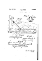
In the drawings Figure 1 is a perspective view of the brace and slide attached to a leg and table top and holding the leg locked: perpendicular to the plane of the table.
Figure 2 is a section of parts A and B taken through as of line XX in Fig. 1.
Figure 3 is a view showing the shape preferred for the notch H in part B.
Figure 4 is a plan View of the invention showing the leg closed and locked in this position.
Figure 5 is a cross section shown as line ZZ in Figure 1.
It will be evident that this invention may be applied with suitable modifications to tables of any number of legs, and may be used at other places and on other devices where these characteristics are needed.
The leg G is secured pivotally to the table at F in any suitable manner and the brace A is also pivotally held to the leg at C and at this joint is stressed in such a manner that it tends to spring in the direction of the arrow T. Such spring action tends to insert, lock and retain the brace A in the slots or notches H and I when brought to these positions along the slide.
The leg G is arranged to fold against the 0 underside of the table-top usually in parallel with one of its marginal edges. The slide-bar B is secured to the underside of the table in parallel with the respective leg when thus folded and disposed in spaced relation thereto, as shown in'Fig. 4:, to admit of the brace A lying therebetween with sufficient amplitude for the retraction of the brace from its engagement with either of said notches H or I.
Referring to Figure 3 it will be noticed that the notch H has a rounded or otherwise chamfered corner at O and that a slight taper to the notch is preferred and by reference to Figure 2it will be seen that the notch H is cut at an acute angle through the'slide bar B notch H, however, is also practical if out at right angles to the normal surface of slide bar B and may be so constructed.
Referring to Figure 5, O is a bolt or screw or other suitable pivot; N is a washer, A is a section of the brace, Q is a spacing bushing 0r washer adapted to take the clamping action of C without clamping A. M is a washer and G is a partial section of the leg.
It will be evident that when the set, or spring tension in the direction of the arrow T is reacted and transmitted by the joint shown at C that the washers N and M will take the stress and wear. The offsets shown at L and K are for the purpose of raising the bar from the table so that portion of A, which is shown bent at right angles and slotted' to'receive slide bar B, may slide along without friction or obstruction.
The locking of the brace in the slide bar at the open and closed positions is automatic and the release is a matter of a pressure in a direction opposite of the resilient urge or spring pressure aforementioned. It will be evident that all wear is taken by metallic surfaces and that a rapid and automatic lockingsystem is established that is rigid and practical." It'will also be noticed that this invention can be adapted to that type of table in which the legs fold to the center with facility as the slide bar B may be placed in any direction and by proper blocking beneath it, at any height from the table to allow one system of legs to cross and fold under another.
Changes in detail not affecting the spirit of this invention may be made such as change in the joint at C, a change in mounting methods of the slide bar B and other changes.
Having thus clearly described my invention I claim:
1. A folding table, consisting of a top, a plurality of legs pivotally connected with said top to fold in parallel with the underside of said top, a slide-bar associated with each said leg ri'gidly'secured 'to' the underside of said top and in parallel, spaced relation with the respective leg when in folded condition, said slide-bars each having a pair of notches formed in its lateral side proximate to the respectiveleg, anda brace pivotally connected to each said leg at one'end and formed with an aperture atits opposite end through which said slide-bar is extended, each said bracebeing in resilient engagement with said slide-bar to enter and be retained in said notches in the open and folded condition of the leg respectively.
2. A folding table, consisting of a top, a leg pivotally connected thereto, and'arranged to fold in parallel with the underside of said top,a-slide-bar rigidly secured to the underside of said top in parallel and in spaced relation' with said leg when in folded condition, said-slide-bar having a pair of spaced V- shaped notches in its lateraledge adjacent said leg, a brace pivotally connected at one end to the side of said leg proximate to said slide-bar andhaving a slotted hole in its other end through which said slide-bar extends, and means associated with the pivotal mounting of said brace for exerting spring-tension upon the brace-urging the brace into sliding engagement with the'slidebar and to'provide for the resilient seating of the brace within saidnotches, respectively, in the open and closed positions of the leg.
3. In a foldingtable, a leg pivotally connected to the undersideof the table-top and adapted to be folded into close relation with said" underside, a sli'de-bar secured to said underside of the table-top in parallel and in spaced relationtosaid leg when in folded condition and having a notch on its lateral side proximateto said leg, and a brace pivotally mounted on said leg and engageable at its opposite end with said slide-bar and to seatin said notch, said brace being formed with an ofi'set towards said slide-bar adjacent its outer end whereby the brace may lie between the slide-b ar and the leg when in folded condition and admit of the brace being disengaged from saidnotch.
'4. In a folding table, a leg pivotally connected thereto, aslide-bar rigidly mounted upon the underside ofthe table-top having a V-shaped notch upon its inner lateral edge, a brace pivotally mounted at one end upon a side of said leg opposing said-slide-bar and formed with an approximately right-angled bend at-its opposite end, said angular portion having a slotted hole through which said slide-bar extends, and means to resiliently urge said brace into sliding contact with said slide-bar whereby the brace will be caused to enter said notch to retain the leg in open condition.
i CHARLES E. OOWDIN.
Priority Applications (1)
| Application Number | Priority Date | Filing Date | Title |
|---|---|---|---|
| US416023A US1854887A (en) | 1929-12-23 | 1929-12-23 | Folding table |
Applications Claiming Priority (1)
| Application Number | Priority Date | Filing Date | Title |
|---|---|---|---|
| US416023A US1854887A (en) | 1929-12-23 | 1929-12-23 | Folding table |
Publications (1)
| Publication Number | Publication Date |
|---|---|
| US1854887A true US1854887A (en) | 1932-04-19 |
Family
ID=23648203
Family Applications (1)
| Application Number | Title | Priority Date | Filing Date |
|---|---|---|---|
| US416023A Expired - Lifetime US1854887A (en) | 1929-12-23 | 1929-12-23 | Folding table |
Country Status (1)
| Country | Link |
|---|---|
| US (1) | US1854887A (en) |
Cited By (4)
| Publication number | Priority date | Publication date | Assignee | Title |
|---|---|---|---|---|
| US2527045A (en) * | 1947-02-27 | 1950-10-24 | Automatic Table Co Inc | Leg positioning mechanism for folding tables |
| US2621992A (en) * | 1949-01-25 | 1952-12-16 | Enfred W Anderson | Locking brace for folding legs of tables |
| US2729527A (en) * | 1954-10-20 | 1956-01-03 | Arvid J Anderson | Combination folding leg hinge, latch, and brace |
| US3025121A (en) * | 1959-11-12 | 1962-03-13 | Nettie O Smith | Paper hanger's table and paste container |
-
1929
- 1929-12-23 US US416023A patent/US1854887A/en not_active Expired - Lifetime
Cited By (4)
| Publication number | Priority date | Publication date | Assignee | Title |
|---|---|---|---|---|
| US2527045A (en) * | 1947-02-27 | 1950-10-24 | Automatic Table Co Inc | Leg positioning mechanism for folding tables |
| US2621992A (en) * | 1949-01-25 | 1952-12-16 | Enfred W Anderson | Locking brace for folding legs of tables |
| US2729527A (en) * | 1954-10-20 | 1956-01-03 | Arvid J Anderson | Combination folding leg hinge, latch, and brace |
| US3025121A (en) * | 1959-11-12 | 1962-03-13 | Nettie O Smith | Paper hanger's table and paste container |
Similar Documents
| Publication | Publication Date | Title |
|---|---|---|
| US2576287A (en) | Pedestal table with pivoted drop leaf and folding base | |
| US2181966A (en) | Fastening device | |
| US1854887A (en) | Folding table | |
| US2178248A (en) | Folding table | |
| US2796268A (en) | Folding table leg bracket | |
| US1917903A (en) | Basket | |
| US1719662A (en) | Snap connection | |
| US2227871A (en) | Joint between two objects | |
| US1703649A (en) | Adjustable strap for blectric-lighting fixtures | |
| US2690369A (en) | Folding table leg hinge and latch structure | |
| US1951888A (en) | Folding table | |
| US2704236A (en) | Table aligning devices | |
| US1985620A (en) | Refectory table | |
| US2955820A (en) | Article aligning fixture with quickacting clamping devices | |
| US2869902A (en) | Tubular furniture | |
| US1567602A (en) | Tapeline measure | |
| US2247397A (en) | Loose-leaf binder | |
| US1313482A (en) | Flexible rule | |
| US1751536A (en) | Table | |
| US972356A (en) | Ironing-board. | |
| US2115727A (en) | Folding table | |
| US888498A (en) | Calipers and dividers. | |
| US1298249A (en) | Folding-leg furniture. | |
| US1626189A (en) | Table slide | |
| US622578A (en) | Tergren |