US1854871A - Beehive - Google Patents
Beehive Download PDFInfo
- Publication number
- US1854871A US1854871A US280883A US28088328A US1854871A US 1854871 A US1854871 A US 1854871A US 280883 A US280883 A US 280883A US 28088328 A US28088328 A US 28088328A US 1854871 A US1854871 A US 1854871A
- Authority
- US
- United States
- Prior art keywords
- chamber
- hive
- bee
- enclosures
- chambers
- Prior art date
- Legal status (The legal status is an assumption and is not a legal conclusion. Google has not performed a legal analysis and makes no representation as to the accuracy of the status listed.)
- Expired - Lifetime
Links
- 238000005192 partition Methods 0.000 description 25
- 241000257303 Hymenoptera Species 0.000 description 11
- 244000144987 brood Species 0.000 description 5
- 235000012907 honey Nutrition 0.000 description 5
- 238000003780 insertion Methods 0.000 description 5
- 230000037431 insertion Effects 0.000 description 5
- 208000024780 Urticaria Diseases 0.000 description 4
- 230000009545 invasion Effects 0.000 description 3
- XEEYBQQBJWHFJM-UHFFFAOYSA-N Iron Chemical compound [Fe] XEEYBQQBJWHFJM-UHFFFAOYSA-N 0.000 description 2
- 238000009395 breeding Methods 0.000 description 2
- 230000001488 breeding effect Effects 0.000 description 2
- 230000035622 drinking Effects 0.000 description 2
- 238000000926 separation method Methods 0.000 description 2
- 238000004140 cleaning Methods 0.000 description 1
- 238000004891 communication Methods 0.000 description 1
- 238000010276 construction Methods 0.000 description 1
- 235000013305 food Nutrition 0.000 description 1
- 238000003306 harvesting Methods 0.000 description 1
- 229910052742 iron Inorganic materials 0.000 description 1
- 238000000034 method Methods 0.000 description 1
- 238000004321 preservation Methods 0.000 description 1
- 239000007787 solid Substances 0.000 description 1
- 238000003860 storage Methods 0.000 description 1
- 239000000725 suspension Substances 0.000 description 1
Images
Classifications
-
- A—HUMAN NECESSITIES
- A01—AGRICULTURE; FORESTRY; ANIMAL HUSBANDRY; HUNTING; TRAPPING; FISHING
- A01K—ANIMAL HUSBANDRY; AVICULTURE; APICULTURE; PISCICULTURE; FISHING; REARING OR BREEDING ANIMALS, NOT OTHERWISE PROVIDED FOR; NEW BREEDS OF ANIMALS
- A01K47/00—Beehives
Definitions
- the present invention relates to bee-hives, and particularly to bee-hives in which a plu rality of chambers arranged one above the other are provided, which chambers may bc S sub-divided into individual enclosures by means of removable slidable partition walls.
- One object of the invention is to construct a beeshive of this kind in such a manner that, during the four seasons of the year, it can be adapted by means of very few manipulations to the requirements of the time being 1n regard to brood increase, wmtering, col- -onization of the various swarms, etc.
- the honey-storage chamber arranged above the upper chamber is separated from this latter by means of a two-part grid, which, in view of the fact that the upper chamber, for the purpose of the preservation of warmth in winter, is not provided with a door, is adapted to allow of the insertion of the upper partition wall from above through an aperture.
- the parts of the said grid may, for the purpose of brood increase, be temporarily entirely removed in order to allow the queen bee also to have access to the upper part.
- the comb frames are mounted in a slide member, the one transverse strip of which, when the slide member is inserted, comes into position opposite to the lower hive entrances and thus offers eiiicient protection against thieving invaders.
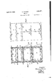
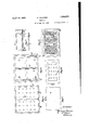
- Fig. l isv a cross section through the hive
- ⁇ Fig. 2 is an elevation of the front wall
- Fig. 3 is a longitudinal section of the hive
- Fig. 4 is an elevation of the rear wall
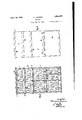
- Fig. 5 shows the grid separating the winter quarters or enclosures from the honeycollecting chambers
- Fig. 6 shows the partition Hoor separating the two chambers together with the slide strips
- Fig. 7 shows the slide member for the comb frames of the lower chamber
- Fig. 8 shows a detail of a guide strip
- Figs. 9 and l0l show two partition walls
- Fig. '11 shows the individual doors yarranged at the rear.
- the constructional form of the bee-hive according to the present invention illustrated on the accompanying drawings consists of a housing A and two top structures B and C arranged upon said housing, the top structure C being adapted to be closed by meansv of a cover 1.
- the housing A is divided by means of a fixed partition floor 2 into two chambers E and F.
- the twochambers E and F can each be sub-divided according to require'- ments into two enclosures a, b and c, d respectively by means of removable slidable partition walls 3 and 4.
- Comb frames 5 are inserted in the chamber E through admission doors provided on the rear wall. Only the chamber E is provided with standing comb frames, whilst in the top structures B, C and in theV chamber F, the comb frames 5 are suspended. ⁇ On the bot-- tom of the chamber Ea slide member 6 (see Fig. 7) for supporting the lower comb frames 5 is placed. V
- a guide strip 7 (see Fig. 8) is arranged on the under side of the partition floor 2.
- guiding grooves 8 and 22 respectively are provided in the slide member 6', and two corresponding guiding grooves 23 and 24 are likewise provided on the underside of the partition floor 2.
- the partition wall 21 may also take the form of a grid.
- the enclosure e divided off by the partition wall 21, serves, as hereinafter described, for the separation of the queen and is provided for the purpose of permitting her egress into the open air with a special exit hole 32 (see Fig. 2) in the front wall of the housing.
- the removable slide member 6 is provided on its transverse strips 9 and 10 with grooves in which the comb frames are inserted.
- the transverse strip 10 is provided on its underneath part with curved recesses through which bees falling o on the outer side from the frame can get back into the enclosures a and I).
- the beehive according to the present construction belongs to the known type in which the comb frames are arranged normal to the two entrances. and in the present case, the transverse strip 9 lies immediately opposite to the entrances 11 and 12.
- the transverse strip 9 is provided with two drinking holes 17 arranged opposite to the entrances, through which holes drinking vessels can be pushed into the bee-hive.
- This arrangement of the transverse strip 9 opposite to the entrances 11 and 12 plays an important part in the defensive fight of the bees when thieving invasions take place. In such cases the invading bees have irst to climb up the vertical surface of the transverse strip 9 and are met at the top by the defending bees posted in the intermediate spaces between the frames and are stung.
- the chamber F is divided into two enclosures c and d by the insertion of a partition wall 4 and is separated from the top structure B by means of two grids 25 and 18 which are also constructed so that they can be easily inserted and are separated from one another by means of an intermediate space 26.
- the partition wall 4 can only be inserted from above through the slot 26 of the grid after the lifting off of the top structure B. and is held in place on the bottom 2 by means of two strips 27 provided thereon.
- the bottom is provided in proximity to the side walls ot the chamber with slots 28 and 29 for communication with the enclosures a and e below, which slots can be covered up by means of slide strips 30 and 31.
- the one slot 29 is permanently covered by a grating.
- the comb frames 5 are suspended.
- the comb frames are provided with suspension lugs 33 and 34, which are inserted into recesses 35 provided on the upper edge of the chamber A, and of the top structures B and C respectively.
- iron bands 36 are fixed, which project beyond the edges of the chamber and serve to prevent the top structures B and C from sliding off laterally.
- the top structure C is covered by means ot a cover 1 which is provided with two food holes 37, which can be closed by means ot plugs 38.
- a frame 39 is iXed which serves for the reception of the panel doors 40, 41 and 42, which are provided with window-like openings covered with gauze.
- a solid cover 43 pivoted by means of hinges to the rear wall of the chamber serves for the complete closure ot' the panel doors. ln order to be able to clean the bottom of the chamber F a cleaning hole 44 (see Fig. 4) having a closure is provided on the rear wall ot the chamber at the height of the bottom 2.
- the method of employing the bee-hive at the diiiierent seasons of the year is as follows:
- the grids 18 or 25 are removed for the purpose of brood increase, in order that the queen can place her brood in the comb trames of the honey chamber B above.
- partition wall 4 is removed and the remaining bees distribute themselves over all parts of the hive.
- the entrances to the winter quarters remain closed in order to compel the bees to pass through the lower entrances and thus to occupy the whole of the hive.
- the bee-hive according to the present invention is preferably so dimensioned that the comb frames of the usual known types of bee-hives can also be employed.
- the bee-hive according to the present invention is also of great importance for the breeding of queens, inasmuch as for this purpose the two lower enclosures a and b can also be employed.
- the bee-hive permits of division into swarms up to the number of four, and also renders it easy to transfer the swarms from the said hive to another one, as the comb frames are easily removable.
- the bee-hive presents great advantages in respect to the brood increase in the spring.
- the bee-hive protects the bees effectively from the thieving incursions of neighbouring swarms.
- a bee-hive comprising in combination: an upper chamber, a removable slidable partition wall dividing said upper chamber into two enclosures, a lower chamber arranged below said upper chamber, a removable slidable partition wall dividing said lower chamber into two enclosures, a partition floor separating said upper chamber from said lower chamber and provided at each side with a slot passing through said iioor, and slide strips adapted to open and close said slots.
- each of said chambers is provided on its front wall with entrances for each of the said four enclosures.
- a bee-hive comprising in combination: an upper chamber, a removable slidable partition wall dividing said upper chamber into two enclosures, a lower chamber arranged below said upper chamber and provided with a door, a removable slidable partition wall dividing said lower chamber into two enclosures, a partition Hoor separating said upper chamber from said lower chamber and provided at each side with a slot passing through said floor, slide strips for opening and closing said slots, honey collecting chambers mounted on the top of said upper chamber, and a two-part grid memberV separating said upper chamber from said honey collecting chambers, said grid member being spaced to allow of the insertion or removal of said partition wall of said upper chamber from above after said honey collecting chambers have been lifted ott said upper chamber.
- a bee-hive having a plurality of chambers arranged one above the other, the combination of: a lower chamber provided with entrance holes, a slide member arranged in said lower chamber and provided with grooves, comb frames in the grooves in said slide member, and a transverse strip on said slide member arranged closely in front of the entrance holes of said lower chamber, whereby said strip oi'ers facilities for the inmates of the hive to defend themselves against invasion.
- a bee-hive having a plurality of chambers arranged one above the other, the combination of: a lower chamber provided with entrance holes, a removable slide member arranged in said lower chamber, and a transverse strip on said slide member arranged closely in Jfront of the entrance holes of said lower chamber, whereby said strip offers facilities for the inmates of the hive to defend themselves against invasion.
Landscapes
- Life Sciences & Earth Sciences (AREA)
- Environmental Sciences (AREA)
- Animal Husbandry (AREA)
- Biodiversity & Conservation Biology (AREA)
- Catching Or Destruction (AREA)
Description
H. TRAUNER April 19, 1932.
BEEHIVE Filed May 25, 1928 v 5 Sheets-Sheet H. TRAUNER April 19, 1932.
BEEHIVE Filed May 26, 1928 5 Sheets-Sheet 2 www@ H. TRAUNER April 19, 1932.
xzusruw:v
s sheets-sheet 5 Filed May 2G, 1928 /hventon' mung Sh@ m mf ,.v MMI @5E whew. Q N QN O Q Q o ,.wwwwwmwUHH O C O hw, e Q o o n O Q C .Q
Patented Apr. 19, i932 HEINRICH TRAUNER, OF FROHSDORF, AUSTRIA BEEHIVE Application led May 26, 1928, Serial No. 280,883, and in Austria .Tune 2, 1927.
The present invention relates to bee-hives, and particularly to bee-hives in which a plu rality of chambers arranged one above the other are provided, which chambers may bc S sub-divided into individual enclosures by means of removable slidable partition walls.
One object of the invention is to construct a beeshive of this kind in such a manner that, during the four seasons of the year, it can be adapted by means of very few manipulations to the requirements of the time being 1n regard to brood increase, wmtering, col- -onization of the various swarms, etc. A
further very important object of the inven- 1|!l tion is to render it possible to enable two chamber by the insertion therein of a partition wall, by means of slots provided in a partition floor arranged between the said two Chambers, said slots being located in proximity to the sides of the chambers and being capable of being opened and closed by means of slide strips. In the two chambers entrances are provided leading to each of the four enclosures formed as above described, which entrances, when the slide strips havebeen pushed into place allow the bees of four different swarms to enter four enclosures which are entirely separated from one another. The honey-storage chamber arranged above the upper chamber is separated from this latter by means of a two-part grid, which, in view of the fact that the upper chamber, for the purpose of the preservation of warmth in winter, is not provided with a door, is adapted to allow of the insertion of the upper partition wall from above through an aperture. The parts of the said grid may, for the purpose of brood increase, be temporarily entirely removed in order to allow the queen bee also to have access to the upper part. In
the lower chamber the comb frames are mounted in a slide member, the one transverse strip of which, when the slide member is inserted, comes into position opposite to the lower hive entrances and thus offers eiiicient protection against thieving invaders.
A preferred constructional'form of a beehive according to the invention is illustrated by way of example in the accompanying drawings, in which:
Fig. l isv a cross section through the hive,
` Fig. 2 is an elevation of the front wall,
Fig. 3 is a longitudinal section of the hive,
Fig. 4 is an elevation of the rear wall,
Fig. 5 shows the grid separating the winter quarters or enclosures from the honeycollecting chambers,
Fig. 6 shows the partition Hoor separating the two chambers together with the slide strips,
Fig. 7 shows the slide member for the comb frames of the lower chamber,
Fig. 8 shows a detail of a guide strip,
Figs. 9 and l0l show two partition walls, and
Fig. '11 shows the individual doors yarranged at the rear.
The constructional form of the bee-hive according to the present invention illustrated on the accompanying drawings consists of a housing A and two top structures B and C arranged upon said housing, the top structure C being adapted to be closed by meansv of a cover 1. The housing A is divided by means of a fixed partition floor 2 into two chambers E and F. The twochambers E and F can each be sub-divided according to require'- ments into two enclosures a, b and c, d respectively by means of removable slidable partition walls 3 and 4. n 1
For the purpose of holding the comb frames at their upper parts a guide strip 7 (see Fig. 8) is arranged on the under side of the partition floor 2. For the purpose of the insertion of the lower partition wall 8 and a further partition wall 21, guiding grooves 8 and 22 respectively are provided in the slide member 6', and two corresponding guiding grooves 23 and 24 are likewise provided on the underside of the partition floor 2. The partition wall 21 may also take the form of a grid. The enclosure e divided off by the partition wall 21, serves, as hereinafter described, for the separation of the queen and is provided for the purpose of permitting her egress into the open air with a special exit hole 32 (see Fig. 2) in the front wall of the housing.
. The removable slide member 6 is provided on its transverse strips 9 and 10 with grooves in which the comb frames are inserted. The transverse strip 10 is provided on its underneath part with curved recesses through which bees falling o on the outer side from the frame can get back into the enclosures a and I).
On the front wall of the bee-hive at the height of the bottom of the chambers E and F the entrances 11, 12, 13 and 14 and the entry boards 15 and 16 for the entry and exit of the bees are arranged. For the purpose of separation and for the avoidance of tights amongst the bees separating screens 19 and 20 are also provided on the front wall of the bee-hive.
The beehive according to the present construction belongs to the known type in which the comb frames are arranged normal to the two entrances. and in the present case, the transverse strip 9 lies immediately opposite to the entrances 11 and 12. The transverse strip 9 is provided with two drinking holes 17 arranged opposite to the entrances, through which holes drinking vessels can be pushed into the bee-hive. This arrangement of the transverse strip 9 opposite to the entrances 11 and 12 plays an important part in the defensive fight of the bees when thieving invasions take place. In such cases the invading bees have irst to climb up the vertical surface of the transverse strip 9 and are met at the top by the defending bees posted in the intermediate spaces between the frames and are stung.
The chamber F is divided into two enclosures c and d by the insertion of a partition wall 4 and is separated from the top structure B by means of two grids 25 and 18 which are also constructed so that they can be easily inserted and are separated from one another by means of an intermediate space 26. The partition wall 4 can only be inserted from above through the slot 26 of the grid after the lifting off of the top structure B. and is held in place on the bottom 2 by means of two strips 27 provided thereon. The bottom is provided in proximity to the side walls ot the chamber with slots 28 and 29 for communication with the enclosures a and e below, which slots can be covered up by means of slide strips 30 and 31. The one slot 29 is permanently covered by a grating. In the enclosures c, d of the chamber F, as also in the top structures B and C the comb frames 5 are suspended. For this purpose the comb frames are provided with suspension lugs 33 and 34, which are inserted into recesses 35 provided on the upper edge of the chamber A, and of the top structures B and C respectively. On the upper rim of the chamber A, as also on the upper rim of the irst top structure B, iron bands 36 are fixed, which project beyond the edges of the chamber and serve to prevent the top structures B and C from sliding off laterally.
The top structure C is covered by means ot a cover 1 which is provided with two food holes 37, which can be closed by means ot plugs 38.
On the back' wall of the chambers a frame 39 is iXed which serves for the reception of the panel doors 40, 41 and 42, which are provided with window-like openings covered with gauze.
A solid cover 43 pivoted by means of hinges to the rear wall of the chamber serves for the complete closure ot' the panel doors. ln order to be able to clean the bottom of the chamber F a cleaning hole 44 (see Fig. 4) having a closure is provided on the rear wall ot the chamber at the height of the bottom 2.
The method of employing the bee-hive at the diiiierent seasons of the year is as follows:
In the winter there are two swarms of bees -in the so-called winter quarters or enclosures c and CZ, which are separated from one another by the partition wall 4. The entrances leading direct to the winter quarters are closed. IThe two slide strips remain open, in order that the ventilating air which has first become heated in the lowest chamber, can enter.
In the spring, before the harvest of honey begins, the grids 18 or 25 are removed for the purpose of brood increase, in order that the queen can place her brood in the comb trames of the honey chamber B above.
At the beginning of the summer one of the two queens in the two winter enclosures is removed. rlhe second queen is placed in the queen chamber e. rEhe slide strip above the queen chamber is in the open position, but the slot 29 remains permanently covered by a grating.
After this the partition wall 4 is removed and the remaining bees distribute themselves over all parts of the hive. The entrances to the winter quarters remain closed in order to compel the bees to pass through the lower entrances and thus to occupy the whole of the hive.
In the autumn the bee-keeper is desirous of increasing the swarms by the introduction of breeding queens into the four enclosures, and
for this purpose the slide strips must be closed and the hive entrances to the winter quarters must be opened. In this way each swarm is kept separate and a transference can then easily be effected by removal of the comb frames to other hives.
The bee-hive according to the present invention is preferably so dimensioned that the comb frames of the usual known types of bee-hives can also be employed.
The construetional form of bee-hive described, renders it possible to permit two swarms to pass the winter in the so-called winter quarters c and cl of the chamber F and to keep the said quarters warm. The ventilating air passes in this case through the lower hive entrances 11 and 12 into the interior of the irst chamber and becomes warmed in this latter, and it is only after this that the said air passes through the slots 28 and 29 of the bottom 2 into the winter quarters.
The bee-hive according to the present invention is also of great importance for the breeding of queens, inasmuch as for this purpose the two lower enclosures a and b can also be employed.
Furthermore, the bee-hive permits of division into swarms up to the number of four, and also renders it easy to transfer the swarms from the said hive to another one, as the comb frames are easily removable. Moreover, the bee-hive presents great advantages in respect to the brood increase in the spring. Finally, the bee-hive protects the bees efectively from the thieving incursions of neighbouring swarms.
I claim:
1. A bee-hive comprising in combination: an upper chamber, a removable slidable partition wall dividing said upper chamber into two enclosures, a lower chamber arranged below said upper chamber, a removable slidable partition wall dividing said lower chamber into two enclosures, a partition floor separating said upper chamber from said lower chamber and provided at each side with a slot passing through said iioor, and slide strips adapted to open and close said slots.
2. A bee-hive as specied in claim 1, wherein each of said chambers is provided on its front wall with entrances for each of the said four enclosures.
3. A bee-hive comprising in combination: an upper chamber, a removable slidable partition wall dividing said upper chamber into two enclosures, a lower chamber arranged below said upper chamber and provided with a door, a removable slidable partition wall dividing said lower chamber into two enclosures, a partition Hoor separating said upper chamber from said lower chamber and provided at each side with a slot passing through said floor, slide strips for opening and closing said slots, honey collecting chambers mounted on the top of said upper chamber, and a two-part grid memberV separating said upper chamber from said honey collecting chambers, said grid member being spaced to allow of the insertion or removal of said partition wall of said upper chamber from above after said honey collecting chambers have been lifted ott said upper chamber.
4. In a bee-hive having a plurality of chambers arranged one above the other, the combination of: a lower chamber provided with entrance holes, a slide member arranged in said lower chamber and provided with grooves, comb frames in the grooves in said slide member, and a transverse strip on said slide member arranged closely in front of the entrance holes of said lower chamber, whereby said strip oi'ers facilities for the inmates of the hive to defend themselves against invasion.
5. In a bee-hive having a plurality of chambers arranged one above the other, the combination of: a lower chamber provided with entrance holes, a removable slide member arranged in said lower chamber, and a transverse strip on said slide member arranged closely in Jfront of the entrance holes of said lower chamber, whereby said strip offers facilities for the inmates of the hive to defend themselves against invasion.
Signed at Vienna, Austria, this 16th day of May, 1928.
HEINRICH TRAUNER.
Applications Claiming Priority (1)
| Application Number | Priority Date | Filing Date | Title |
|---|---|---|---|
| AT1854871X | 1927-06-02 |
Publications (1)
| Publication Number | Publication Date |
|---|---|
| US1854871A true US1854871A (en) | 1932-04-19 |
Family
ID=3689129
Family Applications (1)
| Application Number | Title | Priority Date | Filing Date |
|---|---|---|---|
| US280883A Expired - Lifetime US1854871A (en) | 1927-06-02 | 1928-05-26 | Beehive |
Country Status (1)
| Country | Link |
|---|---|
| US (1) | US1854871A (en) |
Cited By (2)
| Publication number | Priority date | Publication date | Assignee | Title |
|---|---|---|---|---|
| US5741170A (en) * | 1996-07-25 | 1998-04-21 | Orletsky; Darryl W. | Modular beehive |
| ITLC20090003A1 (en) * | 2009-01-28 | 2010-07-29 | Marialuisa Romano' | DEVICE HAVING TITLE: "TECHNO ARNIA", ALSO KNOWN AS ARNIA, PROPERLY STUDIED TO OPTIMIZE THE MATERIALS THAT MAKE IT AND PROVIDE THE DEVICE OF ITSELF, OF AN INNOVATIVE INNER BRACE THAT ALLOWS A NEW AND INTERES |
-
1928
- 1928-05-26 US US280883A patent/US1854871A/en not_active Expired - Lifetime
Cited By (2)
| Publication number | Priority date | Publication date | Assignee | Title |
|---|---|---|---|---|
| US5741170A (en) * | 1996-07-25 | 1998-04-21 | Orletsky; Darryl W. | Modular beehive |
| ITLC20090003A1 (en) * | 2009-01-28 | 2010-07-29 | Marialuisa Romano' | DEVICE HAVING TITLE: "TECHNO ARNIA", ALSO KNOWN AS ARNIA, PROPERLY STUDIED TO OPTIMIZE THE MATERIALS THAT MAKE IT AND PROVIDE THE DEVICE OF ITSELF, OF AN INNOVATIVE INNER BRACE THAT ALLOWS A NEW AND INTERES |
Similar Documents
| Publication | Publication Date | Title |
|---|---|---|
| US4135265A (en) | Bee hive | |
| CN101115386B (en) | beehive cover | |
| NL8101797A (en) | BEING HOUSE. | |
| CN107047377A (en) | Beehives that improve the environment for bees | |
| US1854871A (en) | Beehive | |
| WO2016087883A1 (en) | Multihive | |
| US2128000A (en) | Beehive | |
| CA2911008C (en) | Horizontal top-bar beehive | |
| US1816631A (en) | Top-entrance beehive | |
| US1584775A (en) | Beehive | |
| SU900831A1 (en) | Container beehive | |
| US470789A (en) | Bee-hive | |
| DE3327965A1 (en) | Device for efficient keeping and breeding of bees | |
| US314972A (en) | mitchell | |
| US109201A (en) | Improvement in bee-hives | |
| SU843893A1 (en) | Pavilion beehive | |
| CN217364263U (en) | Prevent multi-functional beehive of wasp | |
| US199328A (en) | Improvement in bee-hives | |
| US20230371477A1 (en) | Beekeeping hive and method of beekeeping | |
| US141443A (en) | Improvement in bee-hives | |
| US144847A (en) | Improvement in bee-hives | |
| RU2048761C1 (en) | Cassette-type hive | |
| US131296A (en) | Improvement in bee-hives | |
| SU812253A1 (en) | Beehive ceiling | |
| US165501A (en) | Improvement iiss bee-hives |