US1854852A - Method for the construction and facing of roadways - Google Patents
Method for the construction and facing of roadways Download PDFInfo
- Publication number
- US1854852A US1854852A US332522A US33252229A US1854852A US 1854852 A US1854852 A US 1854852A US 332522 A US332522 A US 332522A US 33252229 A US33252229 A US 33252229A US 1854852 A US1854852 A US 1854852A
- Authority
- US
- United States
- Prior art keywords
- paving
- frames
- supports
- construction
- substructure
- Prior art date
- Legal status (The legal status is an assumption and is not a legal conclusion. Google has not performed a legal analysis and makes no representation as to the accuracy of the status listed.)
- Expired - Lifetime
Links
- 238000010276 construction Methods 0.000 title description 9
- 238000000034 method Methods 0.000 title description 3
- 239000000463 material Substances 0.000 description 14
- 239000010426 asphalt Substances 0.000 description 5
- 239000004567 concrete Substances 0.000 description 5
- 229910001018 Cast iron Inorganic materials 0.000 description 4
- 239000002184 metal Substances 0.000 description 4
- 229910052751 metal Inorganic materials 0.000 description 4
- 239000004568 cement Substances 0.000 description 3
- 230000002452 interceptive effect Effects 0.000 description 3
- 238000012986 modification Methods 0.000 description 3
- 230000004048 modification Effects 0.000 description 3
- 239000004575 stone Substances 0.000 description 3
- XLYOFNOQVPJJNP-UHFFFAOYSA-N water Substances O XLYOFNOQVPJJNP-UHFFFAOYSA-N 0.000 description 3
- 239000002023 wood Substances 0.000 description 3
- 229910000754 Wrought iron Inorganic materials 0.000 description 2
- 239000011521 glass Substances 0.000 description 2
- 229910000906 Bronze Inorganic materials 0.000 description 1
- CWYNVVGOOAEACU-UHFFFAOYSA-N Fe2+ Chemical compound [Fe+2] CWYNVVGOOAEACU-UHFFFAOYSA-N 0.000 description 1
- 229910000831 Steel Inorganic materials 0.000 description 1
- 239000010974 bronze Substances 0.000 description 1
- KUNSUQLRTQLHQQ-UHFFFAOYSA-N copper tin Chemical compound [Cu].[Sn] KUNSUQLRTQLHQQ-UHFFFAOYSA-N 0.000 description 1
- 239000000945 filler Substances 0.000 description 1
- 238000003780 insertion Methods 0.000 description 1
- 230000037431 insertion Effects 0.000 description 1
- 230000001788 irregular Effects 0.000 description 1
- 239000004570 mortar (masonry) Substances 0.000 description 1
- 230000002093 peripheral effect Effects 0.000 description 1
- 238000002360 preparation method Methods 0.000 description 1
- 239000011150 reinforced concrete Substances 0.000 description 1
- 230000008439 repair process Effects 0.000 description 1
- 230000000284 resting effect Effects 0.000 description 1
- 239000005060 rubber Substances 0.000 description 1
- 239000010959 steel Substances 0.000 description 1
- -1 various fibres Substances 0.000 description 1
Images
Classifications
-
- E—FIXED CONSTRUCTIONS
- E01—CONSTRUCTION OF ROADS, RAILWAYS, OR BRIDGES
- E01C—CONSTRUCTION OF, OR SURFACES FOR, ROADS, SPORTS GROUNDS, OR THE LIKE; MACHINES OR AUXILIARY TOOLS FOR CONSTRUCTION OR REPAIR
- E01C3/00—Foundations for pavings
- E01C3/006—Foundations for pavings made of prefabricated single units
Definitions
- The; present invention relates to the construction and the facing of roads, streets, avenues, bridges and the like in which the construction and repairing thereof requires rapidly executed work and also employs a variety of materials'such as paving stone, asphalt, wood blocks, bitumen, various fibres, rubber, cement, concrete, glass and the like.
- An object of the invention isto provide a system which requires two operations. In the first place, the preparation of the road-bed which consists of a'layer of concrete which is sufficiently thick and substantial to ensure a long life, and in the second place the placing upon such road-bed of interchangeably" flat surface members of slabs-without the necessity of interfering with the road-bed or substructure.
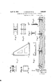
- I Figure 1 is a plan view of a metallic frame of wrought or cast iron having a triangular shape which is aperturedand provided with flanges so as tovform a receptacle for the paving material itself,
- ' igure'2 is a cross sectional view of the construction-shown'in Figure 1 takenon a line extending through the centers of the apertures in-thebase of the triangular receptacle
- Figure 3 is a front elevation upon a slightly enlargedscale of a cast iron support for such receptacle of rectangular shape which will supportthe frames when they are secured to the securing 'means used for securing the "frame t'othe support
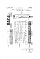
- Figure 7 is aip'artial cross section of the substructure which consists of a layer of concrete in which the spikes are inserted,
- Figure 8 is as'section of the'road-bed showing adraining trough under the paving structure for removing anywater
- Figure 9 is a portion of a road-bed showing howalongitudinal section of a frame will be used for the support of the various paving materials such as wood blocks, stones, asphalt or the like,
- Figure 10 is a plan view of a complete roadwayshowing the arrangement of four of the frames and their postion in the structure
- Figure 11- is a cross sectionalview of Figure 10 taken through the securing means for the supports and-the pavingpframes,
- Figure 12 is an exploded view showing a modification of the securing means
- FIG. 13 is a partial elevation'al and partly sectional view of a modified constru'ction
- Figure 14 is a topplan view of the support shown in Figure 13.
- Figure 7 shows apart of the road-bed or substructure after the first operation has been completed.
- the foundation herein consists of a bed of cement or concrete or mortar which has a sufficient depth to allow the supports to be embedded thereinso that the topsof said supports are flushwith the upper surface of the concrete.
- the supports are mounted in the substructurein accordance with the size and positioning of the framesas shown in Figuresl andQ' which are in turn secured to the supports by the .screwspikes shown in Figure 6.
- FIG. 8 at 576 is shown a culvert jor drain for leading away the water which will collect between the surface of the bed and the removable part of-the roadway. It'is understood that the number .ofsuch culvertsis not limited, nor is the positioning of the same limited since these factors will depend upon the slope and width of the roadway as well as other factors such as the particular location of the roadway. As a general rule however, the culverts will start from the embedded axis of the roadway and then lead off the collected water to the particular sewers provided.
- the substructure therefore constitutes, according to the present invention, a permanent part of the road-bed whose life is unlimited. If for any reason future work is to be undertaken such as sewers, water or gas piping or electric cables, the substructure or reinforced concrete may be prepared in such a manner that all of such work can be performed below the surface and without interfering with the paved part of the roadway. It is also pointed out that such repairs would not necessitate the stoppage of traific.
- the frames preferably of the form shown in Figures 1 and 2 are placed in position with the paving material of any desired type therein. These frames with the paving material therein form the removable part of the arrangement according to this invention.
- the facing material in such frames such as stone, wood, asphalt, bitumen, cement, glass, rubher and the like, may be placed in position in the factory and may be brought to the place at which they are to be secured to the substructure after having been checked, dried and prepared so that their dimensions will be exactly correct and the material placed therein first verified as to its proper quality.
- the frames constitute triangular slabs of the same shape as the triangular frame shown in Figures 1 and 2 which are composed of metal and into which the paving material has been molded and subjected to a high pressure in order to force such paving material within the metal frame as shown for instance in Figure 9. It might be pointed out that this subjecting of the paving material to high pressure when placed in a slab at the time manufactured will also serve to render the surface of the slab stronger and harder.
- holes 57 are postioned which correspond in position to the holes 51 in the frame and these holes 57 serve for the insertion of the screw spikes as filling thereof with paving, the flanges are somewhat lower than the flanges shown in the frame in Figure 9 which shows that the filling material extends above the edge 59 of the frame by a certain height because the metal must be protected so as to permit the refilling of the frames after the paving therein has been subjected to the wear of the roadway.
- the screw spike shown in Figure 6 comprises a metal rod having a certain diameter at the upper part and provided with a square or hexagonal head with which the wrench may cooperate for screwing purposes.
- the spike is of the same height as the height of the paving in the frame.
- Figures 10 and 11 wherein Figure 10 shows a plan view and Figure 11 shows a sectional view, the particular arrangement of the frames and their position with reference to the supporting members to which they are bolted is shown.
- the screw spikes or screws secured to the paving slabs and then to the supports embedded in the ground were screwed directly into the cast iron supports.
- Figure 12 It will be noted that the nut is placed in a slot provided in the support and that the screw spike cooperates with this nut in the support. It is evident that the nut located in the support may be removed and replaced at any time it is desired.
- paving blocks are utilized for the paving surface. As pointed out above however, any type of paving whatsoever may be used. When paving blocks are used as in Figure 10, then of course certain of the blocks will have irregular shapes along the diagonal lines. In such case it is merely necessary to out the blocks with a tool to the requisite shape which is very easily done and fitted into the recess provided for it.
- a roadbed comprising a substructure, supporting means embedded in the substructure substantially flush with the surface thereof, frames imposed on said substructure and supporting means having upstanding peripheral flanges, a filler of pavingvmaterial in the frames, the edges of the material being coextensive with the outsides of the flanges so that there may be continuous abutment of the paving material in adjoining frames, and fastening means passing through the paving material and frames into the supporting means.
- a roadbed comprising a plurality of paving sections, an equal plurality of container frames in which the sections are packed, flanged supports upon which adjoining corners of the frames are rested, and fastening means passing through the approximate corners of the paving sections and frames into the flanges of the supports thus both securing the paving sections and designating the approximate contour thereof.
- a roadbed comprising a plurality of paving sections, a container frame for each of the sections, supports upon which the frames are rested, and studs extending through the paving sections being screwed into the supports, having shoulders bearing on the frames and having heads close to the surface for ready access.
- a roadbed comprising supports having slotted flanges, paving sections, frames containing said sections and resting on the supports, shouldered studs bearing on the frames to hold them down, having threaded ends transfixing the slotted flanges, and nuts situated in the slots into which nuts said ends are screwed.
Landscapes
- Engineering & Computer Science (AREA)
- Architecture (AREA)
- Civil Engineering (AREA)
- Structural Engineering (AREA)
- Road Paving Structures (AREA)
Description
April 19, 1932.
G. MARGUET ET AL METHOD FOR THE CONSTRUCTION AND FACING 0F ROADWAYS Filed Jan. 14, 1929 2 Sheets-Sheet 1 llllllllHEHllllllll yu t' 86 iere H T TORN E Y6 April 19, 1932. MARGUET ET AL 1,854,852
METHOD FOR THE CONSTRUCTION AND FACING OF ROADWAYS Filed Jan. 14, 1929 2 Shests-Sheet 2 juvg/vroks Gemyw ljlf zy Marie Boyer IaVyssz'ere /7 TTORNEYS Patented Apr. 19, 1932 I' rro sifmiras GEORGES MARGiI'ET Aim MARIE is'biiER LA vrrssinsn; 6F Mariam Application fiiea January 14,-19'29, Serial No. 332,522; and '"in" May 24, 1928.
The; present invention relates to the construction and the facing of roads, streets, avenues, bridges and the like in which the construction and repairing thereof requires rapidly executed work and also employs a variety of materials'such as paving stone, asphalt, wood blocks, bitumen, various fibres, rubber, cement, concrete, glass and the like.
An object of the invention isto provide a system which requires two operations. In the first place, the preparation of the road-bed which consists of a'layer of concrete which is sufficiently thick and substantial to ensure a long life, and in the second place the placing upon such road-bed of interchangeably" flat surface members of slabs-without the necessity of interfering with the road-bed or substructure. K
It is an object of our invention to provide a road-bed which can be easily repaired at frequent intervals andwhich can be extremely rapidly repaired without interfering with trafiic to a substantial extent.
With these and other objects in View, our
' invention consists in the combination and arrangement of parts set forth below in more detail and shown in the drawings, inwhich I Figure 1 is a plan view of a metallic frame of wrought or cast iron having a triangular shape which is aperturedand provided with flanges so as tovform a receptacle for the paving material itself,
' igure'2 is a cross sectional view of the construction-shown'in Figure 1 takenon a line extending through the centers of the apertures in-thebase of the triangular receptacle, Figure 3 is a front elevation upon a slightly enlargedscale of a cast iron support for such receptacle of rectangular shape which will supportthe frames when they are secured to the securing 'means used for securing the "frame t'othe support, Figure 7 is aip'artial cross section of the substructure which consists of a layer of concrete in which the spikes are inserted,
Figure 8 is as'section of the'road-bed showing adraining trough under the paving structure for removing anywater,
Figure 9is a portion of a road-bed showing howalongitudinal section of a frame will be used for the support of the various paving materials such as wood blocks, stones, asphalt or the like,
Figure 10 is a plan view of a complete roadwayshowing the arrangement of four of the frames and their postion in the structure,
Figure 11- is a cross sectionalview of Figure 10 taken through the securing means for the supports and-the pavingpframes,
Figure 12 is an exploded view showing a modification of the securing means,
' Figure 13 is a partial elevation'al and partly sectional view of a modified constru'ction, and
Figure 14 is a topplan view of the support shown in Figure 13.
Referring to the drawings it will be noted that Figure 7 shows apart of the road-bed or substructure after the first operation has been completed. The foundation herein consists of a bed of cement or concrete or mortar which has a sufficient depth to allow the supports to be embedded thereinso that the topsof said supports are flushwith the upper surface of the concrete. The supports are mounted in the substructurein accordance with the size and positioning of the framesas shown in Figuresl andQ' which are in turn secured to the supports by the .screwspikes shown in Figure 6.
By this construction there is provided an absolutely flat surface which is the size and shape of the roadway to beconstructedand in the substructure as above pointed out are embedded the supports 55 at the proper-places. The supports '55 have upon their exposedsurfaces the apertures 52' which are'threaded for the bolts 58. p
I In Figure 8 at 576 is shown a culvert jor drain for leading away the water which will collect between the surface of the bed and the removable part of-the roadway. It'is understood that the number .ofsuch culvertsis not limited, nor is the positioning of the same limited since these factors will depend upon the slope and width of the roadway as well as other factors such as the particular location of the roadway. As a general rule however, the culverts will start from the embedded axis of the roadway and then lead off the collected water to the particular sewers provided.
As will be noted from the description above, the substructure therefore constitutes, according to the present invention, a permanent part of the road-bed whose life is unlimited. If for any reason future work is to be undertaken such as sewers, water or gas piping or electric cables, the substructure or reinforced concrete may be prepared in such a manner that all of such work can be performed below the surface and without interfering with the paved part of the roadway. It is also pointed out that such repairs would not necessitate the stoppage of traific. After the substructure has been prepared the frames preferably of the form shown in Figures 1 and 2 are placed in position with the paving material of any desired type therein. These frames with the paving material therein form the removable part of the arrangement according to this invention. It will be noted that they are attached to the supports in the substructure only by the screw spikes such as shown in Figures 6, 9 and 11. Preferably the facing material in such frames such as stone, wood, asphalt, bitumen, cement, glass, rubher and the like, may be placed in position in the factory and may be brought to the place at which they are to be secured to the substructure after having been checked, dried and prepared so that their dimensions will be exactly correct and the material placed therein first verified as to its proper quality. It is pointed out that preferably the frames constitute triangular slabs of the same shape as the triangular frame shown in Figures 1 and 2 which are composed of metal and into which the paving material has been molded and subjected to a high pressure in order to force such paving material within the metal frame as shown for instance in Figure 9. It might be pointed out that this subjecting of the paving material to high pressure when placed in a slab at the time manufactured will also serve to render the surface of the slab stronger and harder.
In the triangular slab as thus formed, holes 57 are postioned which correspond in position to the holes 51 in the frame and these holes 57 serve for the insertion of the screw spikes as filling thereof with paving, the flanges are somewhat lower than the flanges shown in the frame in Figure 9 which shows that the filling material extends above the edge 59 of the frame by a certain height because the metal must be protected so as to permit the refilling of the frames after the paving therein has been subjected to the wear of the roadway.
The screw spike shown in Figure 6 comprises a metal rod having a certain diameter at the upper part and provided with a square or hexagonal head with which the wrench may cooperate for screwing purposes. The spike is of the same height as the height of the paving in the frame. There is a threaded extension 53 at the lower part which cooperates with the threaded aperture 52 upon the supports. It will be noted that the top of the bolt will lie flush with the road level and does not extend beyond it (see F igure 11).
Referring to Figures 10 and 11 wherein Figure 10 shows a plan view and Figure 11 shows a sectional view, the particular arrangement of the frames and their position with reference to the supporting members to which they are bolted is shown. Whenever the road is to be repaired or renewed it is simply necessary to screw the slabs and substitute others Which can be done in a very short time. In the construction set forth above it has been pointed out that the screw spikes or screws secured to the paving slabs and then to the supports embedded in the ground were screwed directly into the cast iron supports. However, in some cases it might be advantageous because of the porous nature of the cast iron to provide a part such as a nut consisting of wrought iron, steel, bronze or the like, which will be inserted in a slot formed in the supports. This construction is shown in Figure 12. It will be noted that the nut is placed in a slot provided in the support and that the screw spike cooperates with this nut in the support. It is evident that the nut located in the support may be removed and replaced at any time it is desired.
From the above description it is evident that when the frames are brought to the particular roadway under construction, that they can be immediately placed in position. It is merely necessary to place the frames with the paving therein upon the supports with the bolt holes therein coinciding with the holes 52 in the support and to screw in the spikes which will secure the paving frames to the substructure. As a rule the spike is formed with a shoulder 54 thereon which limits the extent to which the spike can be screwed into the apertures 52 in the supports. The head of the spike will then be absolutely flush with the road surface and is always visible and accessible to persons engaged in the upkeep of the road.
In Figure 10 it will be noted that paving blocks are utilized for the paving surface. As pointed out above however, any type of paving whatsoever may be used. When paving blocks are used as in Figure 10, then of course certain of the blocks will have irregular shapes along the diagonal lines. In such case it is merely necessary to out the blocks with a tool to the requisite shape which is very easily done and fitted into the recess provided for it.
It is to be understood that various modifications may be made in the invention above set forth without departing from the spirit of the invention and all such modifications or variations are claimed as will fall within the scope of the following claims:
1. A roadbed comprising a substructure, supporting means embedded in the substructure substantially flush with the surface thereof, frames imposed on said substructure and supporting means having upstanding peripheral flanges, a filler of pavingvmaterial in the frames, the edges of the material being coextensive with the outsides of the flanges so that there may be continuous abutment of the paving material in adjoining frames, and fastening means passing through the paving material and frames into the supporting means.
2. A roadbed comprising a plurality of paving sections, an equal plurality of container frames in which the sections are packed, flanged supports upon which adjoining corners of the frames are rested, and fastening means passing through the approximate corners of the paving sections and frames into the flanges of the supports thus both securing the paving sections and designating the approximate contour thereof.
3. A roadbed comprising a plurality of paving sections, a container frame for each of the sections, supports upon which the frames are rested, and studs extending through the paving sections being screwed into the supports, having shoulders bearing on the frames and having heads close to the surface for ready access. 4. A roadbed comprising supports having slotted flanges, paving sections, frames containing said sections and resting on the supports, shouldered studs bearing on the frames to hold them down, having threaded ends transfixing the slotted flanges, and nuts situated in the slots into which nuts said ends are screwed.
In testimony whereof we have hereunto set our hands at Paris this 22nd day of December, 1928.
GEORGES MARGUET. Y MARIE BOYER LA VEYSSIERE.
Applications Claiming Priority (1)
| Application Number | Priority Date | Filing Date | Title |
|---|---|---|---|
| FR1854852X | 1928-05-24 |
Publications (1)
| Publication Number | Publication Date |
|---|---|
| US1854852A true US1854852A (en) | 1932-04-19 |
Family
ID=9681694
Family Applications (1)
| Application Number | Title | Priority Date | Filing Date |
|---|---|---|---|
| US332522A Expired - Lifetime US1854852A (en) | 1928-05-24 | 1929-01-14 | Method for the construction and facing of roadways |
Country Status (1)
| Country | Link |
|---|---|
| US (1) | US1854852A (en) |
-
1929
- 1929-01-14 US US332522A patent/US1854852A/en not_active Expired - Lifetime
Similar Documents
| Publication | Publication Date | Title |
|---|---|---|
| US1557165A (en) | Pavement for highways | |
| US9689116B2 (en) | Rail track sleeper support | |
| US7314333B2 (en) | Plate concrete dowel system | |
| CN215253030U (en) | Anti-settling inspection well cover | |
| KR20060082832A (en) | Height adjustable precast concrete panel and road repair method using the same | |
| US2651243A (en) | Joint bar device | |
| KR101097995B1 (en) | Concrete modular panel for rigid packaging and rapid construction method using the same | |
| US1854852A (en) | Method for the construction and facing of roadways | |
| KR100967180B1 (en) | Precast concrete panel for pavement, paving method and paving repairing method using lifting bag | |
| EA039394B1 (en) | Railway crossing and method for manufacturing rubber-concrete slabs for same | |
| US2294582A (en) | Paving block | |
| KR20130038988A (en) | Road boundary stone | |
| SK8287Y1 (en) | Inspection chamber with the cover to vertical and angular adjustment | |
| US1881660A (en) | Pavement and pavement mat | |
| KR100561748B1 (en) | Underlay foundation of pillar for the installation of engineering works and road traffic facilities | |
| US1623417A (en) | Pavement | |
| Ray_ | EFFECT or DEFECTIVE JOINT SEALS ON PAVEMENT PERFORMANCE | |
| CN111778878A (en) | Bridge deck pavement structure suitable for bridge repair and method thereof | |
| US1610756A (en) | Process and apparatus for repairing pavements | |
| US1467783A (en) | Pavement | |
| US1678552A (en) | Method of laying tramway lines | |
| CN221545297U (en) | Temporary bridge device for reserved groove | |
| RU138515U1 (en) | PLATFORM AND PLATE FLOORING PLATFORMS | |
| CN212316587U (en) | Quick repair structure of airport bituminous pavement disease in extremely cold freeze thawing area | |
| US446446A (en) | Street-railway track |