US1854839A - Safe - Google Patents
Safe Download PDFInfo
- Publication number
- US1854839A US1854839A US284379A US28437928A US1854839A US 1854839 A US1854839 A US 1854839A US 284379 A US284379 A US 284379A US 28437928 A US28437928 A US 28437928A US 1854839 A US1854839 A US 1854839A
- Authority
- US
- United States
- Prior art keywords
- door
- safe
- lock
- plate
- joint
- Prior art date
- Legal status (The legal status is an assumption and is not a legal conclusion. Google has not performed a legal analysis and makes no representation as to the accuracy of the status listed.)
- Expired - Lifetime
Links
- 210000002105 tongue Anatomy 0.000 description 14
- 238000006073 displacement reaction Methods 0.000 description 8
- 229910000831 Steel Inorganic materials 0.000 description 4
- 238000004080 punching Methods 0.000 description 4
- 239000010959 steel Substances 0.000 description 4
- 238000005266 casting Methods 0.000 description 2
- 238000005553 drilling Methods 0.000 description 2
- 238000000034 method Methods 0.000 description 2
- 102000012152 Securin Human genes 0.000 description 1
- 108010061477 Securin Proteins 0.000 description 1
- 238000010276 construction Methods 0.000 description 1
- 238000003780 insertion Methods 0.000 description 1
- 230000037431 insertion Effects 0.000 description 1
- 239000002184 metal Substances 0.000 description 1
- 238000012986 modification Methods 0.000 description 1
- 230000004048 modification Effects 0.000 description 1
- 230000000149 penetrating effect Effects 0.000 description 1
- 230000003014 reinforcing effect Effects 0.000 description 1
- 239000007787 solid Substances 0.000 description 1
Images
Classifications
-
- E—FIXED CONSTRUCTIONS
- E05—LOCKS; KEYS; WINDOW OR DOOR FITTINGS; SAFES
- E05G—SAFES OR STRONG-ROOMS FOR VALUABLES; BANK PROTECTION DEVICES; SAFETY TRANSACTION PARTITIONS
- E05G1/00—Safes or strong-rooms for valuables
Definitions
- This invention relates especially though not exclusively to small built-in safes such as are used in retail stores, service stations, or the like, and in homes,'and is directed par- 1I, ticularly to certain door and lock features applicable to such safes.
- Doors of one single plate or even greater thickness and of so-called drill-proof steel having locks attached thereto by screws received in tapped holes normal to the door plate, can be attached by drilling or lpunching from the outside into the door plate in line with the lock-holding screws. When the screws are punched or drilled out in this way ⁇ u the lock will drop off and the door can be removed or opened.
- This method of attack is known and widely used by laymen in opening safe deposit boxes; a templatev giving the location of the lock-holding screws being easily obtained for this purpose.
- Other objects of this invention are to teach an improved method and to provide improved means for attaching locks to safes and the like, and for securing the doors thereof.
- Other important objects of this invention are to provide improved means respectively for preventing punching-in, 'prying out, or other displacement of the safe lock or door.
- An important'object of this invention is to teach a design which is economically and structurally practicable for small safes. Certain structural details are especially important in this connection.
- Fig. 1 is an axial section of a closed and locked cylindrical safe "embodying my invention. ⁇ The plane of section of Fig. l is 1928. Serial No. 284,379.
- Fig. 2 is an axial section of the upper portion of the safe with its door removed.
- the plane of section of Fig. 2 is also represented by the line 1-1 in Fig. 5.
- Fig. 3 is an end eleva- 65 tion of the safe door turned through ninety degrees from the locking position shown in Fig. 1.
- the door in Fig. 8 is shown above, and in angular position to be inserted into, the safe of Fig. 2.
- Fig. 4 is a bottom plan 60 view ofthe safe door removed from the safe.
- Fig. 5 is a fragmentary plan view of the safe with its door removed.
- a metal safe body is formed by a heavy steel casting 1, vpreferably of cylindrical deep 65 cup shape with aV door-way opening at its run.
- An outer circular door plate 2 is provided to close the door-way opening; the door-way being rabbeted or counterbored to a diameter and depth to flushly receive the door plate.
- a substantial shoulder la is left in the safe body below the counterbore to resist battering in the door plate.
- the door plate 2 is held in tlle safe body by a cylindrical bayonet-type tongue-andgroove joint so that the door may be inserted or removed only when rotated to a particular angular position relative to the safe body.
- This door joint will subsequently be described more in detail.
- a lock 3 is provided for locking the door against rotation in the safe body.
- the lock employed is preferably a conventional safedeposit-type key-operated lock 3 having a sliding locking bolt 3a which may bemoved 95 by means of keys 4 and 5 into a radial slot or y keeper at lb in the shoulder 1a of the safe body. .l
- a tongue and groove'joint is provided for securing the lock 3 to the safe door.
- a paral 9 lelspaced pair of massive integral flanges 2a and 2a. depend from the inside face, of the door plate 2; the door plate and its flanUes being one integral solid steel casting.
- e lock 4 is held against the door plate between 95 the flanges thereof by a heavy plane late or backing member 6, which is in turn, eld directly by the massive flanges 2a and 2a'..
- the flanges are provided with opposed longitudinal slots parallel to the plate 2 at the level '10 of the back face of the lock 3.
- the slots form ways which receive and hold the longitudinal or side edges of the backing plate 6 (see Fig.
- the plate 6 is long enough to prevent its longitudinal displacement when in the safe (see Fig. l), and is slightly tapered so that it may be jammed into its joint to prevent it from dropping out when the door is removed from the safe and also to provide a tighter joint than would otherwise be practicable.
- the lock abuts against the door plate, so it cannot be pried out. Displacement of the lock in directions parallel to the door plate is prevented by the flanges 2a and 2a and by the wall of the safe body; the lock being substantially as wide as the space between the flanges, and but slightly shorter than the internal diameter of the safe.
- the main joint which holds the door in the safe will next be described.
- the end edges of the plate 6 are employed directly as the tongues of the main tongue-and-groove bayonet joint which holds the door in the safe; the plate 6 being appreciably longer than the minimum diameter of the safe.
- An annular groove of generous depth is left in the safe l body below the shoulder la. The groove is of a d1ameter to freely receive the ends of the plate 6. rl ⁇ hus the shoulder la not only prevents the door from being battered in, but ⁇ also abuts against the end edges of plate 6 to prevent the door from being pried out.
- a handle 7 of light construction is provided to facilitate handling of the door.
- the safe may be built into the wall, but in general it is preferable to embed the safe as shown, in the concrete or other floor 8, with its door-way at the floor level.
- a plurality of radially projecting integral anchor lugs or flanges 1d extend from the base of the safe body and are adapted to secure it in its concrete or other suitable foun- (lation.
- a radial extension le of the upper portion of the safe body has a curved coin conduit formed therein at 1f leading from the surface to the interior of the safe.
- a steel reinforcing band 9 is welded to the periphery of the safe at its rim.
- a safe body having a circular door-way, a circular safe door therefor, a pair of massive integral flanges on the inside face of said door, a lock abutting against the inside face of said door between said flanges; said lock being substantially as long as the diameter of said door-way and substantially as wide as the distance between said flanges; and a long backing plate secured behind said lock by said flanges; said flanges being grooved longitudinally and substantially parallel to said door to receive and hold the side edges'of said backing plate, and said doorway being slotted and grooved to form a bayonet-type joint with the end edges of said backing plate.
- a safe body a safe door, a pair of integral flanges on the inside face of said door, a lock abutting against the inside face of said door between said flanges, a backing member behind said lock, a tongue and groove joint generally parallel to said door for securing said backing member to said flanges, and a second tongue and groove joint including said backing member and formed at a plurality of sides thereof for securing said door in said safe body.
- a pair of elements one of which constitutes a door and the other of which forms a door-way therefor; a lock mounted on one of said elements and having a bolt adapted to engage the other of said elements; a backing member behind said lock; a tongue and groove joint between said backing member and an integralpart of one of said elements; and a second tongue and groove jointalso including said backing member and formed at a plurality of sides thereof for holding the door element in the door-way element.
- a safe body having a circular door-way, a circular safe door there,- for. a pair of massive integral flanges on the inside face of said door, a lock abutting against the inside face of said. door between said ianges,'and a long backing plate secured behind said lock by saidanges; said flanges being grooved longitudinally and substantially parallel to said door to receive and hold the said edges of said backing plate, and said doorway being slotted and grooved to form a bayonet-type joint with the "end edges of said backing plate.
- a safe body having a door-receiving cavity, a safe door therefor, and a lock mounted on said door; said lock being substantially as long as the portion of said cavity into which it projects, wherebyv to prevent its lengthwise displacement; and backing means behind said lock to resist displacement thereof by punching in the lock.
- a safe body having a door-receiving cavity.
- a safe door therefor, a lock mounted on said door, and means integral with said door for preventing sidewise displacement of said lock; said lock being substantially as long as the portion of said cavity into which it projects, whereby to prevent its lengthwise displacement.
- a safe assembly comprising a safe body element having a circular doorway, a circular safe door element, a bayonet-type tongue and groove joint engageable by rotation of said door element in its own plane for securing the door element in the doorway, a safe lock hav;
- a locking bolt for locking said door element against rotation; one of the aforesaid members having a keeper to receive said -locking bolt and the other of the aforesaid members having integral flanges depending inward therefrom and spacedl apart to receive said lock; and a backing member included in said bayonet-type joint and in turn joined to said piianges and securedthereby behind said lock.
- a safe assembly comprising a safe body member having a circular doorway, a circular safe door member, a bayonet-type tongue and groove joint engageable by rotation of said door member in its own'plane for securing the door member in the doorway, a safe lock for locking said door member against rotation in said doorway, a backing member behind said lock to prevent punching in thereof, and fastening means penetrating no nearer the outer surface of said assembly than three quarters of the average wall thickness thereof for. xedly securing said backing member to said assembly;
- a bayonet-type tongue and groove joint including said inner plate and engageable by rotation of said door .in its own plane for securing -the door in the doorway, and a safe lock nested between said door plates for locking said door against rotation.
- a safe assembly comprising a safe body member having a circular doorway, a circulars'afe door member, a' bayonet-type tongue and groove joint engageable by rotation of said door member in its own plane for securing the door member in the doorway, a safe lock for locking said door member against rotation, a backing member included in said bayonet-type joint and positioned behind said lock to prevent punching' in thereof, and a joint including an integral portion of one of said members for securing said backing member to said assembly; the last recited joint being of elongated oblong shape generally parallel to the outside surface of said assembly nearest thereto.
- a safe assembly comprisingl a safe body having a circular doorway, a safe door constituted of an inner door plate and a circular outer door plate, a bayonet-type tongue and groovevv joint including said inner plate and engageable by rotation of the door in its own plane for securing said door in the doorway, a safe lock nested between said door plates for locking said door against rotation, and a joint including an integral portion of said outer door plate for securin said door plates togethers; the last recited joint being of elongated oblong shape enerall parallel to the outside surface of sai outer oor plate.
- a Lsafe assembly comprising a safe body having a circular doorway, a safe door constituted of an inner 'door plate and a circular outer door plate, a bayonet-type tongue saY ico
Landscapes
- Securing Of Glass Panes Or The Like (AREA)
Description
Apll'il 19, 1932. Q HERMANN SAFE Filed June 1l, 1928 E INVENTOR I BYg/vvl/ 3a ATTORNEY Patented Apr. 19, 1.932
PATENT OFFICE JOHN HERMANN, OF SAN FRANCISCO, CALIFORNIA SAFE .Application led June 11,
This invention relates especially though not exclusively to small built-in safes such as are used in retail stores, service stations, or the like, and in homes,'and is directed par- 1I, ticularly to certain door and lock features applicable to such safes.
Doors of one single plate or even greater thickness and of so-called drill-proof steel, having locks attached thereto by screws received in tapped holes normal to the door plate, can be attached by drilling or lpunching from the outside into the door plate in line with the lock-holding screws. When the screws are punched or drilled out in this way `u the lock will drop off and the door can be removed or opened. This method of attack is known and widely used by laymen in opening safe deposit boxes; a templatev giving the location of the lock-holding screws being easily obtained for this purpose.
It is an object ofthe present invention to provide protection against that form of attack of safes and the like known as punching or drilling out the lock-holding screws. Other objects of this invention are to teach an improved method and to provide improved means for attaching locks to safes and the like, and for securing the doors thereof.
It is an object of this invention to provide means for attaching locks of any description to doors without the use of screws, and es pecially without the use of screws or the like normal to the door. v Other important objects of this invention are to provide improved means respectively for preventing punching-in, 'prying out, or other displacement of the safe lock or door. An important'object of this invention is to teach a design which is economically and structurally practicable for small safes. Certain structural details are especially important in this connection.
Otherandancillary and variously combined objectswill be suggested in the following description and in the use of the device of this invention.
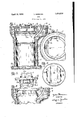
Referring to the drawings: Fig. 1 is an axial section of a closed and locked cylindrical safe "embodying my invention.` The plane of section of Fig. l is 1928. Serial No. 284,379.
indicated by lines 1-1 in Figs. 3 and 5. Fig.
2 is an axial section of the upper portion of the safe with its door removed. The plane of section of Fig. 2 is also represented by the line 1-1 in Fig. 5. Fig. 3 is an end eleva- 65 tion of the safe door turned through ninety degrees from the locking position shown in Fig. 1. The door in Fig. 8 is shown above, and in angular position to be inserted into, the safe of Fig. 2. Fig. 4 is a bottom plan 60 view ofthe safe door removed from the safe. Fig. 5 is a fragmentary plan view of the safe with its door removed.
A metal safe body is formed by a heavy steel casting 1, vpreferably of cylindrical deep 65 cup shape with aV door-way opening at its run. An outer circular door plate 2 is provided to close the door-way opening; the door-way being rabbeted or counterbored to a diameter and depth to flushly receive the door plate. A substantial shoulder la is left in the safe body below the counterbore to resist battering in the door plate.
The door plate 2 is held in tlle safe body by a cylindrical bayonet-type tongue-andgroove joint so that the door may be inserted or removed only when rotated to a particular angular position relative to the safe body. This door joint will subsequently be described more in detail.
A lock 3 is provided for locking the door against rotation in the safe body. The lock employed is preferably a conventional safedeposit-type key-operated lock 3 having a sliding locking bolt 3a which may bemoved 95 by means of keys 4 and 5 into a radial slot or y keeper at lb in the shoulder 1a of the safe body. .l
A tongue and groove'joint is provided for securing the lock 3 to the safe door. A paral 9 lelspaced pair of massive integral flanges 2a and 2a. depend from the inside face, of the door plate 2; the door plate and its flanUes being one integral solid steel casting. e lock 4is held against the door plate between 95 the flanges thereof by a heavy plane late or backing member 6, which is in turn, eld directly by the massive flanges 2a and 2a'.. The flanges are provided with opposed longitudinal slots parallel to the plate 2 at the level '10 of the back face of the lock 3. The slots form ways which receive and hold the longitudinal or side edges of the backing plate 6 (see Fig.
The plate 6 is long enough to prevent its longitudinal displacement when in the safe (see Fig. l), and is slightly tapered so that it may be jammed into its joint to prevent it from dropping out when the door is removed from the safe and also to provide a tighter joint than would otherwise be practicable.
The backing plate 6, supported behind the lock by a tongue and groove joint parallel to and partly integral with the door plate 2, practically insures against battering in of the lock. The lock abuts against the door plate, so it cannot be pried out. Displacement of the lock in directions parallel to the door plate is prevented by the flanges 2a and 2a and by the wall of the safe body; the lock being substantially as wide as the space between the flanges, and but slightly shorter than the internal diameter of the safe.
It will be observed that the lock 3 is secured to the door 2 without the necessary use of screws, rivets, pins, or like fasteners, which could be drilled out.
The main joint which holds the door in the safe will next be described. The end edges of the plate 6 are employed directly as the tongues of the main tongue-and-groove bayonet joint which holds the door in the safe; the plate 6 being appreciably longer than the minimum diameter of the safe. An annular groove of generous depth is left in the safe l body below the shoulder la. The groove is of a d1ameter to freely receive the ends of the plate 6. rl`hus the shoulder la not only prevents the door from being battered in, but` also abuts against the end edges of plate 6 to prevent the door from being pried out. The
' shoulder la is notched at 10 and similarly at the diametrically opposed position 1c', to permit insertion and removal of the door after same has been rotated through ninety degrees (i. e. to the position of Fig. 3) from its locking position (shown by Fig. l). A handle 7 of light construction is provided to facilitate handling of the door.
For residence use, the safe may be built into the wall, but in general it is preferable to embed the safe as shown, in the concrete or other floor 8, with its door-way at the floor level. A plurality of radially projecting integral anchor lugs or flanges 1d extend from the base of the safe body and are adapted to secure it in its concrete or other suitable foun- (lation.
A radial extension le of the upper portion of the safe body has a curved coin conduit formed therein at 1f leading from the surface to the interior of the safe.
A steel reinforcing band 9 is welded to the periphery of the safe at its rim.
While the aforedescribed device of my i11- vention without the use of screws, rivets, pins, or like vulnerable fasteners, is adapted to resist displacements of the lock which would permit'the safe door to be opened, yet it is recognized that such vulnerable fasteners might be superimposed thereupon forauxiliary or secondary holding power. It is therefore proper to consider devices within the purview of my invention so long as they are essentially and effectively free or independent of screws and the like-especially screws normal (i. e. perpendicular) to the safe door. The terms essentially and effectively are employed to distinguish an essential or primary use of screws or the like, from a mere superimposition or auxiliary use thereof upon an otherwise complete joint.
I have described one embodiment of my invention in det-ail, but it is emphasized that this embodiment is illustrative and not inclusive of all the forms my invention may assume. 'Certain of the objects, or certain portions or combinations of the objects of my invention may be attained with the use of less than all its advantageous features or with modifications within its purview. It is petitioned that my invention-be limited only by the claims constituting its final determination.
Il claim:
1. In combination, a safe body having a circular door-way, a circular safe door therefor, a pair of massive integral flanges on the inside face of said door, a lock abutting against the inside face of said door between said flanges; said lock being substantially as long as the diameter of said door-way and substantially as wide as the distance between said flanges; and a long backing plate secured behind said lock by said flanges; said flanges being grooved longitudinally and substantially parallel to said door to receive and hold the side edges'of said backing plate, and said doorway being slotted and grooved to form a bayonet-type joint with the end edges of said backing plate. o
2. In combination, a safe body, a safe door, a pair of integral flanges on the inside face of said door, a lock abutting against the inside face of said door between said flanges, a backing member behind said lock, a tongue and groove joint generally parallel to said door for securing said backing member to said flanges, and a second tongue and groove joint including said backing member and formed at a plurality of sides thereof for securing said door in said safe body.
3. In combination; a pair of elements one of which constitutes a door and the other of which forms a door-way therefor; a lock mounted on one of said elements and having a bolt adapted to engage the other of said elements; a backing member behind said lock; a tongue and groove joint between said backing member and an integralpart of one of said elements; and a second tongue and groove jointalso including said backing member and formed at a plurality of sides thereof for holding the door element in the door-way element.
4. In combination; a safe body having a circular door-way, a circular safe door there,- for. a pair of massive integral flanges on the inside face of said door, a lock abutting against the inside face of said. door between said ianges,'and a long backing plate secured behind said lock by saidanges; said flanges being grooved longitudinally and substantially parallel to said door to receive and hold the said edges of said backing plate, and said doorway being slotted and grooved to form a bayonet-type joint with the "end edges of said backing plate.
5. In combination, a safe body having a door-receiving cavity, a safe door therefor, and a lock mounted on said door; said lock being substantially as long as the portion of said cavity into which it projects, wherebyv to prevent its lengthwise displacement; and backing means behind said lock to resist displacement thereof by punching in the lock.
6. In combination, a safe body having a door-receiving cavity. a safe door therefor, a lock mounted on said door, and means integral with said door for preventing sidewise displacement of said lock; said lock being substantially as long as the portion of said cavity into which it projects, whereby to prevent its lengthwise displacement. A
7. A safe assembly comprising a safe body element having a circular doorway, a circular safe door element, a bayonet-type tongue and groove joint engageable by rotation of said door element in its own plane for securing the door element in the doorway, a safe lock hav;
ing a locking bolt for locking said door element against rotation; one of the aforesaid members having a keeper to receive said -locking bolt and the other of the aforesaid members having integral flanges depending inward therefrom and spacedl apart to receive said lock; and a backing member included in said bayonet-type joint and in turn joined to said piianges and securedthereby behind said lock.
8. A safe assembly comprising a safe body member having a circular doorway, a circular safe door member, a bayonet-type tongue and groove joint engageable by rotation of said door member in its own'plane for securing the door member in the doorway, a safe lock for locking said door member against rotation in said doorway, a backing member behind said lock to prevent punching in thereof, and fastening means penetrating no nearer the outer surface of said assembly than three quarters of the average wall thickness thereof for. xedly securing said backing member to said assembly;
trating no nearer the outer surface of said outer door plate than three quarters of the average thickness thereof .for securing said door plates together, a bayonet-type tongue and groove joint including said inner plate and engageable by rotation of said door .in its own plane for securing -the door in the doorway, and a safe lock nested between said door plates for locking said door against rotation.
A10. A safe assembly comprising a safe body member having a circular doorway, a circulars'afe door member, a' bayonet-type tongue and groove joint engageable by rotation of said door member in its own plane for securing the door member in the doorway, a safe lock for locking said door member against rotation, a backing member included in said bayonet-type joint and positioned behind said lock to prevent punching' in thereof, and a joint including an integral portion of one of said members for securing said backing member to said assembly; the last recited joint being of elongated oblong shape generally parallel to the outside surface of said assembly nearest thereto.
11. A safe assembly comprisingl a safe body having a circular doorway, a safe door constituted of an inner door plate and a circular outer door plate, a bayonet-type tongue and groovevv joint including said inner plate and engageable by rotation of the door in its own plane for securing said door in the doorway, a safe lock nested between said door plates for locking said door against rotation, and a joint including an integral portion of said outer door plate for securin said door plates togethers; the last recited joint being of elongated oblong shape enerall parallel to the outside surface of sai outer oor plate.
12. A safe assembly comprising a safe body having a circular doorway, a safe door constituted of an inner door plate and a circular outer door plate, a bayonet-type tongue andrgroove joint including said inner plate and engageable by rotation of the door in its own plane for securing said door in the doorway, a safe lock nested between said door plates for locking said door against rotation, and a joint including an integral portion of said outer door plate for securing said door plates together; the last recited joint having a greater area of extent generally parallel to the outer surface of said outer door plate than a screw joint of equal holding power.
13. A Lsafe assembly comprising a safe body having a circular doorway, a safe door constituted of an inner 'door plate and a circular outer door plate, a bayonet-type tongue saY ico
and groove joint including said inner plate and engageable by rotation of the door in its own plane for securing said door in the door- Way, a safe lock nested between said door plates for locking said door against rotation and a joint including an integral portion o said outer door plate for securing said door plates together; the last recited joint having' a greater linear extent generally parallel Ito the outer surface of'said outer door plate than a screw joint of e ual holding power.
- 4 HN HERMANN-
Priority Applications (1)
| Application Number | Priority Date | Filing Date | Title |
|---|---|---|---|
| US284379A US1854839A (en) | 1928-06-11 | 1928-06-11 | Safe |
Applications Claiming Priority (1)
| Application Number | Priority Date | Filing Date | Title |
|---|---|---|---|
| US284379A US1854839A (en) | 1928-06-11 | 1928-06-11 | Safe |
Publications (1)
| Publication Number | Publication Date |
|---|---|
| US1854839A true US1854839A (en) | 1932-04-19 |
Family
ID=23089989
Family Applications (1)
| Application Number | Title | Priority Date | Filing Date |
|---|---|---|---|
| US284379A Expired - Lifetime US1854839A (en) | 1928-06-11 | 1928-06-11 | Safe |
Country Status (1)
| Country | Link |
|---|---|
| US (1) | US1854839A (en) |
Cited By (9)
| Publication number | Priority date | Publication date | Assignee | Title |
|---|---|---|---|---|
| US2677338A (en) * | 1950-05-06 | 1954-05-04 | John Kelleher | Vehicle safe |
| US3417715A (en) * | 1967-05-23 | 1968-12-24 | Joseph P. Krieger | Lockable key-holding receptacle |
| US3467034A (en) * | 1967-08-02 | 1969-09-16 | Max S Kotler | Safety deposit box protector |
| US3508504A (en) * | 1968-07-25 | 1970-04-28 | Max S Kotler | Protective steel housing for locks |
| US4158337A (en) * | 1976-10-11 | 1979-06-19 | Abraham Bahry | Safe |
| US4176440A (en) * | 1977-01-12 | 1979-12-04 | Lichter Robert J | Safe, and method and apparatus for building it |
| WO1980001928A1 (en) * | 1979-03-09 | 1980-09-18 | M Sobel | Tamper resistant safe |
| US4408545A (en) * | 1977-01-12 | 1983-10-11 | Lichter Robert J | Safe, and method and apparatus for building it |
| US5060583A (en) * | 1991-02-04 | 1991-10-29 | Stinson Martin J | Floor safe |
-
1928
- 1928-06-11 US US284379A patent/US1854839A/en not_active Expired - Lifetime
Cited By (10)
| Publication number | Priority date | Publication date | Assignee | Title |
|---|---|---|---|---|
| US2677338A (en) * | 1950-05-06 | 1954-05-04 | John Kelleher | Vehicle safe |
| US3417715A (en) * | 1967-05-23 | 1968-12-24 | Joseph P. Krieger | Lockable key-holding receptacle |
| US3467034A (en) * | 1967-08-02 | 1969-09-16 | Max S Kotler | Safety deposit box protector |
| US3508504A (en) * | 1968-07-25 | 1970-04-28 | Max S Kotler | Protective steel housing for locks |
| US4158337A (en) * | 1976-10-11 | 1979-06-19 | Abraham Bahry | Safe |
| US4176440A (en) * | 1977-01-12 | 1979-12-04 | Lichter Robert J | Safe, and method and apparatus for building it |
| US4408545A (en) * | 1977-01-12 | 1983-10-11 | Lichter Robert J | Safe, and method and apparatus for building it |
| WO1980001928A1 (en) * | 1979-03-09 | 1980-09-18 | M Sobel | Tamper resistant safe |
| US4278033A (en) * | 1979-03-09 | 1981-07-14 | Bona Fide Factory Products, Inc. | Tamper resistant safe |
| US5060583A (en) * | 1991-02-04 | 1991-10-29 | Stinson Martin J | Floor safe |
Similar Documents
| Publication | Publication Date | Title |
|---|---|---|
| US3385624A (en) | Eccentric adjusting device | |
| US1854839A (en) | Safe | |
| US3477261A (en) | Apparatus for preventing access to a lock mechanism | |
| US4704880A (en) | Removable cam-lock unit and dead-bolt mechanism | |
| US9879470B2 (en) | Electrical mullion receptacle | |
| US3761119A (en) | Door protector device | |
| US3961816A (en) | Auxiliary door lock | |
| US5503088A (en) | Floor safe method and apparatus | |
| US3854764A (en) | Safety lock | |
| US2917915A (en) | Folding door lock | |
| US2935955A (en) | Wall depository for building plans and important papers | |
| US1805759A (en) | Safe | |
| US1549182A (en) | Burglarproof door latch | |
| US4278033A (en) | Tamper resistant safe | |
| US3826526A (en) | Latch bolt protector | |
| US4655145A (en) | Coin safe construction | |
| US4404916A (en) | Multiple entry closure for a safe or vault | |
| US20160168885A1 (en) | Deadbolt door locking apparatus | |
| US4404826A (en) | Keeper device for door lock | |
| US2669198A (en) | Floor safe | |
| US1967779A (en) | Closure member | |
| US1714579A (en) | Safe | |
| US770142A (en) | Strong-box for valuables. | |
| US229905A (en) | Moses moslbe | |
| US1814938A (en) | Lock |