US1854822A - Cultivator - Google Patents
Cultivator Download PDFInfo
- Publication number
- US1854822A US1854822A US284296A US28429628A US1854822A US 1854822 A US1854822 A US 1854822A US 284296 A US284296 A US 284296A US 28429628 A US28429628 A US 28429628A US 1854822 A US1854822 A US 1854822A
- Authority
- US
- United States
- Prior art keywords
- cultivator
- units
- unit
- wheel
- row
- Prior art date
- Legal status (The legal status is an assumption and is not a legal conclusion. Google has not performed a legal analysis and makes no representation as to the accuracy of the status listed.)
- Expired - Lifetime
Links
Images
Classifications
-
- A—HUMAN NECESSITIES
- A01—AGRICULTURE; FORESTRY; ANIMAL HUSBANDRY; HUNTING; TRAPPING; FISHING
- A01B—SOIL WORKING IN AGRICULTURE OR FORESTRY; PARTS, DETAILS, OR ACCESSORIES OF AGRICULTURAL MACHINES OR IMPLEMENTS, IN GENERAL
- A01B35/00—Other machines for working soil
- A01B35/02—Other machines for working soil with non-rotating tools
- A01B35/04—Other machines for working soil with non-rotating tools drawn by animal or tractor or man-power
- A01B35/08—Other machines for working soil with non-rotating tools drawn by animal or tractor or man-power with rigid tools
Definitions
- This invention relates to tillage implements, and more particularly to ⁇ tractor drawn implements intended for operation over a plurality of plant rows.
- the main object of the invention is to provide an organization for cultivating a plurality of plant rows which will permit use of existing types of implements as units inthe organization. More speciiically, the main object of the invention is to provide means whereby two or more straddle row cultivators of the horse drawn type may be connected in side by side relation and drawn as a unit by a tractor, a unitary control for the guidingV ganization embodying the novel features of construction
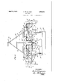
- Figure 2 is a longitudinal, vertical section of the upper part of the frame structure shown in Figure 1; 1
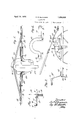
- Figure 3 is a detail view of the centralconnection between the cultivator frames as viewed from the front;
- Figure 4 is a detail of the arched connecting bar shown in Figure 3, viewed from the rear;
- Figure 5 is a detail sectional view on an enlarged scale on line 5 5 o-f Figure 1.
- the present embodiment of the invention is shown as comprising two two-row cultivators A land B, of the straddle row type and preferably of the ty e havingshiftable gangs and pivot wheels w ich aremoved in unison to guide the implement along plant rows.
- the cultivators illustrated each comprise an arched axle structure 9 supported on wheels 10mounted on swiveled standards and spindles 11 at each end which form ⁇ the vertical arms of the arched structure.
- Each standard has a forwardly extending crank arm 12 and the two standards on each unit are connected by a radius bar 13.
- tivator unit supports the usual pair of laterally shiftable arches seen at 15 (Figure 1),
- the inner side of the unit from which the wheel has been removed is supported on the axlel structure of the adjacent unit and both are supported on the single central wheel 22, vwhich is on the swiveled standard 12 of that unit.
- the supporting bracket 18 is arched to pass over the wheel 22, and its connection at 2O is preferably pivotal so that a certain amount of flexibility in a transverse plane is providedV for, so far as permitted by the natural resiliency of the structural elements now to be described.
- the cultivator units are connected by a draft frame which is common to both and which comprises forwardly converging bars 23-24, the Vrear ends of which are securedl to the frames of the respective'cultivator units, and the forward ends of which are connected to a clevis member 25 adapted for connection to the drawbar 26 of a tractor.
- Theconverging' draft bars 23-24 constitute an A- shaped frame having transverse bracing members 27---28. ⁇
- These transverse 7 meinbers are preferably connected by a central longitudinal member 29, and on the rear end of this member ( Figure 2) there is pivoted on a vertical axis at 29a a rearwardly and upwardly extending control lever 30, which terminates in a wide, heart-shaped hand bar 31.
- the lever 30 is pivoted at 3()a to an arched member 32 ( Figure 3), the arms of which extend to each cultivator unit and which is located in the saine vertical plane as the radius bars 13 which control the steering and shifting mechanism of each cultivator unit.
- the arms of the arched bar 32 are bolted to the respective radius bars 13, as at 33, and the bar 32, together with the two radius bars 13, thereby constitute a unitary structure.
- the rearwardly extending seat bars 34 belonging to each cultivator unit are made to serve as supports for posts 35 which extend upwardly a certain distance and carry an operators bench or seat 36.
- the seat bars may also serve to support a footboard 37, which may be carried in hangers 38 connected to the. seat bars.
- the combination with two straddle-row cultivator units of the pivot wheel, shiftable gang type having means on each unit for shifting its gangs and steering its wheels, of means for connecting the units side by side for operation as a single unit comprising means for supporting the inner side of one unit on the axle structure of the other, a central A-shaped draft frame having its branches secured to the respective units, an operators plat-form at the rear of the units supported on the seat posts of the two units, a lever pivoted on the draft frame and extending rearwardly towards saidplatform,
- the combination with a plurality of straddle-row cultivator units of the pivot-- wheel, shiftable gang type, of means for con necting and operating the units side by side comprising means for supporting the inner side of one unit on the axle structure of the adjacent unit, a draft frame comprising forwardly converging members connected to the respective units and connected by a crosspiece, a laterally swinging lever supported centrally on the crosspicce, and laterally extending connections between said lever and the units for steering the wheels and shifting the gangs on the units simultaneously.
Landscapes
- Life Sciences & Earth Sciences (AREA)
- Zoology (AREA)
- Engineering & Computer Science (AREA)
- Mechanical Engineering (AREA)
- Soil Sciences (AREA)
- Environmental Sciences (AREA)
- Soil Working Implements (AREA)
Description
April 19, 1932..
B. R. BENJAMIN CULTIVATOR 2 Sheets-Sheet Filed June ll, 1928 wwr zi/zior April 19, 1932. B. R. BENJAMIN CULTIVATOR Filed June ll, 1928 2 Sheets-Sheet 2 Patented Apr. 19, 1932 UNITED STATES PATENT OFFICE BERT R. BENJAMIN, F OAK PARK, ILLINOIS, ASSIGNOR TO INTERNATIONL HARVESTER COMPANY, A CORIPORATION OF NEW JERSEY CULTIVATOR Application led .Tune 11,
This invention relates to tillage implements, and more particularly to` tractor drawn implements intended for operation over a plurality of plant rows.
The main object of the invention is to provide an organization for cultivating a plurality of plant rows which will permit use of existing types of implements as units inthe organization. More speciiically,the main object of the invention is to provide means whereby two or more straddle row cultivators of the horse drawn type may be connected in side by side relation and drawn as a unit by a tractor, a unitary control for the guidingV ganization embodying the novel features of construction Figure 2 is a longitudinal, vertical section of the upper part of the frame structure shown in Figure 1; 1
Figure 3 is a detail view of the centralconnection between the cultivator frames as viewed from the front;
Figure 4 is a detail of the arched connecting bar shown in Figure 3, viewed from the rear; and
Figure 5 is a detail sectional view on an enlarged scale on line 5 5 o-f Figure 1.
The present embodiment of the invention is shown as comprising two two-row cultivators A land B, of the straddle row type and preferably of the ty e havingshiftable gangs and pivot wheels w ich aremoved in unison to guide the implement along plant rows. The cultivators illustrated each comprise an arched axle structure 9 supported on wheels 10mounted on swiveled standards and spindles 11 at each end which form `the vertical arms of the arched structure. Each standard has a forwardly extending crank arm 12 and the two standards on each unit are connected by a radius bar 13. The frame 14 of the cul- 1928. Serial No. 284,296.
tivator unit supports the usual pair of laterally shiftable arches seen at 15 (Figure 1),
both of which are connected through linkage 16 to the radius bar 13. The usual pairs of cultivator beams 17 are connected to the arms of the arches 15 and shift in unison therewith. The two-row cultivator structure briefly described above is that of the patent to Dennis 1,667,37 4, April 24, 1928, where more detailed description of the structure will be found.
Inthe practice of the present invention, two such cultivator units as described are placed side by side with the axle structures of the respective units in alignment. The wheel and bearing spindle at the inner side of one of the units is removed, as best shown in Figure 3, and the two axle structures are connected by Van arched bracket member 18. This member 18 is preferably pivoted on the axle structure of the cultivator unit from which the inner wheel has been removed, as by means of a horizontal clamp plate 19 bolted on the axle'structure and having a projecting end to which the arched bracket 18 is connected by a pivotbolt, as at 20. The opposite end of the bracket 18 is bolted to the axle structure of the other unit, as at 21. By this construct-ionV the inner side of the unit from which the wheel has been removed is supported on the axlel structure of the adjacent unit and both are supported on the single central wheel 22, vwhich is on the swiveled standard 12 of that unit. The supporting bracket 18 is arched to pass over the wheel 22, and its connection at 2O is preferably pivotal so that a certain amount of flexibility in a transverse plane is providedV for, so far as permitted by the natural resiliency of the structural elements now to be described. The cultivator units are connected by a draft frame which is common to both and which comprises forwardly converging bars 23-24, the Vrear ends of which are securedl to the frames of the respective'cultivator units, and the forward ends of which are connected to a clevis member 25 adapted for connection to the drawbar 26 of a tractor. Theconverging' draft bars 23-24 constitute an A- shaped frame having transverse bracing members 27---28.` These transverse 7 meinbers are preferably connected by a central longitudinal member 29, and on the rear end of this member (Figure 2) there is pivoted on a vertical axis at 29a a rearwardly and upwardly extending control lever 30, which terminates in a wide, heart-shaped hand bar 31. Intermediate its ends the lever 30 is pivoted at 3()a to an arched member 32 (Figure 3), the arms of which extend to each cultivator unit and which is located in the saine vertical plane as the radius bars 13 which control the steering and shifting mechanism of each cultivator unit. The arms of the arched bar 32 are bolted to the respective radius bars 13, as at 33, and the bar 32, together with the two radius bars 13, thereby constitute a unitary structure. The rearwardly extending seat bars 34 belonging to each cultivator unit are made to serve as supports for posts 35 which extend upwardly a certain distance and carry an operators bench or seat 36. The seat bars may also serve to support a footboard 37, which may be carried in hangers 38 connected to the. seat bars.
Vith the organization above described, it will be seen that two cultivator units of standard type may be joined to form a multiple row cultivator,-in this instance, a four-row machine. It will also be seen that a single operator seated on the bench 36 may readily observe the operation of the combined units and control the gang shifting and wheel steering mechanisms of both cultivator units simultaneously through the lever 30 and its connections, the handle 31 of which is within easy reach of the operator irrespective of his position on the bench 36.
There has accordingly been provided a simple and eficient structure by the use of which two or more cultivator units may be united into one machine organization for use behind a tractor, with the added eliiciency and other advantages obtainable through the use of two or more ordinary units at once, and, while the above structure exemplifies the preferred embodiment yof the invention, modifications thereof are obviously possible within the scope of the following claims.
What is claimed is:
1. In a multiple row tractor cultivator organization, the combination with two straddle-row cultivator units of the pivot wheel, shiftable gang type having means on each unit for shifting its gangs and steering its wheels, of means for connecting the units side by side for operation as a single unit comprising means for supporting the inner side of one unit on the axle structure of the other, a central A-shaped draft frame having its branches secured to the respective units, an operators plat-form at the rear of the units supported on the seat posts of the two units, a lever pivoted on the draft frame and extending rearwardly towards saidplatform,
' and connections between said lever and the shifting means for the wheels and gangs of the units.
2. In a multiple row tractor cultivator organization, the combination with a plurality of straddle-row cultivator units of the pivot-- wheel, shiftable gang type, of means for con necting and operating the units side by side comprising means for supporting the inner side of one unit on the axle structure of the adjacent unit, a draft frame comprising forwardly converging members connected to the respective units and connected by a crosspiece, a laterally swinging lever supported centrally on the crosspicce, and laterally extending connections between said lever and the units for steering the wheels and shifting the gangs on the units simultaneously.
3. In a multiple row tractor cultivator organization, the combination with a plurality of straddle-row cultivator units of the pivot wheel, shiftable gang type having means on each unit for shiftingits gangs and steering its wheels, of means for connecting and operating the units side by side comprising a draft frame having members connected to each unit and extending forwardly, and means for steering the wheels and shifting the gangs on the units simultaneously comprising a manually operable control device mounted centrally on the draft frame and connected to the shifting means for the gangs and wheel supports of each unit.
In testimony whereof I afx my signature.
BERT R. BENJAMIN.
Priority Applications (1)
| Application Number | Priority Date | Filing Date | Title |
|---|---|---|---|
| US284296A US1854822A (en) | 1928-06-11 | 1928-06-11 | Cultivator |
Applications Claiming Priority (1)
| Application Number | Priority Date | Filing Date | Title |
|---|---|---|---|
| US284296A US1854822A (en) | 1928-06-11 | 1928-06-11 | Cultivator |
Publications (1)
| Publication Number | Publication Date |
|---|---|
| US1854822A true US1854822A (en) | 1932-04-19 |
Family
ID=23089641
Family Applications (1)
| Application Number | Title | Priority Date | Filing Date |
|---|---|---|---|
| US284296A Expired - Lifetime US1854822A (en) | 1928-06-11 | 1928-06-11 | Cultivator |
Country Status (1)
| Country | Link |
|---|---|
| US (1) | US1854822A (en) |
Cited By (1)
| Publication number | Priority date | Publication date | Assignee | Title |
|---|---|---|---|---|
| US2996128A (en) * | 1957-09-03 | 1961-08-15 | Massey Ferguson Inc | Tractor drawn implements |
-
1928
- 1928-06-11 US US284296A patent/US1854822A/en not_active Expired - Lifetime
Cited By (1)
| Publication number | Priority date | Publication date | Assignee | Title |
|---|---|---|---|---|
| US2996128A (en) * | 1957-09-03 | 1961-08-15 | Massey Ferguson Inc | Tractor drawn implements |
Similar Documents
| Publication | Publication Date | Title |
|---|---|---|
| US3225839A (en) | Mechanism for adjusting tool and ground support relative to supporting frame | |
| US1854822A (en) | Cultivator | |
| US1663249A (en) | Tractor cultivator | |
| US1746606A (en) | Tractor drawbar cultivator | |
| US1760128A (en) | Farm-implement attachment for tractors | |
| US2172983A (en) | Implement lifting mechanism | |
| US1831990A (en) | Cultivator attachment for tractors | |
| US1648639A (en) | Tractor-drawn cultivator | |
| US1776242A (en) | Motor cultivator attachment | |
| US1718773A (en) | Tractor cultivator | |
| US2362695A (en) | Agricultural implement | |
| US2053618A (en) | Agricultural implement | |
| US1854879A (en) | Tractor cultivator | |
| US1844560A (en) | Rotary hoe | |
| US1418262A (en) | Hand-steered, wheeled, convertible cultivator and planter | |
| US1967321A (en) | Tractor lister cultivator | |
| US1613079A (en) | Cultivator | |
| US1819679A (en) | Tractor lister attachment | |
| US2245884A (en) | Cultivator | |
| US396627A (en) | Cultivator | |
| US435831A (en) | Combined cultivator and seeder | |
| US2228558A (en) | Portable implement support | |
| US637190A (en) | Agricultural implement. | |
| US1548622A (en) | Cross-plowing cultivator | |
| US1928321A (en) | Lister cultivator |