US1854879A - Tractor cultivator - Google Patents
Tractor cultivator Download PDFInfo
- Publication number
- US1854879A US1854879A US483164A US48316430A US1854879A US 1854879 A US1854879 A US 1854879A US 483164 A US483164 A US 483164A US 48316430 A US48316430 A US 48316430A US 1854879 A US1854879 A US 1854879A
- Authority
- US
- United States
- Prior art keywords
- tractor
- steering
- dragbars
- secured
- cultivator
- Prior art date
- Legal status (The legal status is an assumption and is not a legal conclusion. Google has not performed a legal analysis and makes no representation as to the accuracy of the status listed.)
- Expired - Lifetime
Links
Images


Classifications
-
- A—HUMAN NECESSITIES
- A01—AGRICULTURE; FORESTRY; ANIMAL HUSBANDRY; HUNTING; TRAPPING; FISHING
- A01B—SOIL WORKING IN AGRICULTURE OR FORESTRY; PARTS, DETAILS, OR ACCESSORIES OF AGRICULTURAL MACHINES OR IMPLEMENTS, IN GENERAL
- A01B35/00—Other machines for working soil
- A01B35/02—Other machines for working soil with non-rotating tools
- A01B35/10—Other machines for working soil with non-rotating tools mounted on tractors
- A01B35/12—Other machines for working soil with non-rotating tools mounted on tractors with spring tools or with resiliently-or flexibly-attached rigid tools
Definitions
- B. R. BENJAMIN TRACTOR CULTIVATOR Filed Sept. 20, 1930 3 SheetsSheet l April 19, 1932.
- B R. BENJAMIN TRACTOR CULTIVATOR Filed Sept. 20, 1950 3 Sheets-Sheet 2 April 19, 1932.
- B. R. BENJAMIN TRACTOR CULTIVATOR Filed Sept. 20, 1950 3 SheetsSheet 3 fierj amin Patented Apr. 19, 1932 UNITED STATES PATENT oFncE BERT R.
- the present invention relates to tractor cultivators and in particular to cultivator attachments of the type carried on the forward portion of the tractor.
- the main object of the invention is to provide a row crop cultivating attachment of simple construction, which can be readily mounted on tractors and which will embody means for imparting guiding movements to g 10 its tillage tools through operating connecstruction in which the invention resides are described in detail in the following specification and illustrated in the accompanying drawings where:
- Figure 1 is a plan. view of a tractor cultivator embodying the invention
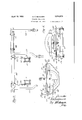
- Figure 2 is a side elevation of the same
- Figure 3 is a side View of latch mechanism on the front end of the tractor, certain parts beingin section;
- Figure 4 is an enlarged view of the parts shown in Figure 3;
- Figure 5- is aplan View of the structure shown in Figure 3;
- Figure 6 is a front view of the same Figure 7 is an enlarged detail view of the parts of the structure shown in Figure 5, as
- Figure -8 is an enlarged detail view of a gang shifting member and parts associated therewith as viewed on line 8-8 of F igure 1.
- the invention has been illustrated as embodied in a cultivator attachment mounted on a row crop tractor of the type having an extended rear axle structure 10 adapted to span the space of two plant rows of such crops as corn or cotton.
- the axle supports a narrow, forwardly extending body composed of side sills 11 carrying the usual power plant, the forward ends of the side sills being supported on a cross-head 12 in which there is journaled the upright standard 13 of a steering truck 14:.
- the upper end of the standard 13 is journaled in a casting or bracket 15, which supports the forward end of a steering shaft 16 connected. to the steering standard by suitable gears 17
- the steering shaft 16 is equipped with the usual hand wheel 18 located at the operators station on the rear of the tractor.
- the cultivator attachment constituting the novel structure adapted for combination with the tractor just described comprises a transversely extended draft member or supporting shaft 19' forming the main member of a supporting frame which is fixedly secured to the front end of the tractor.
- This frame preferably comprises a vertical, arched member 20, the arms of which are secured to side brackets on the tractor by means of bolts 21 ( Figure 2).
- the arched member has secured to its arms above the point of attachment of the bolts 21, a forwardly extending yoke or arched member 22.
- the transverse draft member 19 extends through the sides of the yoke 22, as shown in Figures 1 and 3, and is secured in position by U-bolts 23 passing through the arms of the upwardly arched member 20.
- This structure provides a very rigid supporting or draft frame capable of withstanding the strains received from the implements connected thereto.
- the main transverse draft member 19 projects beyond each side of. the body of the. tractor and each projecting end has mounted on it a sleeve 27, which is'free to oscillate thereon.
- Each sleeve 27 carries two sleeves 28 to which the dragbars 29" are connected by pivot bolts 30'.
- Each dragbar carries suitable tillage tools.
- the tools are illustrated as comprising an angularly adjustable bar 31 on the ends of which spring standards 32 of cultivator shovels are adjustably mounted.
- Each sleeve 27 is provided with a fixed, upstanding, crank arm 33 connected by a rearwardly extending adjusting rod 34 to a hand lever 35 mounted on the rear axle structure of the tractor.
- Each lever 35 is provided with the ..usual locking rack, and swinging of either lever will oscillate the corresponding sleeve 27 and act to raise the dragbars 29 also.
- each adjusting rod 34 is provided near its forward end with a bracket 36 clamped thereon.
- This bracket includes a cross member 37, the ends of which are apertured to receive the upper ends of lifting rods 38, which are loosely connected to the rear ends of the respective dragbars.
- the usual coil springs 39 are carried by the rods and confined between collars 40 and the under sideof the cross member 37.
- each dragbar is formed with a vertical aperture, through which there extends the depending ends of angular members 41, 42, preferably formed of flat bars the upper ends of which are overlapped, forming a jockey arch.
- the two arches are connected by a cross member 43 extending across the tractor body above the side sill members 11, as best seen in Figure 8.
- the horizontal portions of the members 41 and 42 of each jockey arch are secured to the projecting ends of the cross member 43 by clamps 44, which permit the arch to be spread or contracted, as desired.
- a roc-kshaft 45 which is preferably duplicated on each side of the tractor. supported at its rear end in a journal bracket 46 secured to the side sill 11 and, at its front end, is supported in an opening in the arch member 20 through which it extends.
- a forward end of each rockshaft 45 is formed with an upwardly extending crank arm 47, and a similar upwardly extending crank arm 48 is formed 011 or secured to the rear end of each shaft.
- the forward crank arms 47 ( Figures 5 and 6) are connected by a cross bar 49, which is pivotally connected to the ends of the crank arms.
- This bar 49 has secured to it a horizontal, arched bar 50, the arms of Each shaft 45 is to a point just above the arched bar 50 and passes beneath the plate 51, to which it is centrally connected as by a pivot bolt 53.
- the tractor standard 1.3 is provided with a forwardly projecting, fixed arm 54, which necessarily swings when the standard 13 is turned to effect steering movements of the tractor.
- the loose arm 52 is provided at its under side with a depending bracket 56 ( Figure 4), which carries a locking pawl 57 on a pivot at its lower end, which pawl is normally spring pressed in a direction to engage a suitable notch in the end of the fixed arm 54.
- the pawl 57 may be retracted when desired, through actuation of a lever 58 which is mounted on a vertical pivot on the arched bar 50.
- One end of this lever is connected by a link 59 to the pawl 57 and the other end of the lever is connected to a link or cable 60, which in turn is connected to a trip pedal 61 adjacent the operators station on the tractor.
- the rear cranks 48 on the rockshafts 45 are pivotally connected by means of brackets 62 to the intermediate portion of the cross member 43, as best seen in Figure 8.
- the structure described is a simple, strong and easily mounted cultivator attachment for tractors, which may be equipped with tillage tools of any desired type and which may be readily connected to the steering mechanism or other control means on the tractor when lateral shifting or dodging of the tools is desired.
- a tractor comprising rear wheels and a central forward steering truck having a vertical pivot and means for steering the truck, of cultivating tools at each side of the truck and forward of the rear wheels, a longitudinally extending shaft mounted in bearings on'each side of the tractor, means for oscillating said shafts by actuation of the steering means, a crossbar connected to the rear ends of said shafts and shiftable laterally upon oscillation of the shafts, and depending members on the crossbar having engagement with the cultivating tools.
- a tractor comprising rear wheels and a central forward steering truck having a vertical pivot and means for steering the truck, of cultivating tools at each side of the truck and forward of the rear wheels, a longitudinally extending shaft mounted in bearings on each side of the tractor, a link connecting the front ends of said shafts for joint oscillation, latch controlled means for connecting said link to the steering truck for transverse movement whereby the shafts will be oscillated, and means for causing lateral movement of the cultivating tools upon oscillation of said shafts.
- a cultivator attachment for tractors comprising an extended draft member, means on said member for mounting it forwardly on a tractor with its end portions projecting at each side of the tractor body, dragbars pivoted on the end portions of the draft member to swing laterally, tillage tools on the dragbars, a rockshaft journaled at its forward end on the draft member and having means at its rear end for mounting it on a tractor, a cross-member connected to the rear end of said rockshaft to receive movement therefrom, connections between said crossmember and the dragbars, and means on the rockshaft adapted for connection to a manually movable part of the tractor.
Landscapes
- Life Sciences & Earth Sciences (AREA)
- Engineering & Computer Science (AREA)
- Mechanical Engineering (AREA)
- Soil Sciences (AREA)
- Environmental Sciences (AREA)
- Soil Working Implements (AREA)
- Agricultural Machines (AREA)
Description
April 19, 1932. B. R. BENJAMIN TRACTOR CULTIVATOR Filed Sept. 20, 1930 3 SheetsSheet l April 19, 1932. B R. BENJAMIN TRACTOR CULTIVATOR Filed Sept. 20, 1950 3 Sheets-Sheet 2 April 19, 1932. B. R. BENJAMIN TRACTOR CULTIVATOR Filed Sept. 20, 1950 3 SheetsSheet 3 fierj amin Patented Apr. 19, 1932 UNITED STATES PATENT oFncE BERT R. BENJAMIN, OF OAK PARK, ILLINOIS, ASSIGNOR TO INTERNATIONAL HAR- VESIER COMPANY, A GORPORATION OF NEW JERSEY TRACTOR CULTIVATOR Application filed September 20, 1930. Serial No. 483,164.
The present invention relates to tractor cultivators and in particular to cultivator attachments of the type carried on the forward portion of the tractor.
The main object of the invention is to provide a row crop cultivating attachment of simple construction, which can be readily mounted on tractors and which will embody means for imparting guiding movements to g 10 its tillage tools through operating connecstruction in which the invention resides are described in detail in the following specification and illustrated in the accompanying drawings where:
Figure 1 is a plan. view of a tractor cultivator embodying the invention;
Figure 2 is a side elevation of the same;
Figure 3 is a side View of latch mechanism on the front end of the tractor, certain parts beingin section;
Figure 4 is an enlarged view of the parts shown in Figure 3;
Figure 5- is aplan View of the structure shown in Figure 3;
Figure 6 is a front view of the same Figure 7 is an enlarged detail view of the parts of the structure shown in Figure 5, as
viewed on line 77 of Figure 5 and,
Figure -8 is an enlarged detail view of a gang shifting member and parts associated therewith as viewed on line 8-8 of F igure 1.
In the present instance, the invention has been illustrated as embodied in a cultivator attachment mounted on a row crop tractor of the type having an extended rear axle structure 10 adapted to span the space of two plant rows of such crops as corn or cotton. The axle supports a narrow, forwardly extending body composed of side sills 11 carrying the usual power plant, the forward ends of the side sills being supported on a cross-head 12 in which there is journaled the upright standard 13 of a steering truck 14:. The upper end of the standard 13 is journaled in a casting or bracket 15, which supports the forward end of a steering shaft 16 connected. to the steering standard by suitable gears 17 The steering shaft 16 is equipped with the usual hand wheel 18 located at the operators station on the rear of the tractor.
The cultivator attachment constituting the novel structure adapted for combination with the tractor just described comprises a transversely extended draft member or supporting shaft 19' forming the main member of a supporting frame which is fixedly secured to the front end of the tractor. This frame preferably comprises a vertical, arched member 20, the arms of which are secured to side brackets on the tractor by means of bolts 21 (Figure 2). The arched member has secured to its arms above the point of attachment of the bolts 21, a forwardly extending yoke or arched member 22. The transverse draft member 19 extends through the sides of the yoke 22, as shown in Figures 1 and 3, and is secured in position by U-bolts 23 passing through the arms of the upwardly arched member 20. An upwardly arched truss bar 2411s secured to the ends of the draft member 19 and to the upper portion of the vertical, arched member 20', and a second horizontally arched truss bar 25 is also secured to the ends of the draft member 19' and to the forward portion of the yoke 22, as shown in Figure 1. This structure provides a very rigid supporting or draft frame capable of withstanding the strains received from the implements connected thereto. The main transverse draft member 19 projects beyond each side of. the body of the. tractor and each projecting end has mounted on it a sleeve 27, which is'free to oscillate thereon. Each sleeve 27 carries two sleeves 28 to which the dragbars 29" are connected by pivot bolts 30'. Each dragbar carries suitable tillage tools. In this instance, the tools are illustrated as comprising an angularly adjustable bar 31 on the ends of which spring standards 32 of cultivator shovels are adjustably mounted. Each sleeve 27 is provided with a fixed, upstanding, crank arm 33 connected by a rearwardly extending adjusting rod 34 to a hand lever 35 mounted on the rear axle structure of the tractor. Each lever 35 is provided with the ..usual locking rack, and swinging of either lever will oscillate the corresponding sleeve 27 and act to raise the dragbars 29 also. To further assist the lifting operation and also apply yielding pressure to the rear end of the dragbars, each adjusting rod 34 is provided near its forward end with a bracket 36 clamped thereon. This bracket includes a cross member 37, the ends of which are apertured to receive the upper ends of lifting rods 38, which are loosely connected to the rear ends of the respective dragbars. The usual coil springs 39 are carried by the rods and confined between collars 40 and the under sideof the cross member 37.
To maintain each pair of dragbars 29 and the tools carried thereby at a desired spaced relation, the rear end of each dragbar is formed with a vertical aperture, through which there extends the depending ends of angular members 41, 42, preferably formed of flat bars the upper ends of which are overlapped, forming a jockey arch. The two arches are connected by a cross member 43 extending across the tractor body above the side sill members 11, as best seen in Figure 8. The horizontal portions of the members 41 and 42 of each jockey arch are secured to the projecting ends of the cross member 43 by clamps 44, which permit the arch to be spread or contracted, as desired.
In order to provide lateral shifting or dodging movement to the dragbars for row following purposes, there has been provided a roc-kshaft 45 which is preferably duplicated on each side of the tractor. supported at its rear end in a journal bracket 46 secured to the side sill 11 and, at its front end, is supported in an opening in the arch member 20 through which it extends. A forward end of each rockshaft 45 is formed with an upwardly extending crank arm 47, and a similar upwardly extending crank arm 48 is formed 011 or secured to the rear end of each shaft. The forward crank arms 47 (Figures 5 and 6) are connected by a cross bar 49, which is pivotally connected to the ends of the crank arms. This bar 49 has secured to it a horizontal, arched bar 50, the arms of Each shaft 45 is to a point just above the arched bar 50 and passes beneath the plate 51, to which it is centrally connected as by a pivot bolt 53. Immediately below the loose or freely rotatable arm 52, the tractor standard 1.3 is provided with a forwardly projecting, fixed arm 54, which necessarily swings when the standard 13 is turned to effect steering movements of the tractor. In order to connect the two arms 52 and 54 at will and thereby cause oscillation of the rockshafts 45, the loose arm 52 is provided at its under side with a depending bracket 56 (Figure 4), which carries a locking pawl 57 on a pivot at its lower end, which pawl is normally spring pressed in a direction to engage a suitable notch in the end of the fixed arm 54. The pawl 57 may be retracted when desired, through actuation of a lever 58 which is mounted on a vertical pivot on the arched bar 50. One end of this lever is connected by a link 59 to the pawl 57 and the other end of the lever is connected to a link or cable 60, which in turn is connected to a trip pedal 61 adjacent the operators station on the tractor. The rear cranks 48 on the rockshafts 45 are pivotally connected by means of brackets 62 to the intermediate portion of the cross member 43, as best seen in Figure 8.
It will be understood from the foregoing description that operation of the steering gear of the tractor to effect steering movements of the truck 14 will cause the rigid arm 54 to swing in a horizontal are. If the pawl 57 is in engagement with the notch in the end of arm 54, the free arm 52 will be carried with it and also the cross bar 49. Transverse movement of the crossbar will rock the two shafts 45 simultaneously, thereby causing the cross member 43 and the jockey arches carried by each end thereof to be shifted laterally in the direction of steering movement of the tractor. As the depending ends of the jockey arches are engaged in the apertures in the rear ends of the dragbars 29, all of the dragbars will be collectively shifted on their pivots 30 in a corresponding manner but lifting and lowering of the dragbars will not be interfered with. A quickv and easily effected dodging movement is, therefore, imparted to the tillage tools. The structure described is a simple, strong and easily mounted cultivator attachment for tractors, which may be equipped with tillage tools of any desired type and which may be readily connected to the steering mechanism or other control means on the tractor when lateral shifting or dodging of the tools is desired.
lVhile a preferred embodiment of the invention has been described in detail, it will be obvious that material modifications in details of structure may be used without departing from the scope of the invention as defined in the following claims.
What is claimed is:
l. The combination with a tractor having dirigible front wheels and means for steering said wheels, of a transverse draft member secured at its middle to the forward portion of the tractor andprojecting beyond each side thereof, cultivating tools at each side of the tractor comprising a pair of dragbars pivoted to each end of the draft memher for movement laterally, spacing means connecting the rear ends of the dragbars of each pair, a cross bar mounted on the tractor for lateral shifting movement and connected to the spacing means for each pair of dragbars, and means for shifting the crossbar by actuation of the steering means.
2. The combination with a tractor having dirigible front wheels and means for steering said wheels, of a transverse draft member secured at its middle to the forward portion of the tractor and projecting beyond each side thereof, cultivating tools at each side of the tractor comprising a pair of drag bars, a sleeve ournaled for rotation on each end of the draft member, a pair of brackets clamped on each sleeve on which the forward ends of the dragbars are pivoted for movement laterally, means for rotating said sleeves to raise and lower the dragbars, spreader arches for holding the rear ends of each pair of dragbars in spaced relation, a crossbar mounted on the tractor for lateral shifting movement and secured to the spreader arches, and means for shifting the crossbar by actuation of the steering means.
3. The combination with a tractor comprising rear wheels and a central forward steering truck having a vertical pivot and means for steering the truck, of cultivating tools at each side of the truck and forward of the rear wheels, a longitudinally extending shaft mounted in bearings on each side of the tractor, means for oscillating said shafts by actuation of the steering means, and means for causing lateral movement of the cultivating tools upon oscillation of said shaft-s.
4. The combination with a tractor comprising rear wheels and a central forward steering truck having a vertical pivot and means for steering the truck, of cultivating tools at each side of the truck and forward of the rear wheels, a longitudinally extending shaft mounted in bearings on'each side of the tractor, means for oscillating said shafts by actuation of the steering means, a crossbar connected to the rear ends of said shafts and shiftable laterally upon oscillation of the shafts, and depending members on the crossbar having engagement with the cultivating tools.
5. The combination with a tractor comprising rear wheels and a central forward steering truck having a vertical pivot and means for steering the truck, of cultivating tools at each side of the truck and forward of the rear wheels, a longitudinally extending shaft mounted in bearings on each side of the tractor, a link connecting the front ends of said shafts for joint oscillation, latch controlled means for connecting said link to the steering truck for transverse movement whereby the shafts will be oscillated, and means for causing lateral movement of the cultivating tools upon oscillation of said shafts.
6. A cultivator attachment for tractors comprising an extended draft member, means on said member for mounting it forwardly on a tractor with its end portions projecting at each side of the tractor body, dragbars pivoted on the end portions of the draft member to swing laterally, tillage tools on the dragbars, a rockshaft journaled at its forward end on the draft member and having means at its rear end for mounting it on a tractor, a cross-member connected to the rear end of said rockshaft to receive movement therefrom, connections between said crossmember and the dragbars, and means on the rockshaft adapted for connection to a manually movable part of the tractor.
In testimony whereof I aflix my signature.
BERT R. BENJAMIN.
Priority Applications (1)
| Application Number | Priority Date | Filing Date | Title |
|---|---|---|---|
| US483164A US1854879A (en) | 1930-09-20 | 1930-09-20 | Tractor cultivator |
Applications Claiming Priority (1)
| Application Number | Priority Date | Filing Date | Title |
|---|---|---|---|
| US483164A US1854879A (en) | 1930-09-20 | 1930-09-20 | Tractor cultivator |
Publications (1)
| Publication Number | Publication Date |
|---|---|
| US1854879A true US1854879A (en) | 1932-04-19 |
Family
ID=23918925
Family Applications (1)
| Application Number | Title | Priority Date | Filing Date |
|---|---|---|---|
| US483164A Expired - Lifetime US1854879A (en) | 1930-09-20 | 1930-09-20 | Tractor cultivator |
Country Status (1)
| Country | Link |
|---|---|
| US (1) | US1854879A (en) |
-
1930
- 1930-09-20 US US483164A patent/US1854879A/en not_active Expired - Lifetime
Similar Documents
| Publication | Publication Date | Title |
|---|---|---|
| US1932112A (en) | Rear cultivator attachment for tractors | |
| US1854879A (en) | Tractor cultivator | |
| US2005568A (en) | Tractor mounted cultivator | |
| US1936749A (en) | Tractor cultivator | |
| US1760128A (en) | Farm-implement attachment for tractors | |
| US1776242A (en) | Motor cultivator attachment | |
| US1854834A (en) | Tractor implement attachment | |
| US2144347A (en) | Lister | |
| US2172983A (en) | Implement lifting mechanism | |
| US1889486A (en) | Agricultural machine | |
| US2224800A (en) | Cultivator attachment | |
| US1946664A (en) | Tractor cultivator | |
| US2136640A (en) | Adjusting mechanism for tractor implements | |
| US1940992A (en) | Implement attachment for tractors | |
| US1946402A (en) | Cultivator | |
| US1718773A (en) | Tractor cultivator | |
| US2072139A (en) | Cultivator attachment for tractors | |
| US1819624A (en) | Tractor cultivator | |
| US1418262A (en) | Hand-steered, wheeled, convertible cultivator and planter | |
| US1105450A (en) | Three-row wheel corn-cultivator. | |
| US1738510A (en) | Agricultural implement | |
| US1819679A (en) | Tractor lister attachment | |
| US1814815A (en) | Agricultural implement | |
| US1667367A (en) | Cultivator | |
| US2129746A (en) | Tractor cultivator |