US1854761A - Method of and apparatus for agitating - Google Patents
Method of and apparatus for agitating Download PDFInfo
- Publication number
- US1854761A US1854761A US344971A US34497129A US1854761A US 1854761 A US1854761 A US 1854761A US 344971 A US344971 A US 344971A US 34497129 A US34497129 A US 34497129A US 1854761 A US1854761 A US 1854761A
- Authority
- US
- United States
- Prior art keywords
- container
- guide
- liquid
- impeller
- tubular guide
- Prior art date
- Legal status (The legal status is an assumption and is not a legal conclusion. Google has not performed a legal analysis and makes no representation as to the accuracy of the status listed.)
- Expired - Lifetime
Links
- 238000000034 method Methods 0.000 title description 5
- 239000007788 liquid Substances 0.000 description 20
- 239000000463 material Substances 0.000 description 6
- 230000002093 peripheral effect Effects 0.000 description 6
- 239000000203 mixture Substances 0.000 description 4
- 239000000470 constituent Substances 0.000 description 3
- 239000012530 fluid Substances 0.000 description 3
- 238000000926 separation method Methods 0.000 description 3
- 238000010276 construction Methods 0.000 description 2
- 230000000750 progressive effect Effects 0.000 description 2
- 230000001105 regulatory effect Effects 0.000 description 2
- 238000009991 scouring Methods 0.000 description 2
- 241000239290 Araneae Species 0.000 description 1
- 240000002989 Euphorbia neriifolia Species 0.000 description 1
- 238000013019 agitation Methods 0.000 description 1
- 239000004568 cement Substances 0.000 description 1
- 239000011344 liquid material Substances 0.000 description 1
- 239000000314 lubricant Substances 0.000 description 1
- 239000003973 paint Substances 0.000 description 1
- 239000002002 slurry Substances 0.000 description 1
- 239000007858 starting material Substances 0.000 description 1
- 239000000725 suspension Substances 0.000 description 1
- 238000010408 sweeping Methods 0.000 description 1
Images
Classifications
-
- B—PERFORMING OPERATIONS; TRANSPORTING
- B01—PHYSICAL OR CHEMICAL PROCESSES OR APPARATUS IN GENERAL
- B01F—MIXING, e.g. DISSOLVING, EMULSIFYING OR DISPERSING
- B01F27/00—Mixers with rotary stirring devices in fixed receptacles; Kneaders
- B01F27/80—Mixers with rotary stirring devices in fixed receptacles; Kneaders with stirrers rotating about a substantially vertical axis
- B01F27/91—Mixers with rotary stirring devices in fixed receptacles; Kneaders with stirrers rotating about a substantially vertical axis with propellers
-
- B—PERFORMING OPERATIONS; TRANSPORTING
- B01—PHYSICAL OR CHEMICAL PROCESSES OR APPARATUS IN GENERAL
- B01F—MIXING, e.g. DISSOLVING, EMULSIFYING OR DISPERSING
- B01F27/00—Mixers with rotary stirring devices in fixed receptacles; Kneaders
- B01F27/05—Stirrers
- B01F27/11—Stirrers characterised by the configuration of the stirrers
- B01F27/15—Stirrers with tubes for guiding the material
Definitions
- Fig. 1 is an axial sectional view of an embodiment of the invention; and Figs. 2 and 3 are sectional'details. Y Y
- a container 1 and an impelling means, advantageously a screw propeller S, carried by a shaft 3 and driven from any suitable source of power.
- the container may be of shape and dimensions required by particular circumstances, ordinarily a cylindrical shape being most desira-t ble.
- the impeller is mounted in the lower portion of the container, and preferably the blades 2 are regulable as to pitch, this being provided by any suitable means, as for instance journalled stems 2a and set screws 9]) for tightening against the respective bladestems to hold them in desired pitch position.
- a current guide in the form of a tubular shell
- the cross section of which may be of noncircular form, but which ordinarily is circular.
- Such current guide is regulable moreover as to its height in the container, whereby I it may be readily adapted to various amounts of liquid material under treatment.
- the guide is of a telescopic character, being made up of any preferred number of sections 4a, 46, it, these sections nesting closely so as to favor adju'stability without material space requirement.
- the section adjacent the impeller is held in fixed position, as by support rods or standards 5, and the sections 46, thence are telscopiv cally mounted thereon, the section 40a for instance being slightly flanged outwardly at its upper end, while the section 46 is correspondingly flanged inwardly at its lower end.
- Means for raising and lowering v the sections are provided, for instance cables 6 attached to the upper section, and wound on drums 7 operated by shaft 8. The latter may be actuated by a hand wheel 9 through suitable gearing.
- lar guide may be extended to whatever length may be desired in view of the requirements at any given time, and the upper edge of the guide may be maintained at all times at a In this manner, the tubusuitable distance below the surface of the liquid so as 'to allow of circulation.
- a tell-tale or indicator 10 may be secured to the cable at a suitable distance above the top of the upper section of the tubular guide to facilitate maintaining proper submergence depth, it being then merely necessary to regulate the cable so thatthe indicator 10 is at the surface of the liquid.
- the tubular guide divides the liquid mass undergoing treatment into two columns, an inner or central column and an outer or peripheral column, the tubular guide making a division therebetween; and accordingly the liquid mass may circulate efi'ectively, as set in motion by the agitating impeller.
- the cross sectional areas within and without the tubular guide are preferably substantially equal, this being readily attained by dimensioning the tubular guide in accordance with the mathematical requirements of the areas of the concentric circle-s. In this manner, the area for circulatory action is equal inside and out with respect to the tubular guide, and an even circulation is favored.
- the floor of the container is preferably recurved, as at 12,'the sweep of liquid thus being caused to exert ascouring action upon the bottom; and with absence of eddy currents in dead corner spaces, thedirect force of the current stream is made available, and consequently deposited materials are capable of being readily loosened up and put into circulation.
- baffle plates 13- may be suitable positioned, a convenient mounting involving for instance channel forms 14 secured to the container walls, and witha baflie plate correspondingly flanged as at 15, such plate may be slid down the channel and into place, to project out into the space between container and tubular guide.
- this may comprise a. stuffing box 16 and a step bearing 17 under the container floor.
- the bearing box furtliermore may be provided with oil inlet and outlet pipes'18', 19, the former leading from a suitable source of oil supply and the latter. to a receiver. In this manner,.an adequate'supply of lubricant to the step bearing may be had under all conditions of usage.
- the telescopic guide In operation, if it is desired to start with a small amount ofmaterial, the telescopic guide is collapsed into its lowest position,
- the ring sections then nesting closely concentrically at the lower end of the container adjacent the impeller. WVith the starting material charged into'the container,.and the-impeller inmotion, the blades may beset at such pitch as to direct the current flow for example downwardly against the-floor. of the container, the liquidmass is thus churned and agitated, and with the upper edge ofthe guide maintained at a spaced distance below the surface of the liquid, a circulatorycircuit is had.
- the tubular guide is raised correspondingly, and by gauging its depth of submergence by'reference to the indicator 10, adjustment being had so as to maintain the indicator at the surface of the liquid, the height of the guide may at all times be set to correspond to the amount of liquid to be treated, whether of relatively small amount, or with a container full.
- the churning and agitation proceeds, components which tend to settle out being set into vigorous motion, effecting progressive and thor' ough intermixture, and the mass circulates as a downwardly directed column inside of the tubular guide, thence impinging with a scouring action on the floor 12 and thence up in the-space between the container wall and the tubular guide, and over the top of the latter to the impeller.
- the bafiling action-of the plates 13 checks circular swirling.
- One or more arms-11 may be arranged betweenthe tubular section to and the container, a convenient form being an extension of the arm of'the spider 4 to en'- gage for instance by a forked end over the platel3.
- the pitch may be reversed if desired so as to drive the centralicolumnupwardly, the material thence flowing downwardly between the tubular guide and the container wall and sweeping over'the bottom reenters past the impellers.
- the tubular guide being set for such volume, and'with progressive addition of the other constituents, the tubular guide being regulated correspondingly,.the entire mass may. be brought to final homogeneity.
- continuous-type operation may be as readily'had, the components being correspondingly supplied, and draw off at a bottom outlet being controlled propori ionately.
- a method of agitating liquids which comprises churning the liquid while moving it in central and peripheral columns in circuit, and irrespective of the amount of liquid maintaining the separation between central and peripheral portions at substantially con stant distances below the surface of the liquid and above the floor of the container for such liquid.
- a method of agitating liquids which comprises churning the material while moving it in a central column and a sharply separated peripheral zone with a recurved sweep between, the cross sectional area of the central column and the peripheral zone being substantially equal, and maintaining the separation between central and peripheral portions at substantially constant distances below the surface of the liquid and above the floor of the container for such liquid.
Landscapes
- Chemical & Material Sciences (AREA)
- Chemical Kinetics & Catalysis (AREA)
- Mixers Of The Rotary Stirring Type (AREA)
Description
Apnl 19, 1932. J. B. PERKINS METHOD OF AND APPARATUS FUR AGITATING Filed March 7, 1929 INVENTOR. 61005 5 Per/tins A TTORNEYS Patented Apr. 19, 1932 UNETEE STATES JACOB B. PERKINS, OF CLEVELAND, OHIO METHOD OF AND APPARATUS FOR AGITATING Application. filed March 7,
In the agitating or mixing of liquid masses in which there is much tendency to separation of constituents, considerable difficulty is encountered; and where constituents tending not only to settle out but also to cake at the bottom of the container are involved, the difficulties increase, and under such circumstances it has been customary to empty the container on any cessation of operations in order to avoid trouble in restarting. This is inconvenient andinterferes with good operating schedules. An agitating system capable of efficient operation without undue power consumption or complicated mechanical construction, and making possible the rapid handling of caked deposits is accordingly highly desirable.
To the accomplishment of the foregoing and related ends, the invention, then, consists of the features hereinafter fully described, and particularly pointed out in the claims, the following description and the annexed drawings setting forth in detail certain illustrative construction contemplated in the invention, this being however an exemplification of but one of the various ways in which the principle of the invention may be employed.
In said annexed drawings:
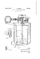
Fig. 1 is an axial sectional view of an embodiment of the invention; and Figs. 2 and 3 are sectional'details. Y Y
Referring more particularly to the drawings, there is shown a container 1, and an impelling means, advantageously a screw propeller S, carried by a shaft 3 and driven from any suitable source of power. The container may be of shape and dimensions required by particular circumstances, ordinarily a cylindrical shape being most desira-t ble.
The impeller is mounted in the lower portion of the container, and preferably the blades 2 are regulable as to pitch, this being provided by any suitable means, as for instance journalled stems 2a and set screws 9]) for tightening against the respective bladestems to hold them in desired pitch position.
In relation with the impelling means is a current guide in the form of a tubular shell,
1929. Serial No. 344,971.
the cross section of which may be of noncircular form, but which ordinarily is circular. Such current guide is regulable moreover as to its height in the container, whereby I it may be readily adapted to various amounts of liquid material under treatment. To such end, the guide is of a telescopic character, being made up of any preferred number of sections 4a, 46, it, these sections nesting closely so as to favor adju'stability without material space requirement. In thedetail shown. the section adjacent the impeller is held in fixed position, as by support rods or standards 5, and the sections 46, thence are telscopiv cally mounted thereon, the section 40a for instance being slightly flanged outwardly at its upper end, while the section 46 is correspondingly flanged inwardly at its lower end.
and so on. Means for raising and lowering v the sections are provided, for instance cables 6 attached to the upper section, and wound on drums 7 operated by shaft 8. The latter may be actuated by a hand wheel 9 through suitable gearing. lar guide may be extended to whatever length may be desired in view of the requirements at any given time, and the upper edge of the guide may be maintained at all times at a In this manner, the tubusuitable distance below the surface of the liquid so as 'to allow of circulation. If desired, a tell-tale or indicator 10 may be secured to the cable at a suitable distance above the top of the upper section of the tubular guide to facilitate maintaining proper submergence depth, it being then merely necessary to regulate the cable so thatthe indicator 10 is at the surface of the liquid.
It will be observed that the tubular guide divides the liquid mass undergoing treatment into two columns, an inner or central column and an outer or peripheral column, the tubular guide making a division therebetween; and accordingly the liquid mass may circulate efi'ectively, as set in motion by the agitating impeller. Moreover, the cross sectional areas within and without the tubular guide are preferably substantially equal, this being readily attained by dimensioning the tubular guide in accordance with the mathematical requirements of the areas of the concentric circle-s. In this manner, the area for circulatory action is equal inside and out with respect to the tubular guide, and an even circulation is favored. The same equality of 5 Circulatory area at all points may be furthered also by maintaining the distance between the lower edge of the tubular guide andthe floor of the container, and the distance: between the upper edge of the tubular guide and the surface of the liquid such as to be consistent with the cross sectional circulatory require ments referred to, and thus a circulatory circuit may be had which at all points ofl'ers' substantially equal freedom of flow.
The floor of the container is preferably recurved, as at 12,'the sweep of liquid thus being caused to exert ascouring action upon the bottom; and with absence of eddy currents in dead corner spaces, thedirect force of the current stream is made available, and consequently deposited materials are capable of being readily loosened up and put into circulation.
In order to check tendencies towards circular swirl of the entire fluid mass in the zone between thecontainer and the tubular guide, baffle plates 13- may be suitable positioned, a convenient mounting involving for instance channel forms 14 secured to the container walls, and witha baflie plate correspondingly flanged as at 15, such plate may be slid down the channel and into place, to project out into the space between container and tubular guide.
In large size units,.it isdesirable to make adequate provision'for mounting andlubrication of the impeller shaft, and as shown in Fig. 1, this may comprise a. stuffing box 16 and a step bearing 17 under the container floor. The bearing box furtliermoremay be provided with oil inlet and outlet pipes'18', 19, the former leading from a suitable source of oil supply and the latter. to a receiver. In this manner,.an adequate'supply of lubricant to the step bearing may be had under all conditions of usage. I
In operation, if it is desired to start with a small amount ofmaterial, the telescopic guide is collapsed into its lowest position,
the ring sections then nesting closely concentrically at the lower end of the container adjacent the impeller. WVith the starting material charged into'the container,.and the-impeller inmotion, the blades may beset at such pitch as to direct the current flow for example downwardly against the-floor. of the container, the liquidmass is thus churned and agitated, and with the upper edge ofthe guide maintained at a spaced distance below the surface of the liquid, a circulatorycircuit is had. \Vithan increased amount of liquid under treatment, the tubular guide is raised correspondingly, and by gauging its depth of submergence by'reference to the indicator 10, adjustment being had so as to maintain the indicator at the surface of the liquid, the height of the guide may at all times be set to correspond to the amount of liquid to be treated, whether of relatively small amount, or with a container full. As seen, also the churning and agitation proceeds, components which tend to settle out being set into vigorous motion, effecting progressive and thor' ough intermixture, and the mass circulates as a downwardly directed column inside of the tubular guide, thence impinging with a scouring action on the floor 12 and thence up in the-space between the container wall and the tubular guide, and over the top of the latter to the impeller. At the same time, the bafiling action-of the plates 13 checks circular swirling. One or more arms-11 may be arranged betweenthe tubular section to and the container, a convenient form being an extension of the arm of'the spider 4 to en'- gage for instance by a forked end over the platel3.
Instead. of setting the impeller blades to drive the material downwardly, the pitch may be reversed if desired so as to drive the centralicolumnupwardly, the material thence flowing downwardly between the tubular guide and the container wall and sweeping over'the bottom reenters past the impellers.
Mixtures which ordinarily are difiiculty kept. in suspension, asfor instance cement slurries, pulp mixtures, paint mixtures, etc, are thns readily handled,and by reason of the effective scouring action exerted at the hottomof the container, operations may be suspended if required, and on-restarting,. material caked at thebottom may be secured loose and put into uniform admixture. By reasonfurther of the regulable character of the tubular guide, as seen, compositions which include diflicultly miscible components and easily miscible components may be readily handled, the difiicultly miscible components being put in first, and these being brought to a desired. homogeneity, the tubular guide being set for such volume, and'with progressive addition of the other constituents, the tubular guide being regulated correspondingly,.the entire mass may. be brought to final homogeneity. Where desired also continuous-type operation may be as readily'had, the components being correspondingly supplied, and draw off at a bottom outlet being controlled propori ionately.
Other modes-of applying the principle of the invention may be employed, change being made as regards the details described, provided the steps or means stated inany of the following claims, or the equivalent of such, be employed.
I therefore particularly point out and distinctly claimas my invention i l. A method of agitating liquids, which comprises churning the liquid while moving it in central and peripheral columns in circuit, and irrespective of the amount of liquid maintaining the separation between central and peripheral portions at substantially con stant distances below the surface of the liquid and above the floor of the container for such liquid.
2. A method of agitating liquids, which comprises churning the material while moving it in a central column and a sharply separated peripheral zone with a recurved sweep between, the cross sectional area of the central column and the peripheral zone being substantially equal, and maintaining the separation between central and peripheral portions at substantially constant distances below the surface of the liquid and above the floor of the container for such liquid.
3. In apparatus of the character described, the combination of a container having a recurved floor, an impeller above such floor to propel fluid in the container, and means for equalizing circulation of the propelled fluid, said means including a tubular guide spaced within the container to provide a cross-sectional area within the guide substantially the same as that between the guide and the container.
4. In apparatus of the character described, the combination of an impeller of regulable pitch, a tubular guide, and a container having a floor adjacent the propeller presenting a recurved surface.
5. In apparatus of the character described, the combination of a container, an impeller, a tubular guide, vertical baflies, and means on the container walls to removably hold said baflies.
6. In apparatus of the character described, the combination of a container, an impeller, channel-form supports on the inner wall of said container. and b'aflle plates having flanges adapted to slide into such channels.
7 In apparatus of the character described, the combination of a container, an impeller at the lower portion thereof, said container having a recurved floor, a tubular guide of a proportion affording a cross sectional area therewithin substantially equal to the cross sectional area between the guide and the container, said guide being supported from the floor of the container at a distance affording substantially the same circulatory section as between the guide and the container wall, and means for maintaining the upper and lower edges of the guide respectively at uniform distances below the surface of the liquid undergoing treatment and above the bottom of such container.
8. In apparatus of the character described, the combination of a container an impeller at the lower portion thereof, a guide comprising a tubular section fixed adjacent the propeller and telescopic sections movable on said fixed section, means for regulating the depth of submergence of the top of such sections, and
means for checking rotational swirl between said guide and the container walls.
9. In apparatus of the character described, the combination of a container having a recurved floor, an impeller adjacent thereto, a
JACOB B. PERKINS.
Priority Applications (1)
| Application Number | Priority Date | Filing Date | Title |
|---|---|---|---|
| US344971A US1854761A (en) | 1929-03-07 | 1929-03-07 | Method of and apparatus for agitating |
Applications Claiming Priority (1)
| Application Number | Priority Date | Filing Date | Title |
|---|---|---|---|
| US344971A US1854761A (en) | 1929-03-07 | 1929-03-07 | Method of and apparatus for agitating |
Publications (1)
| Publication Number | Publication Date |
|---|---|
| US1854761A true US1854761A (en) | 1932-04-19 |
Family
ID=23352890
Family Applications (1)
| Application Number | Title | Priority Date | Filing Date |
|---|---|---|---|
| US344971A Expired - Lifetime US1854761A (en) | 1929-03-07 | 1929-03-07 | Method of and apparatus for agitating |
Country Status (1)
| Country | Link |
|---|---|
| US (1) | US1854761A (en) |
Cited By (9)
| Publication number | Priority date | Publication date | Assignee | Title |
|---|---|---|---|---|
| DE1254101B (en) * | 1965-09-01 | 1967-11-16 | Richard Vetter | Device for processing sourdough, yeast, old bread and the like. like |
| EP0454140A1 (en) * | 1990-04-26 | 1991-10-30 | Praxair Technology, Inc. | Broad liquid level gas-liquid mixing operations |
| US5454986A (en) * | 1994-08-04 | 1995-10-03 | Lessen; Martin | Down-flow batch mixing system |
| US6276826B1 (en) * | 1999-12-08 | 2001-08-21 | The Maitland Company | Apparatus for transporting and delivering substances |
| US6443613B1 (en) | 1999-12-08 | 2002-09-03 | The Maitland Company | Method for transporting and delivering substances |
| US20100008180A1 (en) * | 2006-07-03 | 2010-01-14 | Soren Friis Krogh | Apparatus for dissolving solid particles and liquid substances in a liquid |
| US20130157241A1 (en) * | 2011-12-16 | 2013-06-20 | Michael RULAND | Dynamic Illustration Generation System |
| US8944357B2 (en) | 2012-10-30 | 2015-02-03 | Whirlpool Corporation | Multifunctional food processing tool for use with a food processing device |
| US9016931B2 (en) | 2012-11-12 | 2015-04-28 | Sumter Transport | Tank agitation system with moveable shaft support |
-
1929
- 1929-03-07 US US344971A patent/US1854761A/en not_active Expired - Lifetime
Cited By (12)
| Publication number | Priority date | Publication date | Assignee | Title |
|---|---|---|---|---|
| DE1254101B (en) * | 1965-09-01 | 1967-11-16 | Richard Vetter | Device for processing sourdough, yeast, old bread and the like. like |
| EP0454140A1 (en) * | 1990-04-26 | 1991-10-30 | Praxair Technology, Inc. | Broad liquid level gas-liquid mixing operations |
| US5454986A (en) * | 1994-08-04 | 1995-10-03 | Lessen; Martin | Down-flow batch mixing system |
| US6276826B1 (en) * | 1999-12-08 | 2001-08-21 | The Maitland Company | Apparatus for transporting and delivering substances |
| US6443613B1 (en) | 1999-12-08 | 2002-09-03 | The Maitland Company | Method for transporting and delivering substances |
| US20100008180A1 (en) * | 2006-07-03 | 2010-01-14 | Soren Friis Krogh | Apparatus for dissolving solid particles and liquid substances in a liquid |
| US20130157241A1 (en) * | 2011-12-16 | 2013-06-20 | Michael RULAND | Dynamic Illustration Generation System |
| US9305466B2 (en) * | 2011-12-16 | 2016-04-05 | Michael RULAND | Dynamic illustration generation system |
| US8944357B2 (en) | 2012-10-30 | 2015-02-03 | Whirlpool Corporation | Multifunctional food processing tool for use with a food processing device |
| US9572458B2 (en) | 2012-10-30 | 2017-02-21 | Whirlpool Corporation | Multifunctional food processing tool for use with a food processing device |
| US9016931B2 (en) | 2012-11-12 | 2015-04-28 | Sumter Transport | Tank agitation system with moveable shaft support |
| US9573102B2 (en) | 2012-11-12 | 2017-02-21 | The Maitland Company | Tank agitation system with moveable shaft support |
Similar Documents
| Publication | Publication Date | Title |
|---|---|---|
| US2779574A (en) | Mixing or stirring devices | |
| US2157683A (en) | Device for mixing, sifting, and kneading | |
| US1854761A (en) | Method of and apparatus for agitating | |
| US2996287A (en) | Apparatus for incorporating fluids into liquids | |
| CN107322796A (en) | A kind of cement mortar agitating device for lifting mixing effect | |
| US2042308A (en) | Filter | |
| US2858020A (en) | Method and apparatus for separating slurry and like suspensions | |
| US3388893A (en) | Material handling device | |
| US2140315A (en) | Mixing apparatus | |
| US2078065A (en) | Portable mixer | |
| US2610836A (en) | Rotating plate mixing device | |
| US2444671A (en) | Liquid treatment tank with sludge removal means therefor | |
| GB1227844A (en) | ||
| US2337291A (en) | Apparatus for separating the constituents of petroleum emulsions | |
| US3669414A (en) | Mixing apparatus | |
| US3601369A (en) | Apparatus for mixing particulate materials | |
| GB1091554A (en) | Solvent extraction apparatus | |
| US2450107A (en) | Mixing vessel and deflector therefor | |
| US2076163A (en) | Mixer | |
| US2662642A (en) | Screw dewatering classifier | |
| GB2119668A (en) | Clarification apparatus | |
| US2520827A (en) | Mixing machine | |
| US1992451A (en) | Fluid mixing apparatus | |
| CN211411882U (en) | A device for producing lubricating oil for drilling fluid | |
| US2226023A (en) | Battery paste muller |