US1854738A - Dirt collector - Google Patents
Dirt collector Download PDFInfo
- Publication number
- US1854738A US1854738A US436745A US43674530A US1854738A US 1854738 A US1854738 A US 1854738A US 436745 A US436745 A US 436745A US 43674530 A US43674530 A US 43674530A US 1854738 A US1854738 A US 1854738A
- Authority
- US
- United States
- Prior art keywords
- dirt
- valve
- dirt collector
- chamber
- casing
- Prior art date
- Legal status (The legal status is an assumption and is not a legal conclusion. Google has not performed a legal analysis and makes no representation as to the accuracy of the status listed.)
- Expired - Lifetime
Links
- 239000012530 fluid Substances 0.000 description 6
- XLYOFNOQVPJJNP-UHFFFAOYSA-N water Substances O XLYOFNOQVPJJNP-UHFFFAOYSA-N 0.000 description 5
Images
Classifications
-
- B—PERFORMING OPERATIONS; TRANSPORTING
- B60—VEHICLES IN GENERAL
- B60T—VEHICLE BRAKE CONTROL SYSTEMS OR PARTS THEREOF; BRAKE CONTROL SYSTEMS OR PARTS THEREOF, IN GENERAL; ARRANGEMENT OF BRAKING ELEMENTS ON VEHICLES IN GENERAL; PORTABLE DEVICES FOR PREVENTING UNWANTED MOVEMENT OF VEHICLES; VEHICLE MODIFICATIONS TO FACILITATE COOLING OF BRAKES
- B60T17/00—Component parts, details, or accessories of power brake systems not covered by groups B60T8/00, B60T13/00 or B60T15/00, or presenting other characteristic features
- B60T17/002—Air treatment devices
-
- Y—GENERAL TAGGING OF NEW TECHNOLOGICAL DEVELOPMENTS; GENERAL TAGGING OF CROSS-SECTIONAL TECHNOLOGIES SPANNING OVER SEVERAL SECTIONS OF THE IPC; TECHNICAL SUBJECTS COVERED BY FORMER USPC CROSS-REFERENCE ART COLLECTIONS [XRACs] AND DIGESTS
- Y10—TECHNICAL SUBJECTS COVERED BY FORMER USPC
- Y10T—TECHNICAL SUBJECTS COVERED BY FORMER US CLASSIFICATION
- Y10T137/00—Fluid handling
- Y10T137/2931—Diverse fluid containing pressure systems
- Y10T137/3003—Fluid separating traps or vents
- Y10T137/3102—With liquid emptying means
-
- Y—GENERAL TAGGING OF NEW TECHNOLOGICAL DEVELOPMENTS; GENERAL TAGGING OF CROSS-SECTIONAL TECHNOLOGIES SPANNING OVER SEVERAL SECTIONS OF THE IPC; TECHNICAL SUBJECTS COVERED BY FORMER USPC CROSS-REFERENCE ART COLLECTIONS [XRACs] AND DIGESTS
- Y10—TECHNICAL SUBJECTS COVERED BY FORMER USPC
- Y10T—TECHNICAL SUBJECTS COVERED BY FORMER US CLASSIFICATION
- Y10T137/00—Fluid handling
- Y10T137/794—With means for separating solid material from the fluid
- Y10T137/8013—Sediment chamber
Definitions
- This invention relates to dirt collectors of the type employed to remove dirt from fluid under pressure as supplied to a fluid pressure system.
- Dirt collectors of the above type are provided with a dirt collecting chamber, in which water as well as dirt is collected from the air flowing through the device.
- the principal object of my invention is to provide means for draining oi? the water which may collect in the dirt collecting chamber of a dirt collector.
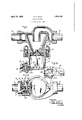
- FIG. 1 is a sectional view of a dirt collector showing my invention applied thereto;
- Fig. 2 an inverted plan view, partly in section, of the dirt collector shown in Fig. 1;
- Fig. 3 a fragmentary view, showing the operating handle of the drain cock.
- the dirt collector may comprise a casing 1, connected to sections 2 and 3 of a pipe through which fluid under pressure is supplied, said casing having a chamber 4 in which dirt is separated from the fluid flowing through the dirt collector.
- a casing 6 Secured to the casing 1 by bolts 5, is a casing 6, having a dirt collecting chamber 7.
- a valve 8 controls communication from chamber 1 to chamber 7 and said valve is supported by a stem 9, which is secured in a lug 10 of the casing 6.
- a boss 11 having a horizontally disposed conical bore in which is fitted a conical bushing 12.
- a conical plug valve 13 In the bushing 12 is disposed a conical plug valve 13, having a port 14. In one position of the valve 13, the port 14 connects a passage 15, leading from chamber 7 adjacent to the bottom wall with a passage 16 opening to the atmosphere.
- the valve 13 at one end is provided with a key section 17 to which is applied an operating handle 18.
- the handle 18 is curved to follow the contour of the casing 6, and is provided with a lug 19 adapted, when the handle is turned to open position, to engage a stop lug 20 cast integral with the boss 11.
- the opening in the boss 11 through which the bushing 12 and the valve 13 are introduced, is closed by a screw-threaded plug 21.
- valve 13 Normally, the valve 13 is maintained in the closed position, as shown in Fig. 1.
- the valve 13 When it is desired'to drain water from the dirt collecting chamber 7, the valve 13 is turned by the handle 18, so that the port 14 connects passage 15 with passage 16. The water in chamber 7 then drains out.
- the valve 18 When the valve 18 is in its full open position, the lug 19 on the handle 18 engages the lug 20.
- A. dirt collector for a fluid pressure system having a dirt collecting chamber, a check valve controlling communication from the fluid pressure system to said chamber, a. drain valve operative to drain water from said chamber, and a handle for operating said drain valve independently of said check valve.
Landscapes
- Engineering & Computer Science (AREA)
- Transportation (AREA)
- Mechanical Engineering (AREA)
- Check Valves (AREA)
Description
April 19, 1932. N. F.- HAYS 1,854,738
DIRT COLLECTOR File d March 18, 1930 'F igil INVENTOR.
NORA F. HAYS BYW M.
ATTORNEY Patented Apr. 19, 1932 UNITED STATES PATENT OFFICE NORA F. HAYS, 0F WILMERDING, PENNSYLVANIA, ASSIGNOR TO THE WESTINGHOUSE AIR BRAKE COMPANY, OF WILMERDING, PENNSYLVANIA, A CORPORATION OF PENNSYLVANIA DIRT COLLECTOR Application filed. March 18, 1930. serial No. 436,745.
This invention relates to dirt collectors of the type employed to remove dirt from fluid under pressure as supplied to a fluid pressure system.
Dirt collectors of the above type are provided with a dirt collecting chamber, in which water as well as dirt is collected from the air flowing through the device.
The principal object of my invention is to provide means for draining oi? the water which may collect in the dirt collecting chamber of a dirt collector.
In the accompanying drawings; Fig. 1 is a sectional view of a dirt collector showing my invention applied thereto; Fig. 2 an inverted plan view, partly in section, of the dirt collector shown in Fig. 1; and Fig. 3 a fragmentary view, showing the operating handle of the drain cock.
The dirt collector may comprise a casing 1, connected to sections 2 and 3 of a pipe through which fluid under pressure is supplied, said casing having a chamber 4 in which dirt is separated from the fluid flowing through the dirt collector. Secured to the casing 1 by bolts 5, is a casing 6, having a dirt collecting chamber 7. A valve 8 controls communication from chamber 1 to chamber 7 and said valve is supported by a stem 9, which is secured in a lug 10 of the casing 6.
Cast integral with the casing 6 is a boss 11, having a horizontally disposed conical bore in which is fitted a conical bushing 12. In the bushing 12 is disposed a conical plug valve 13, having a port 14. In one position of the valve 13, the port 14 connects a passage 15, leading from chamber 7 adjacent to the bottom wall with a passage 16 opening to the atmosphere.
The valve 13 at one end is provided with a key section 17 to which is applied an operating handle 18. The handle 18 is curved to follow the contour of the casing 6, and is provided with a lug 19 adapted, when the handle is turned to open position, to engage a stop lug 20 cast integral with the boss 11. The opening in the boss 11 through which the bushing 12 and the valve 13 are introduced, is closed by a screw-threaded plug 21.
Normally, the valve 13 is maintained in the closed position, as shown in Fig. 1. When it is desired'to drain water from the dirt collecting chamber 7, the valve 13 is turned by the handle 18, so that the port 14 connects passage 15 with passage 16. The water in chamber 7 then drains out. When the valve 18 is in its full open position, the lug 19 on the handle 18 engages the lug 20.
l/Vhile one illustrative embodiment of the invention has been described in detail, itis not my intention to limit its scope to that embodiment or otherwise than by the terms of the appended claim.
Having now described my invention, what I claim as new and desire to secure by Letters Patent, is:
A. dirt collector for a fluid pressure system having a dirt collecting chamber, a check valve controlling communication from the fluid pressure system to said chamber, a. drain valve operative to drain water from said chamber, and a handle for operating said drain valve independently of said check valve.
In testimony whereof I have hereunto set my hand, this 17th day of March, 1930.
NORA F. HAYS.
Priority Applications (1)
| Application Number | Priority Date | Filing Date | Title |
|---|---|---|---|
| US436745A US1854738A (en) | 1930-03-18 | 1930-03-18 | Dirt collector |
Applications Claiming Priority (1)
| Application Number | Priority Date | Filing Date | Title |
|---|---|---|---|
| US436745A US1854738A (en) | 1930-03-18 | 1930-03-18 | Dirt collector |
Publications (1)
| Publication Number | Publication Date |
|---|---|
| US1854738A true US1854738A (en) | 1932-04-19 |
Family
ID=23733655
Family Applications (1)
| Application Number | Title | Priority Date | Filing Date |
|---|---|---|---|
| US436745A Expired - Lifetime US1854738A (en) | 1930-03-18 | 1930-03-18 | Dirt collector |
Country Status (1)
| Country | Link |
|---|---|
| US (1) | US1854738A (en) |
Cited By (3)
| Publication number | Priority date | Publication date | Assignee | Title |
|---|---|---|---|---|
| US2692052A (en) * | 1950-06-01 | 1954-10-19 | Walter G Bihler | Liquid cleaner unit |
| US2792910A (en) * | 1953-10-14 | 1957-05-21 | Redniss Alexander | Cyclone separator |
| US3988133A (en) * | 1973-11-19 | 1976-10-26 | Alpha Sheet Metal Works, Inc. | Cyclone apparatus |
-
1930
- 1930-03-18 US US436745A patent/US1854738A/en not_active Expired - Lifetime
Cited By (3)
| Publication number | Priority date | Publication date | Assignee | Title |
|---|---|---|---|---|
| US2692052A (en) * | 1950-06-01 | 1954-10-19 | Walter G Bihler | Liquid cleaner unit |
| US2792910A (en) * | 1953-10-14 | 1957-05-21 | Redniss Alexander | Cyclone separator |
| US3988133A (en) * | 1973-11-19 | 1976-10-26 | Alpha Sheet Metal Works, Inc. | Cyclone apparatus |
Similar Documents
| Publication | Publication Date | Title |
|---|---|---|
| US1646640A (en) | Whistle control valve | |
| US2580575A (en) | Drain valve for sinks and the like | |
| US2169043A (en) | Bypass valve | |
| US1854738A (en) | Dirt collector | |
| US2128206A (en) | Automatic drainage apparatus | |
| US2153559A (en) | Valve | |
| US2096484A (en) | Bypass valve for dirt collectors | |
| US1648710A (en) | Combined trip and throttle valve | |
| US2069364A (en) | Valve | |
| US2385151A (en) | Automatic blow-off valve apparatus | |
| US2116626A (en) | Compression stop and drain valve | |
| US1850457A (en) | Valve | |
| US1936873A (en) | By-pass gate valve | |
| US1566238A (en) | Steam trap | |
| US2275132A (en) | Discharge valve | |
| US2204788A (en) | Air release valve for sewage lines | |
| US1406013A (en) | Governor valve for steam engines | |
| US1714300A (en) | Strainer and dirt collector | |
| US1838089A (en) | Steam trap | |
| US1639954A (en) | Two-way dbain valve | |
| US2646069A (en) | Flush tank valve | |
| US1879696A (en) | Pressure retaining valve | |
| US1712245A (en) | Locomotive throttle valve | |
| US1440827A (en) | Flushing apparatus | |
| US1426093A (en) | Muffler toilet valve |