US1854735A - Throttle control - Google Patents
Throttle control Download PDFInfo
- Publication number
- US1854735A US1854735A US35042529A US1854735A US 1854735 A US1854735 A US 1854735A US 35042529 A US35042529 A US 35042529A US 1854735 A US1854735 A US 1854735A
- Authority
- US
- United States
- Prior art keywords
- carburetor
- lever
- throttle control
- throttle
- speed
- Prior art date
- Legal status (The legal status is an assumption and is not a legal conclusion. Google has not performed a legal analysis and makes no representation as to the accuracy of the status listed.)
- Expired - Lifetime
Links
Images
Classifications
-
- F—MECHANICAL ENGINEERING; LIGHTING; HEATING; WEAPONS; BLASTING
- F01—MACHINES OR ENGINES IN GENERAL; ENGINE PLANTS IN GENERAL; STEAM ENGINES
- F01L—CYCLICALLY OPERATING VALVES FOR MACHINES OR ENGINES
- F01L1/00—Valve-gear or valve arrangements, e.g. lift-valve gear
-
- F—MECHANICAL ENGINEERING; LIGHTING; HEATING; WEAPONS; BLASTING
- F01—MACHINES OR ENGINES IN GENERAL; ENGINE PLANTS IN GENERAL; STEAM ENGINES
- F01L—CYCLICALLY OPERATING VALVES FOR MACHINES OR ENGINES
- F01L2710/00—Control of valve gear, speed or power
- F01L2710/006—Safety devices therefor
-
- Y—GENERAL TAGGING OF NEW TECHNOLOGICAL DEVELOPMENTS; GENERAL TAGGING OF CROSS-SECTIONAL TECHNOLOGIES SPANNING OVER SEVERAL SECTIONS OF THE IPC; TECHNICAL SUBJECTS COVERED BY FORMER USPC CROSS-REFERENCE ART COLLECTIONS [XRACs] AND DIGESTS
- Y10—TECHNICAL SUBJECTS COVERED BY FORMER USPC
- Y10T—TECHNICAL SUBJECTS COVERED BY FORMER US CLASSIFICATION
- Y10T137/00—Fluid handling
- Y10T137/7069—With lock or seal
- Y10T137/71—With seal
Definitions
- This invention relates to throttle control-.
- ling means for automobiles its object being to provide means whereby the usual throttling or controlling parts of the carburetor of an automobile may be sealed in such manner as to have their efiective motion limited, pre venting the operator from exceeding the prescribed speed limits in any manner except by breaking the seal.
- the invention has particular utility, for example, in those cases where distributors of automobiles purchased at a factory in one city have the automobiles delivered to them in another-city by operators who drive them overland, the present throttle control being applied to restrict operation of the throttle and prevent the driver from exceeding the relatively low speed limit, say twenty miles per hour, a new car should not be driven until its parts have been more or less worn in to relieve the stiffness and tightness of assembling.
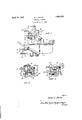
- Fig. 1 is a front view of the carburetor with my throttle control applied thereto and shown in dotted lines;
- Fig. 2 is a plan view of the control;
- Fig. 3 is a sectional elevation on the line 3-3 Fig. 2 looking in the direction of the arrows.
- the invention may be applied to any form of carburetor or other device for controlling the speed of an automobile. It is shown applied to a well-known type of carburetor including a casing, to which air is supplied through the hollow extension 2, the air flow being controlled by a suitable butterfly valve 3 actuated by a lever 4 connected to operating link 5, said lever 4 also actuating the sliding choke member 6.
- a suitable butterfly valve 3 actuated by a lever 4 connected to operating link 5, said lever 4 also actuating the sliding choke member 6.
- the butterfly valve 3 In the positions of the parts shown the butterfly valve 3 is wide open and the choke is closed, but by pulling on the link 5 the butterfly valve is more or less closed to cut ofi the air supply and the member 6 is moved upwardly to supply raw fuel to the carburetor for choke purposes.
- My throttle control device or attachment comprises :a :body vp onti'on 20 properly shaped Itolfitlthe rpa'rts Oifithe rparticulair carburetor "to which it .'.is .tolhe-ise'cnirefl.
- tthnee rearward marked .21 is in ft'lle r fonm 0d? :a :hollow sleeve designed Ito *ifit (over :the :post 19 before meferred to.
- the :body .is pro- vided with two rather reanward'ly :extending marked 23, seats against the upper *portion of zthe carburetor :connection 10 ata'bout the :flange zll thereof, while the ot-her extension :24 likewise :has a portion sseating against the carburetor con- .-nection110 andabove it :an sadditional extension in the form of a plate 25, the openasl'ot 25aiin'theendlof Whih forms two prongs enabllng said plate to be pushed in beneath the head of a cap screw 13.
- Extensions 23 and 24 are separated by a cavity or recess 29 through which the operating arm of lever 15 extends, while the extensions 24 and 21 are separated by a slot 30 in which rests the arm 16 of the throttle control lever. Indeed, the opposite sides of the extension 21 form fixed abutments to limit operating movement of the lever 15 to a fixed amount, usually a an eighth of an inch or so.
- the attachment or control device is applied to the carburetor of the car at the factory by loosening one of the cap screws 13 and pushing the attachment into place with the slotted end of its plate 25 beneath the head of the cap screw which is then screwed up tight to firmly secure the attachment.
- the sealing wire is then coiled around the manifold and'its ends are sealed with a seal, with the wire pulled up tight.
- the motion of the throttle lever is now limited by the new abutments or stops provided for its arms, the arrangement being such as to permit the throttle lever to freely move to proper idling position according to the setting of screw 18, but to limit its movement in the opposite direction to limit the car speed to a desired amount, say 20 miles per hour.
- the presenting of the attachment with the seal unbroken is. conclusive evidence that the car speed has not been exceeded.
- the attachment can then be removed and sent back tothe factory for attachment to another car for like delivery.
- a device removably secured to the carburetor and having a portion arranged to limit movement of said lever toward open position, and sealing means for preventing removal of said device from said carburetor without detection.
- a device having a portion arranged to extend into the normal path of said lever to toward open position, and means providing assembly of said carburetor and device and comprising a screw member and a sealing member arranged to prevent outward swinging of thedevice about said screw member.
Landscapes
- Engineering & Computer Science (AREA)
- Mechanical Engineering (AREA)
- General Engineering & Computer Science (AREA)
- Means For Warming Up And Starting Carburetors (AREA)
- Control Of Throttle Valves Provided In The Intake System Or In The Exhaust System (AREA)
Description
April 19, 1932. J DOLAN 1,854,735
THROTTLE CONTROL Filed March 27, 1929 INVENTOR ATTORN EYS Patented Apr. 19, 1932 UNITED STATES PATENT ()FFICE DAVID J. DOLAN, OF CHESTER, PENNSYLVANIA, ASSIG'NQR! 5.,0 THE .CARDEL COMPANY,
INC., OF CHESTER PENNSYLVANIA, A GQRBQBATION or DELAWARE THROTTLE CONTROL Application filed March 27, 1929. Serial No. 13503125.
This invention relates to throttle control-.
ling means for automobiles, its object being to provide means whereby the usual throttling or controlling parts of the carburetor of an automobile may be sealed in such manner as to have their efiective motion limited, pre venting the operator from exceeding the prescribed speed limits in any manner except by breaking the seal. The invention has particular utility, for example, in those cases where distributors of automobiles purchased at a factory in one city have the automobiles delivered to them in another-city by operators who drive them overland, the present throttle control being applied to restrict operation of the throttle and prevent the driver from exceeding the relatively low speed limit, say twenty miles per hour, a new car should not be driven until its parts have been more or less worn in to relieve the stiffness and tightness of assembling.
In the drawings, which represent one suitable embodiment of the invention, Fig. 1 is a front view of the carburetor with my throttle control applied thereto and shown in dotted lines; Fig. 2 is a plan view of the control; and Fig. 3 is a sectional elevation on the line 3-3 Fig. 2 looking in the direction of the arrows.
The invention may be applied to any form of carburetor or other device for controlling the speed of an automobile. It is shown applied to a well-known type of carburetor including a casing, to which air is supplied through the hollow extension 2, the air flow being controlled by a suitable butterfly valve 3 actuated by a lever 4 connected to operating link 5, said lever 4 also actuating the sliding choke member 6. In the positions of the parts shown the butterfly valve 3 is wide open and the choke is closed, but by pulling on the link 5 the butterfly valve is more or less closed to cut ofi the air supply and the member 6 is moved upwardly to supply raw fuel to the carburetor for choke purposes.
The mixture of gas and air produced by the carburetor passes out to the engine through the connection 10 provided with a flange 11 secured to the flange 12 of the intake manifold by cap screws 13. At 14 is above which speed through :the npena'ng .roif %the throttle :undisturbed :rp'ontions, one :of which,
shown the usual butterfly $9 to movementof lever 15 zbetrween'idling speed :and dull speed.
The foregoing parts :are all standard .eqnlpmentzand ttorni :no part :ef :the present inverrtion, WlhlGl-l is directed ate the meanszfior limiting for mestrlicting movement am? the (throttle contnol Llever .1'5:t0 less than its inormalimovenrent.
My throttle control device or attachment comprises :a :body vp onti'on 20 properly shaped Itolfitlthe rpa'rts Oifithe rparticulair carburetor "to which it .'.is .tolhe-ise'cnirefl. For this pin-- zp'ose,'in lthe farm shown, it is provided with tthnee rearward marked .21, is in ft'lle r fonm 0d? :a :hollow sleeve designed Ito *ifit (over :the :post 19 before meferred to. Said sleeve 21 may-be provided with a recess :22 in .zthat .side mext :to rthe .=st0p screw 5E8, so that ithe step screw 7 :22 into actual contact with the 1p ost 11.9., ieaviin'g the zidlingiposition "although "the :sleeve may the left imperforate and the stop screw may Jbe givensamewsettmgror adnustmentrsmas to engage the .iout-erzsunfaee of !the sleeve in idling position.
Above the extension '21 the :body .is pro- =vided with two rather reanward'ly :extending marked 23, seats against the upper *portion of zthe carburetor :connection 10 ata'bout the :flange zll thereof, while the ot-her extension :24 likewise :has a portion sseating against the carburetor con- .-nection110 andabove it :an sadditional extension in the form of a plate 25, the openasl'ot 25aiin'theendlof Whih forms two prongs enabllng said plate to be pushed in beneath the head of a cap screw 13. Said plate 25 may be attached to the extension 24: by screws 26, and the plate and extension are provided with a small opening 27 through which a wire may be passed and laid or coiled around the connection 10 or a portion of the intake manifold and secured together with a lead or other arm 16 alternately =enextensions, one 10f which,
{can project 2 valve actuated by lever' item control the speed iofzeng ime suitable seal 28 such as is used on railway car doors and in like places.
The attachment or control device is applied to the carburetor of the car at the factory by loosening one of the cap screws 13 and pushing the attachment into place with the slotted end of its plate 25 beneath the head of the cap screw which is then screwed up tight to firmly secure the attachment. The sealing wire is then coiled around the manifold and'its ends are sealed with a seal, with the wire pulled up tight. As a result,'the motion of the throttle lever is now limited by the new abutments or stops provided for its arms, the arrangement being such as to permit the throttle lever to freely move to proper idling position according to the setting of screw 18, but to limit its movement in the opposite direction to limit the car speed to a desired amount, say 20 miles per hour. After the car has been driven to its destination at the distributors station, the presenting of the attachment with the seal unbroken is. conclusive evidence that the car speed has not been exceeded. The attachment can then be removed and sent back tothe factory for attachment to another car for like delivery.
What I claim is:
1. In combination with a carburetor having a throttle control lever, a device removably secured to the carburetor and having a portion arranged to limit movement of said lever toward open position, and sealing means for preventing removal of said device from said carburetor without detection.
2. In combination with a carburetor having a throttle lever, a device having a portion arranged to extend into the normal path of said lever to toward open position, and means providing assembly of said carburetor and device and comprising a screw member and a sealing member arranged to prevent outward swinging of thedevice about said screw member.
In testimony whereof I hereby affix my signature.
DAVID J. DOLAN.
very small amount, such as limit the swing ofsaid lever
Priority Applications (1)
| Application Number | Priority Date | Filing Date | Title |
|---|---|---|---|
| US35042529 US1854735A (en) | 1929-03-27 | 1929-03-27 | Throttle control |
Applications Claiming Priority (1)
| Application Number | Priority Date | Filing Date | Title |
|---|---|---|---|
| US35042529 US1854735A (en) | 1929-03-27 | 1929-03-27 | Throttle control |
Publications (1)
| Publication Number | Publication Date |
|---|---|
| US1854735A true US1854735A (en) | 1932-04-19 |
Family
ID=23376660
Family Applications (1)
| Application Number | Title | Priority Date | Filing Date |
|---|---|---|---|
| US35042529 Expired - Lifetime US1854735A (en) | 1929-03-27 | 1929-03-27 | Throttle control |
Country Status (1)
| Country | Link |
|---|---|
| US (1) | US1854735A (en) |
-
1929
- 1929-03-27 US US35042529 patent/US1854735A/en not_active Expired - Lifetime
Similar Documents
| Publication | Publication Date | Title |
|---|---|---|
| US1167145A (en) | Butterfly-valve system for carbureters. | |
| US1854735A (en) | Throttle control | |
| US2035191A (en) | Controlling fuel of internal combustion engines | |
| US4962737A (en) | Device for controlling at least one throttle cross-section at a control opening | |
| US2010206A (en) | Carburetor | |
| US1917790A (en) | Fan control governor | |
| US2766004A (en) | Carburetor valve with adjustable stop | |
| US1214322A (en) | Engine attachment. | |
| US1764621A (en) | Choke-operated throttle | |
| US2153047A (en) | Governor | |
| US1341762A (en) | Carbureter control | |
| US1347199A (en) | Choke-valve | |
| US2249439A (en) | Governor | |
| US1920067A (en) | The cardel company, inc. | |
| US1414935A (en) | cox and r | |
| US1879719A (en) | Motor vehicle device | |
| US1162047A (en) | Governor for explosion-engines. | |
| US2059410A (en) | Vacuum control device for engines | |
| US1253266A (en) | Air-inlet device. | |
| US1307374A (en) | Carbureter | |
| US1198123A (en) | Carbureter-adjusting means. | |
| US1096962A (en) | Governor. | |
| US2202423A (en) | Combined throttle and governor device | |
| US1986574A (en) | Carburetor | |
| US1181128A (en) | Automatic priming device for carbureters. |