US1854638A - Surface waxing machine - Google Patents
Surface waxing machine Download PDFInfo
- Publication number
- US1854638A US1854638A US228825A US22882527A US1854638A US 1854638 A US1854638 A US 1854638A US 228825 A US228825 A US 228825A US 22882527 A US22882527 A US 22882527A US 1854638 A US1854638 A US 1854638A
- Authority
- US
- United States
- Prior art keywords
- shaft
- wax
- bore
- plunger
- shell
- Prior art date
- Legal status (The legal status is an assumption and is not a legal conclusion. Google has not performed a legal analysis and makes no representation as to the accuracy of the status listed.)
- Expired - Lifetime
Links
- 238000004018 waxing Methods 0.000 title description 18
- 239000001993 wax Substances 0.000 description 54
- 239000000463 material Substances 0.000 description 16
- 238000005498 polishing Methods 0.000 description 13
- 239000000243 solution Substances 0.000 description 11
- 239000012530 fluid Substances 0.000 description 9
- 230000033001 locomotion Effects 0.000 description 9
- 230000005540 biological transmission Effects 0.000 description 4
- 238000010438 heat treatment Methods 0.000 description 4
- 229910000831 Steel Inorganic materials 0.000 description 2
- 238000013019 agitation Methods 0.000 description 2
- 230000001680 brushing effect Effects 0.000 description 2
- 230000000994 depressogenic effect Effects 0.000 description 2
- 230000000694 effects Effects 0.000 description 2
- 239000007788 liquid Substances 0.000 description 2
- 238000000034 method Methods 0.000 description 2
- 239000010959 steel Substances 0.000 description 2
- 230000001112 coagulating effect Effects 0.000 description 1
- 230000015271 coagulation Effects 0.000 description 1
- 238000005345 coagulation Methods 0.000 description 1
- 238000010276 construction Methods 0.000 description 1
- 239000007799 cork Substances 0.000 description 1
- 230000001419 dependent effect Effects 0.000 description 1
- 230000005484 gravity Effects 0.000 description 1
- 230000003534 oscillatory effect Effects 0.000 description 1
- 238000010422 painting Methods 0.000 description 1
- 230000002093 peripheral effect Effects 0.000 description 1
- 239000011148 porous material Substances 0.000 description 1
- 238000010186 staining Methods 0.000 description 1
- 238000003756 stirring Methods 0.000 description 1
- 239000000126 substance Substances 0.000 description 1
- 239000000725 suspension Substances 0.000 description 1
- 239000002023 wood Substances 0.000 description 1
Images
Classifications
-
- A—HUMAN NECESSITIES
- A47—FURNITURE; DOMESTIC ARTICLES OR APPLIANCES; COFFEE MILLS; SPICE MILLS; SUCTION CLEANERS IN GENERAL
- A47L—DOMESTIC WASHING OR CLEANING; SUCTION CLEANERS IN GENERAL
- A47L11/00—Machines for cleaning floors, carpets, furniture, walls, or wall coverings
- A47L11/40—Parts or details of machines not provided for in groups A47L11/02 - A47L11/38, or not restricted to one of these groups, e.g. handles, arrangements of switches, skirts, buffers, levers
- A47L11/4036—Parts or details of the surface treating tools
- A47L11/4038—Disk shaped surface treating tools
-
- A—HUMAN NECESSITIES
- A47—FURNITURE; DOMESTIC ARTICLES OR APPLIANCES; COFFEE MILLS; SPICE MILLS; SUCTION CLEANERS IN GENERAL
- A47L—DOMESTIC WASHING OR CLEANING; SUCTION CLEANERS IN GENERAL
- A47L11/00—Machines for cleaning floors, carpets, furniture, walls, or wall coverings
- A47L11/02—Floor surfacing or polishing machines
- A47L11/10—Floor surfacing or polishing machines motor-driven
- A47L11/14—Floor surfacing or polishing machines motor-driven with rotating tools
- A47L11/16—Floor surfacing or polishing machines motor-driven with rotating tools the tools being disc brushes
- A47L11/161—Floor surfacing or polishing machines motor-driven with rotating tools the tools being disc brushes with supply of cleaning agents
-
- A—HUMAN NECESSITIES
- A47—FURNITURE; DOMESTIC ARTICLES OR APPLIANCES; COFFEE MILLS; SPICE MILLS; SUCTION CLEANERS IN GENERAL
- A47L—DOMESTIC WASHING OR CLEANING; SUCTION CLEANERS IN GENERAL
- A47L11/00—Machines for cleaning floors, carpets, furniture, walls, or wall coverings
- A47L11/40—Parts or details of machines not provided for in groups A47L11/02 - A47L11/38, or not restricted to one of these groups, e.g. handles, arrangements of switches, skirts, buffers, levers
- A47L11/4063—Driving means; Transmission means therefor
- A47L11/4069—Driving or transmission means for the cleaning tools
-
- A—HUMAN NECESSITIES
- A47—FURNITURE; DOMESTIC ARTICLES OR APPLIANCES; COFFEE MILLS; SPICE MILLS; SUCTION CLEANERS IN GENERAL
- A47L—DOMESTIC WASHING OR CLEANING; SUCTION CLEANERS IN GENERAL
- A47L11/00—Machines for cleaning floors, carpets, furniture, walls, or wall coverings
- A47L11/40—Parts or details of machines not provided for in groups A47L11/02 - A47L11/38, or not restricted to one of these groups, e.g. handles, arrangements of switches, skirts, buffers, levers
- A47L11/408—Means for supplying cleaning or surface treating agents
- A47L11/4083—Liquid supply reservoirs; Preparation of the agents, e.g. mixing devices
-
- A—HUMAN NECESSITIES
- A47—FURNITURE; DOMESTIC ARTICLES OR APPLIANCES; COFFEE MILLS; SPICE MILLS; SUCTION CLEANERS IN GENERAL
- A47L—DOMESTIC WASHING OR CLEANING; SUCTION CLEANERS IN GENERAL
- A47L11/00—Machines for cleaning floors, carpets, furniture, walls, or wall coverings
- A47L11/40—Parts or details of machines not provided for in groups A47L11/02 - A47L11/38, or not restricted to one of these groups, e.g. handles, arrangements of switches, skirts, buffers, levers
- A47L11/408—Means for supplying cleaning or surface treating agents
- A47L11/4088—Supply pumps; Spraying devices; Supply conduits
Definitions
- the object of the invention is to provide improvements in surface waxing machines, and especially those designed for the waxing and polishing of floors and similar surfaces in residences and public halls.
- the device has been particularly constructed for the application of various forms of wax, it is to be understood that reference to wax or waxing of surfaces is intended to include and imply broadly a device for not only waxing, but also for polishing, butting, painting, staining, etc. an surface and with any material for which t e device is adapted.
- Another object is to provide a device of J this character, employing a plurality of elements, such as brushes or the like, rotatable in opposite directions in a common plane, so that when in operation and the device is tilted into a position such that the elements are not in uniform cooperation with the surface being treated, but cooperate with the surface substantially along a tangent to the peripheries of the said elements, the device is under no tendency to move in either direction along such tangent, but remains in a fixed position until and as moved in any desired direction from such position.
- elements such as brushes or the like
- a further object is to provide broadly in such a machine means for heating and maintaining the wax, or other material, at a substantially given redetermined temperature, to insure its fiowlng freely through the channels of the device before it reaches the surface being finished, to insure its entering the pores of said surface 11 on striking the same, as well as insuring a better resulting finish after manipulation by the brushes of the device upon such surface.
- Still another and very important object is to provide in a machine of this character means for ejecting the usual waxes employed for polishing wood and similar surfaces in such manner and unfailing regularity that the brushes or other applicators are able to distribute said waxes continuously and evenly as long as the device is in operation.
- Such ejecting means broadly comprises an oscillatory mechanism which runs at high speed of vibration and substantially noiseless operation, and insures a regularity of flow of wax at rather widely varying temperatures.
- a still further object is to provide in a device of this character the combination of a casing, a motor within said casing and provided with a normally horizontal shaft, a pair of shafts adapted to rotatably support brushing, polishing, or bufling, elements and extending preferably in parallel relation with each other and at right-angles to said driving shaft, said last-named shafts being driven by said driving shaft through suitable medium such as worm-gearing, with a reservoir, one or more channels to lead liquid wax from said reservoir towards said elements, reciprocatory means having a joggling motion operative to positively propel the wax through said one or more channels and through suitable corresponding nozzles, and means to prevent the flow of wax, or other material, when the device is not in use.
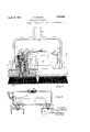
- Fig. 1 is a front elevational view of one embodiment of the invention and showing a portion thereof in vertical section
- Fig. 2 is a top plan view of the invention
- Fig. 3 is a section on the line 3-3 of Fig. 1; Fig.
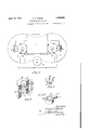
- Fig. 4 is an end elevation with a part of the device in section;
- Fig. 5 is a vertical longitudinal sectional view of the reservoir and showing in elevation a heating unit operatively positioned therein;
- Fig. 6 is a perspective view of a fragmentary portion of a unit which comv prises anti-frictional bearings for the applivided with 'a peripheral depending flange 4 and integral upwardly extending enlarged bosses 5, to which are pivotally secured at 6 the oppositely positioned parallel arms 7 of a yoke 8, having a socket 9, adapted to receive a handle (not shown).
- Each of the bosses 5 is'provided with a bore 10 in which is ositioned the unit shown in Fig. 6 and which ore upwardly is enlarged to provide a chamberll normally closed b 'a cap 12, having a threaded bore 13 throng which adjustably extends a similarly threaded pin 14, having a knurledfinger-engaging knob 15 upon its outer end, and upon its inner end has secured thereto in any suitable manner a preferably case-hardened enlargement 16.
- the unit shown in, detail in Fig. 6 comprises an outer, preferably steel cylinder 17, the o posite ends of which are provided with annuliir grooves 18, in which are normally secured by a press fit retainer or closure discs 19, having central apertures 20.
- an anti-friction unit 21 between which units in the central portion of said cylinder there is a ring 22, provided with an internal annular groove 23, while at one point a radial bore 24 leads from said last-named groove outwardly and communicates with an aperture 25 in the side of the cylinder 17. Said rin is then separated from each of said units 21 y means of cork or similar washers 25 and steel or similar gaskets 25', which latter bear against the respective anti-friction units.
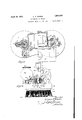
- the said bearing units are normally positioned by means of a drive fit within the bores 10 of the bosses 5. Through each of them extends a shaft 26, having an axial bore 27, and radial bores 28 which connect the interior of the ring groove 23 with said axial bore. .Within sa1d last-mentioned bore there is positioned a reciprocatory pin 29, of less diameter than said bore, except that its lower extremit is provided with a conical head 29 which, w ile not of the same diameter as said The otherwise continuous interior of the bore 27 is broken b a radially inwardly extending annular ange 30, against which presses one end of a coil spring 31, the other end of which latter engages the adjacent end of a sleeve 32 secured to said pin.
- a collar 33 (shown in detail in Fig. 8), having an integral shoulder 34, provided in one direction with a slanting surface 35, and in the opposite direction with an abrupt surface 36, which lies in a plane preferably coincident with the axis of said pin, and said collar and shoulder being so positioned that the latter engages the slanting surface 37 of a cam 38," which is secured to the under or inner surface of the boss closure 12 in any suitable manner, as for instance by the stud 39 carried by the cam being secured within an aperture 40 in said closure.
- the lower end portion of the shaft 26 is provided with a flange 41, which is separated from the lower end portion of said cylinder unit by a gasket 42.
- said shaft is threaded to receive an internally threaded axially bored member 43, the lower portion of which latter is hollow and is surrounded by a cylindrical flange 44, around which and secured to said bored member in any suitable manner is the centrally bored block 45 of a brush 46, or other desired form of brushing, buffing or polishing member.
- the lower end of said shaft is reduced at 47 within the hollow portion of said brush-block and is threaded to receive a threaded cap 48, which is provided with a central'aperture 49, opening outwardly into a preferably concave surface 50, said cap comprising a nozzle through which the particular material such as wax is ejected into the surrounding brush.
- the motor armature 1 is provided with a shaft 51, having worm teeth 52 in engagement with a worm gear 53, which is keyed to the shaft 26 beneath a nut 54, while separating said gear from the upper end of the said cylinder unit is a washer 55.
- rotation of the armature rotates each of the shafts 26, and in so doing also rot-ates the pin 29 and shouldered collar 33, which causes said shoulder upon contacting with the cam 38 to be depressed against the tension of the spring 31.
- the pins head 29 is thus caused to move suddenly downwardly with the result that wax or other material within the bore of said shaft is forced through the aperture 49 and into the brushes, after which the tension of said spring causes said pin and its head to move upwardly to its original position, where it remains until again depressed by said cam.
- the motor-supporting base 3 is other suitably shape provided with a pair of spaced integral standards 56, having concave up er surfaces 57 upon which is sup orteda cy indrical or tank or reservoir. 58, having a filling port, normally closed by a plug or cup 59-.
- the lower portion of the curved wall of said tank is apertured-at 60 to receive the end portion of a bolt 61, which extends through a bore 62 in each of the standards 56.
- any well known type of electric heater unit 63 from which wires 64 lead to a suitable source of electric current.
- the lower portion of said tank is provided with additional outlet apertures 65, which communicate through interposed washers 66 with the ends of diagonally extending bores 67- in each of the standards 56, said communicating with the apertures in the respective cylinder units.
- wax which it has been found will render a most desirable wax finish, it is essential to maintain the wax in uniform suspension and advisable to heat the same, in order to insure its steady flow through a small orifice 'with-.
- the present improved method therefore consists in first heating the wax when necessary or advisable within the reservoir, whence the solution flows through the diagonally extendingpassageway 67 into the chamber 23 surrounding the shaft 26, whence it proceeds into and downwardly through the bores 28 and 27 in said shaft towards the cap 50, and as the cam 38 depresses the pin 29, the waxy solution within said last-named bore asses around and beneath the head of the plston 29, which in descending forces the solution through the orifice 29 and thence through the flange 44 in theplate 43 to which the brush-back 45 is attached, whence the drops of'said solution fall upon the floor or other surface beneath each of the respective applicator or brush elements 46, which of course are rotating at relatively high speed.
- a leak-proof chamber is provided around the brush spindle or shaft, which also constitutes a mixing or agitation chamber in which the wax is prevented from congealing, and in which said shaft breaks up possible coagulation after the machine has been standing idle, the four intake holes in the shaft agitating the solution and at the same time admitting the wax to the axial bore leading to the nozzle.
- This agitation commenced by the revolving intake” holes, is kept up by the reciprocation of the plunger throughout the flow of the wax. toward the nozzle and is discharged therefrom.
- this agitating mechanism breaks up any coagulaferred to is not a gentle stirring but is in the nature of churning.
- a shaft hav ng intersecting. laterally inwardly and axially extending bores, with a unit support. comprising a shell, formed by a cylindrical member and apertured end members unitarily secured in said first memher and through which said shaft extends, a plurality of anti-friction bearings within said shell adjacent to said end members, and a ring surrounding said shaft within said shell and having an internal groove opening radially inwardly againstsaid shaft and adapted to receive fluid material for continuous transmission into said intersecting bores.
- ha waxing machine the combination of a shaft having intersect ng. laterally inwardly and axially extending bores, with a unit support, comprising a shell, formed by a cylindrical member and apertured end members unitarily secured in said first member and through which said shaft extends, a plurality of anti-friction bearngs within said shell adjacent to said end members, a ring surrounding said shaft within said shell and having an internal oove opening radiallyinwardly a ainst said shaft. and adapted to receive fiui mission into. said intersecting bores, and fluid-tight compressible gaskets surrounding said shaft adjacent to said ring, to yieldingly position said ring and to prevent the escape of such material from said shell other than throulgh said bores.
- a waxing machine the combination of a shaft having a bore, a restricted discharge aperture at one end of said bore, a plunger within said bore, and means to antomatically reci rocate said longer in synchronism with t e rotation 0 said shaft.
- a shaft having a bore, a restricted discharge aperture at oneend of said bore a plunger of less diameter than and movable within said bore, a head upon and lar er than said plunger but sufiiciently smallert an said bore to permit the passage of a sluggish fluid, and means to automatically reciprocate said plunger in synchronism with the rotation of said shaft.
- a shaft having a bore, a restricted discharge aperture at one end of said bore, a plunger of less diameter than and movable within said bore, ahead upon and larger than said plunger but sufficiently smaller than said bore to permit the passage of a sluggish fluid, a shoulder carried by said plunger, and a cam carried by a fixed portion of the machine, whereby rotation of said shaft and plunger causes the latter to reciprocate in synchronism with said otation.
- a shaft having a bore, a restricted discharge aperture at one end of said bore, a plunger within said bore means to automatically reciprocate said plunger in synchronism with the rotation of said shaft, and means to close said discharge aperture when the device is not in operatio v 10.
- a shaft having a bore, a restricted discharge aperture at one end of said bore, a plunger of less diameter than and movable within said bore, a head upon and larger than said plunger but sufliciently smaller'than said bore to permit the passage of a sluggish fluid means to automatically reciprocate said plunger in synchronism with the rotation of said shaft, and means engageable with said material for continuous trans-,-
- a shaft having a bore, a restricted discharge aperture at one end of said bore, a plunger of less diameter than and movable within said bore, a head upon and larger than said, plunger but sufliciently smaller than said bore to permit the passage of a fluid, a shoulder carried by said plunger, a cam carried by a fixed portion of the machine, whereby rotation of said shaft and plunger causes the latter to reciprocate in synchronism with said rotation, and manually adjustable means cooperating with said plunger to prevent its movement and to effect a closure of said discharge aperture when the device is not in operation.
- a wax-applying machine comprising a rotatable shaft having a channel therein to conduct wax, an ejecting valve within said channel, resilient means to yieldingly maintain said valve in one position, a surfaceengaging element carried by said shaft and having an aperture, and means carried by sluggish said shaft for moving said valve against said resilient means in timed relation with the rotation of said shaft to periodically eject the fluid through the aperture of said element in small quantity.
- a bored drive shaft for a polishing brush said bore extending axially thru one end of the shaft, a rod, an enlargement on the rod within the bore for agitating wax as it passes thru the bore, means for partially closing the bore of the shaft, and means for revolving the shaft and the rod.
- the device of claim 13 plus means for causing the rod to completely close the bore to prevent discharge of wax when the device is not in use.
- a polishing element In a waxer, a polishing element, a reservoir for wax. a passage having a restricted orifice at its end terminating short of the surface to be polished for conveying wax to such surface, and a reciprocating pump head at the end of said passage for forcibly ejecting wax directly to said surface thru said restricted orifice.
- a polishing element In a waxer, a polishing element, means for driving said element, a wax reservoir, means for conducting wax from the reservoir to the surface to be waxed, and means operative at a speed dependent upon the speed of the driving means for agitating the wax as it passes through the conducting means and for controlling the flow of the wax thru said conducting means.
- a motor driven polishing member In a waxing machine, a motor driven polishing member, a wax reservoir, means for conducting wax from the reservoir to the surface to be waxed, and means for agitating the wax immediately prior to discharge to the surface to be treated.
- the agitating means has rapid vibratory motion and controls in positive fashion the flow of wax.
- the polishing member is rotary, the agitating means includes a headed rod vibrated by the motor, said head at one point of its cycle permitting free flow of the wax, at another point accelerating the flow, and at still another point stopping the flow.
- polishing member is an annular rotatable brush
- agitating means is actuated only during rotation of the brush and serves also to positively eject wax thru the central space of the brush.
- a motor In a waxer, a motor, a vertical hollow shaft driven by said motor, means for conducting wax thru the hollow of the shaft to the surface to be waxed and polished, means within the hollow of the shaft for agitating the wax as it flows thru the shaft, and a rotary polishing member on said shaft.
- a rotary brush having a hollow shaft, a reservoir, means for conducting wax from the reservoir thru the shaft and to the surface to be waxed, and means within the shaft and rotatable therewith for alternately ejecting wax and interrupting the flow of the wax.
- a wax conveying tube having a restricted opening at one end, a valve movable in said tube to close said opening, a polishing member, and a motor for actuating said member and for moving said valve, said valve being smaller in diameter than the tube so as to fit loosely therein, whereby the movement of the valve in the tube will agitate the wax.
Landscapes
- Finish Polishing, Edge Sharpening, And Grinding By Specific Grinding Devices (AREA)
Description
April 19, 1932. c, woogs 1,854,638
SIjRFACE WAXING MACHINE Original Filed Oct. 26. 1927 3 Sheets-Sheet 2 Jnremoii C/imonE Wboas,
A ril 19, 1932. c. E. WOODS SURFACE WAXING MACHINE I Original Filed Oct. 26. 1927 3 Sheets-Sheet 5 jive/#02: 07mm E 770005,
C79 flfforngy.
Patented Apr. 19, 1932 UNITED STATES PATENT OFFICE;
CLINTON E. WOODS, OF PHILADELPHIA, PENNSYLVANIA;.JULIA IL WOODS, ADMINIQ. TRATRIX OF SAID CLINTON E. WOODS, DECEASEIL-ASSIGNOR TO JULIA E. WOODS INDIVIDUALLY, OF YEADON, PENNSYLVANIA SURFACE WAXING MACHINE Application filed October 26, 1927, Serial No. 228,825. Renewed August '28, 1929.
The object of the invention is to provide improvements in surface waxing machines, and especially those designed for the waxing and polishing of floors and similar surfaces in residences and public halls. However, while the device has been particularly constructed for the application of various forms of wax, it is to be understood that reference to wax or waxing of surfaces is intended to include and imply broadly a device for not only waxing, but also for polishing, butting, painting, staining, etc. an surface and with any material for which t e device is adapted.
Another object is to provide a device of J this character, employing a plurality of elements, such as brushes or the like, rotatable in opposite directions in a common plane, so that when in operation and the device is tilted into a position such that the elements are not in uniform cooperation with the surface being treated, but cooperate with the surface substantially along a tangent to the peripheries of the said elements, the device is under no tendency to move in either direction along such tangent, but remains in a fixed position until and as moved in any desired direction from such position.
A further object is to provide broadly in such a machine means for heating and maintaining the wax, or other material, at a substantially given redetermined temperature, to insure its fiowlng freely through the channels of the device before it reaches the surface being finished, to insure its entering the pores of said surface 11 on striking the same, as well as insuring a better resulting finish after manipulation by the brushes of the device upon such surface.
Still another and very important object is to provide in a machine of this character means for ejecting the usual waxes employed for polishing wood and similar surfaces in such manner and unfailing regularity that the brushes or other applicators are able to distribute said waxes continuously and evenly as long as the device is in operation. Such ejecting means broadly comprises an oscillatory mechanism which runs at high speed of vibration and substantially noiseless operation, and insures a regularity of flow of wax at rather widely varying temperatures.
It has been found that the waxes in general use for finishin floors and similar surfaces will not satisfactorily flow through a small nozzle even at a high temperature and under high pressure, and that if the nozzle were made large enough topass the wax freely, a size would be reached such that an overabundance of wax would be ejected towards and upon the given surface. However, this peculiar characteristic of surfacefinishing waxes has been overcome by rapidly vibrating a part of the mechanism, such for instance as a piston-like plunger, and arresting its motion suddenly, to the end that the resulting joggle prevents the wax from congrcgating and coagulating within its channel, and causes it to be ejected regularly and in relatively small globules towards and upon the particular surface.
And a still further object is to provide in a device of this character the combination of a casing, a motor within said casing and provided with a normally horizontal shaft, a pair of shafts adapted to rotatably support brushing, polishing, or bufling, elements and extending preferably in parallel relation with each other and at right-angles to said driving shaft, said last-named shafts being driven by said driving shaft through suitable medium such as worm-gearing, with a reservoir, one or more channels to lead liquid wax from said reservoir towards said elements, reciprocatory means having a joggling motion operative to positively propel the wax through said one or more channels and through suitable corresponding nozzles, and means to prevent the flow of wax, or other material, when the device is not in use.
In addition to the foregoing, the invention comprises further details of construction and operation which are fully brought out in the following description, when read in conjunction with the accompanying drawings, in which Fig. 1 is a front elevational view of one embodiment of the invention and showing a portion thereof in vertical section; Fig. 2 is a top plan view of the invention; Fig. 3 is a section on the line 3-3 of Fig. 1; Fig.
4 is an end elevation with a part of the device in section; Fig. 5 is a vertical longitudinal sectional view of the reservoir and showing in elevation a heating unit operatively positioned therein; Fig. 6 is a perspective view of a fragmentary portion of a unit which comv prises anti-frictional bearings for the applivided with 'a peripheral depending flange 4 and integral upwardly extending enlarged bosses 5, to which are pivotally secured at 6 the oppositely positioned parallel arms 7 of a yoke 8, having a socket 9, adapted to receive a handle (not shown).
Each of the bosses 5 is'provided with a bore 10 in which is ositioned the unit shown in Fig. 6 and which ore upwardly is enlarged to provide a chamberll normally closed b 'a cap 12, having a threaded bore 13 throng which adjustably extends a similarly threaded pin 14, having a knurledfinger-engaging knob 15 upon its outer end, and upon its inner end has secured thereto in any suitable manner a preferably case-hardened enlargement 16. The unit shown in, detail in Fig. 6 comprises an outer, preferably steel cylinder 17, the o posite ends of which are provided with annuliir grooves 18, in which are normally secured by a press fit retainer or closure discs 19, having central apertures 20. Within said cylinder adjacent to each of said disc closures is an anti-friction unit 21, between which units in the central portion of said cylinder there is a ring 22, provided with an internal annular groove 23, while at one point a radial bore 24 leads from said last-named groove outwardly and communicates with an aperture 25 in the side of the cylinder 17. Said rin is then separated from each of said units 21 y means of cork or similar washers 25 and steel or similar gaskets 25', which latter bear against the respective anti-friction units.
The said bearing units are normally positioned by means of a drive fit within the bores 10 of the bosses 5. Through each of them extends a shaft 26, having an axial bore 27, and radial bores 28 which connect the interior of the ring groove 23 with said axial bore. .Within sa1d last-mentioned bore there is positioned a reciprocatory pin 29, of less diameter than said bore, except that its lower extremit is provided with a conical head 29 which, w ile not of the same diameter as said The otherwise continuous interior of the bore 27 is broken b a radially inwardly extending annular ange 30, against which presses one end of a coil spring 31, the other end of which latter engages the adjacent end of a sleeve 32 secured to said pin. Finally, to said sleeve there is secured in any suitable manner a collar 33 (shown in detail in Fig. 8), having an integral shoulder 34, provided in one direction with a slanting surface 35, and in the opposite direction with an abrupt surface 36, which lies in a plane preferably coincident with the axis of said pin, and said collar and shoulder being so positioned that the latter engages the slanting surface 37 of a cam 38," which is secured to the under or inner surface of the boss closure 12 in any suitable manner, as for instance by the stud 39 carried by the cam being secured within an aperture 40 in said closure.
The lower end portion of the shaft 26 is provided with a flange 41, which is separated from the lower end portion of said cylinder unit by a gasket 42.. Below said flange, said shaft is threaded to receive an internally threaded axially bored member 43, the lower portion of which latter is hollow and is surrounded by a cylindrical flange 44, around which and secured to said bored member in any suitable manner is the centrally bored block 45 of a brush 46, or other desired form of brushing, buffing or polishing member. The lower end of said shaft is reduced at 47 within the hollow portion of said brush-block and is threaded to receive a threaded cap 48, which is provided with a central'aperture 49, opening outwardly into a preferably concave surface 50, said cap comprising a nozzle through which the particular material such as wax is ejected into the surrounding brush.
Referring to Fig. 3, it will be noted that the motor armature 1 is provided with a shaft 51, having worm teeth 52 in engagement with a worm gear 53, which is keyed to the shaft 26 beneath a nut 54, while separating said gear from the upper end of the said cylinder unit is a washer 55. Thus, rotation of the armature rotates each of the shafts 26, and in so doing also rot-ates the pin 29 and shouldered collar 33, which causes said shoulder upon contacting with the cam 38 to be depressed against the tension of the spring 31. The pins head 29 is thus caused to move suddenly downwardly with the result that wax or other material within the bore of said shaft is forced through the aperture 49 and into the brushes, after which the tension of said spring causes said pin and its head to move upwardly to its original position, where it remains until again depressed by said cam.
Referring now to Figs. 3, 4 and 5, it will be seen that the motor-supporting base 3 is other suitably shape provided with a pair of spaced integral standards 56, having concave up er surfaces 57 upon which is sup orteda cy indrical or tank or reservoir. 58, having a filling port, normally closed by a plug or cup 59-. The lower portion of the curved wall of said tank is apertured-at 60 to receive the end portion of a bolt 61, which extends through a bore 62 in each of the standards 56. Into one end portion of said/tank there is suitably secured one end of any well known type of electric heater unit 63, from which wires 64 lead to a suitable source of electric current. Finally, the lower portion of said tank is provided with additional outlet apertures 65, which communicate through interposed washers 66 with the ends of diagonally extending bores 67- in each of the standards 56, said communicating with the apertures in the respective cylinder units.
In the operation of the device, when not in use the screw 14-15 is positioned inwardly, to depress the pin 29 and close the nozzle aperture 49. To start the device in its nor-' mal operation, this same screw is rotated into its uppermost position as shown in Fig.
' 1, and the electric current is switched on to drive the motor, causing the two shafts 26 to rotate in opposite directions, so that the rotation of each brush or similar element opposes the tendency of the other element to shift the desired position of the device upon the surface being finished, or treated. If too cool, the material within the tank is heated by energizing the heater unit 63, as some materials flow more freely at higher than atmospheric temperatures. .This material, flowingfrom the tank and through the bores 67, enters the grooved ring 22, whence it is free to flow into the axialbores of the respective shafts. The rapid joggling motion of the respective pins causes 't eir lower head portions to force the surface-treating material through the lower end of the shafts, whence it strikes the surface beneath and is spread upon the latter by the brushes or other elements.
In developing and perfecting the present invention, certain factors which enter into the application and manipulation of waxy substances upon floors and similar surfaces have been kept in mind. For instance, liquid wax,
4 such as is used for this pur ose, contains advisably from 5% to 15% o wax in solution, for while any proportion of wax at all is likely to settle to a greater or less degree, more than the'maximum stated is likely to completelysolidify in the bottom of the container or reservoir. Furthermore, when operating with a solution of between 5% and 15% of wax, heat suitably applied will either maintain it in solution, or return it to a solution form if the wax has been permitted to previously settle.
last-named bores in turn the apertures 49 in the caps on Now, the only known method of satisfacliquid wax to a surface is by torily applyin nozzle dr similarly restricted way of a smal passa eway,-either by gravity when the solu-- tion ows freely, or whennecessary by heating the same to approximately 140 F. and
.forcing through suchpassageway under air in using a 15% solution of pressure. wax, which it has been found will render a most desirable wax finish, it is essential to maintain the wax in uniform suspension and advisable to heat the same, in order to insure its steady flow through a small orifice 'with-.
lent results have been obtained with the use pf a nozzle orifice of only .006 inch in diame- The present improved method therefore consists in first heating the wax when necessary or advisable within the reservoir, whence the solution flows through the diagonally extendingpassageway 67 into the chamber 23 surrounding the shaft 26, whence it proceeds into and downwardly through the bores 28 and 27 in said shaft towards the cap 50, and as the cam 38 depresses the pin 29, the waxy solution within said last-named bore asses around and beneath the head of the plston 29, which in descending forces the solution through the orifice 29 and thence through the flange 44 in theplate 43 to which the brush-back 45 is attached, whence the drops of'said solution fall upon the floor or other surface beneath each of the respective applicator or brush elements 46, which of course are rotating at relatively high speed.
Furthermore, a leak-proof chamber is provided around the brush spindle or shaft, which also constitutes a mixing or agitation chamber in which the wax is prevented from congealing, and in which said shaft breaks up possible coagulation after the machine has been standing idle, the four intake holes in the shaft agitating the solution and at the same time admitting the wax to the axial bore leading to the nozzle. This agitation, commenced by the revolving intake" holes, is kept up by the reciprocation of the plunger throughout the flow of the wax. toward the nozzle and is discharged therefrom. Similarly, after the machine has stood idle, this agitating mechanism breaks up any coagulaferred to is not a gentle stirring but is in the nature of churning.
Having thus described In invention, what I claim and desire to secure y Letters Patent of the United States is 1. In a waxing machine, .the combination 01' a shaft having a laterally inwardly extending here, with a unit support, comprisin a shell, an anti-frictional bearin r within sad shell and directlyengaging said shaft, and a ring surrounding said shaft within said shell and having a groove, adapted to receive fluid material for transmission to said bore.
ably extends, a pair of anti-friction bearings within said shell adjacent to said end walls, and a ring between said bearings within sa d shell and having a groove surrounding and opening against said shaft, and adapted to receive fluid material for transmission to said bore. g
3. In a waxing machine. the combination of a shaft hav ng intersecting. laterally inwardly and axially extending bores, with a unit support. comprising a shell, formed by a cylindrical member and apertured end members unitarily secured in said first memher and through which said shaft extends, a plurality of anti-friction bearings within said shell adjacent to said end members, and a ring surrounding said shaft within said shell and having an internal groove opening radially inwardly againstsaid shaft and adapted to receive fluid material for continuous transmission into said intersecting bores.
4. In a waxing machine. the combination of'a shaft having intersecting, laterally inwardly and axially extendin bores, with a unit support. comprising a sEell, formed by a cylindrical member and apertured end members unitarily secured in said first member and through which said shaft extends. a
plurality of anti-friction bearings within said shell adjacent to said end members. a rin surrounding said shaft within said shell and having an. internal groove openin radially inwardly against said shaft and a apted to receive fluid material for continuous transmission into said intersect ng bores, and fluidtight gaskets surrounding said shaft within said shell to prevent the escape'of such material from said shell other than through said bores.
5. ha waxing machine, the combination of a shaft having intersect ng. laterally inwardly and axially extending bores, with a unit support, comprising a shell, formed by a cylindrical member and apertured end members unitarily secured in said first member and through which said shaft extends, a plurality of anti-friction bearngs within said shell adjacent to said end members, a ring surrounding said shaft within said shell and having an internal oove opening radiallyinwardly a ainst said shaft. and adapted to receive fiui mission into. said intersecting bores, and fluid-tight compressible gaskets surrounding said shaft adjacent to said ring, to yieldingly position said ring and to prevent the escape of such material from said shell other than throulgh said bores.
6. n a waxing machine, the combination of a shaft having a bore, a restricted discharge aperture at one end of said bore, a plunger within said bore, and means to antomatically reci rocate said longer in synchronism with t e rotation 0 said shaft.
7. In a waxing machine, the combination of a shaft having a bore, a restricted discharge aperture at oneend of said bore a plunger of less diameter than and movable within said bore, a head upon and lar er than said plunger but sufiiciently smallert an said bore to permit the passage of a sluggish fluid, and means to automatically reciprocate said plunger in synchronism with the rotation of said shaft. i
8. In a waxing machine, the combination of a shaft having a bore, a restricted discharge aperture at one end of said bore, a plunger of less diameter than and movable within said bore, ahead upon and larger than said plunger but sufficiently smaller than said bore to permit the passage of a sluggish fluid, a shoulder carried by said plunger, and a cam carried by a fixed portion of the machine, whereby rotation of said shaft and plunger causes the latter to reciprocate in synchronism with said otation.
9. In a waxing machine, the combination of a shaft having a bore, a restricted discharge aperture at one end of said bore, a plunger within said bore, means to automatically reciprocate said plunger in synchronism with the rotation of said shaft, and means to close said discharge aperture when the device is not in operatio v 10. Ina waxing machine, the combination of a shaft having a bore, a restricted discharge aperture at one end of said bore, a plunger of less diameter than and movable within said bore, a head upon and larger than said plunger but sufliciently smaller'than said bore to permit the passage of a sluggish fluid, means to automatically reciprocate said plunger in synchronism with the rotation of said shaft, and means engageable with said material for continuous trans-,-
plunger to revent its movement and to effect a closure 0 said discharge aperture when the device is not in operation.
11. Ina waxing machine, the combination of a shaft having a bore, a restricted discharge aperture at one end of said bore, a plunger of less diameter than and movable within said bore, a head upon and larger than said, plunger but sufliciently smaller than said bore to permit the passage of a fluid, a shoulder carried by said plunger, a cam carried by a fixed portion of the machine, whereby rotation of said shaft and plunger causes the latter to reciprocate in synchronism with said rotation, and manually adjustable means cooperating with said plunger to prevent its movement and to effect a closure of said discharge aperture when the device is not in operation.
12. A wax-applying machine, comprising a rotatable shaft having a channel therein to conduct wax, an ejecting valve within said channel, resilient means to yieldingly maintain said valve in one position, a surfaceengaging element carried by said shaft and having an aperture, and means carried by sluggish said shaft for moving said valve against said resilient means in timed relation with the rotation of said shaft to periodically eject the fluid through the aperture of said element in small quantity.
13. In a waxer, a bored drive shaft for a polishing brush, said bore extending axially thru one end of the shaft, a rod, an enlargement on the rod within the bore for agitating wax as it passes thru the bore, means for partially closing the bore of the shaft, and means for revolving the shaft and the rod.
14. The device of claim 13 plus means for causing the rod to completely close the bore to prevent discharge of wax when the device is not in use.
15. In a waxer, a polishing element, a reservoir for wax. a passage having a restricted orifice at its end terminating short of the surface to be polished for conveying wax to such surface, and a reciprocating pump head at the end of said passage for forcibly ejecting wax directly to said surface thru said restricted orifice.
16. In a waxer, a polishing element, means for driving said element, a wax reservoir, means for conducting wax from the reservoir to the surface to be waxed, and means operative at a speed dependent upon the speed of the driving means for agitating the wax as it passes through the conducting means and for controlling the flow of the wax thru said conducting means.
17. In a waxing machine, a motor driven polishing member, a wax reservoir, means for conducting wax from the reservoir to the surface to be waxed, and means for agitating the wax immediately prior to discharge to the surface to be treated.
18. The device of claim 17 in which the agitating means has rapid vibratory motion.
19. The device of claim 17 in which the agitating means has rapid vibratory motion and controls in positive fashion the flow of wax. 20. The device of claim 17 in which the polishing member is rotary, the agitating means includes a headed rod vibrated by the motor, said head at one point of its cycle permitting free flow of the wax, at another point accelerating the flow, and at still another point stopping the flow.
21. The device of claim 17 in which the polishing member is an annular rotatable brush, and the agitating means is actuated only during rotation of the brush and serves also to positively eject wax thru the central space of the brush.
22. In a waxer, a motor, a vertical hollow shaft driven by said motor, means for conducting wax thru the hollow of the shaft to the surface to be waxed and polished, means within the hollow of the shaft for agitating the wax as it flows thru the shaft, and a rotary polishing member on said shaft.
23. The device of claim 22 in which the agitating means is driven by the motor and positively and intermittently ejects the wax.
24. In awaxer, a rotary brush having a hollow shaft, a reservoir, means for conducting wax from the reservoir thru the shaft and to the surface to be waxed, and means within the shaft and rotatable therewith for alternately ejecting wax and interrupting the flow of the wax.
25. In a waxer, a wax conveying tube having a restricted opening at one end, a valve movable in said tube to close said opening, a polishing member, and a motor for actuating said member and for moving said valve, said valve being smaller in diameter than the tube so as to fit loosely therein, whereby the movement of the valve in the tube will agitate the wax.
.26. The device of claim- 25 in which the tube has a removable cap which cap has the restricted opening thereln, and in which the valve somewhat loosely engages the bore of the tube and engages the cap at one end of its movement to force a charge of wax thru the opening.
In testimony whereof I have aflixed my signature.
CLINTON E. WOODS.
Priority Applications (1)
| Application Number | Priority Date | Filing Date | Title |
|---|---|---|---|
| US228825A US1854638A (en) | 1927-10-26 | 1927-10-26 | Surface waxing machine |
Applications Claiming Priority (1)
| Application Number | Priority Date | Filing Date | Title |
|---|---|---|---|
| US228825A US1854638A (en) | 1927-10-26 | 1927-10-26 | Surface waxing machine |
Publications (1)
| Publication Number | Publication Date |
|---|---|
| US1854638A true US1854638A (en) | 1932-04-19 |
Family
ID=22858691
Family Applications (1)
| Application Number | Title | Priority Date | Filing Date |
|---|---|---|---|
| US228825A Expired - Lifetime US1854638A (en) | 1927-10-26 | 1927-10-26 | Surface waxing machine |
Country Status (1)
| Country | Link |
|---|---|
| US (1) | US1854638A (en) |
Cited By (4)
| Publication number | Priority date | Publication date | Assignee | Title |
|---|---|---|---|---|
| US2676039A (en) * | 1949-07-01 | 1954-04-20 | William E Habig | Swivel coupling |
| US2683884A (en) * | 1949-05-07 | 1954-07-20 | Hoover Co | Floor polisher |
| US5979000A (en) * | 1997-03-20 | 1999-11-09 | Gansow Gmbh + Co. Kg Maschinenbau | Motor-driven plate with cleaning tools for floor machine |
| US20060143843A1 (en) * | 2004-12-30 | 2006-07-06 | Mark Benedict | Rotary carpet cleaning machine and method of use thereof |
-
1927
- 1927-10-26 US US228825A patent/US1854638A/en not_active Expired - Lifetime
Cited By (5)
| Publication number | Priority date | Publication date | Assignee | Title |
|---|---|---|---|---|
| US2683884A (en) * | 1949-05-07 | 1954-07-20 | Hoover Co | Floor polisher |
| US2676039A (en) * | 1949-07-01 | 1954-04-20 | William E Habig | Swivel coupling |
| US5979000A (en) * | 1997-03-20 | 1999-11-09 | Gansow Gmbh + Co. Kg Maschinenbau | Motor-driven plate with cleaning tools for floor machine |
| US20060143843A1 (en) * | 2004-12-30 | 2006-07-06 | Mark Benedict | Rotary carpet cleaning machine and method of use thereof |
| US7530135B2 (en) * | 2004-12-30 | 2009-05-12 | Mark Benedict | Rotary carpet cleaning machine |
Similar Documents
| Publication | Publication Date | Title |
|---|---|---|
| US1927227A (en) | Surface waxing machine | |
| US4407217A (en) | Distribution and treatment means | |
| US3761984A (en) | Cutlery polishing machine | |
| US1854638A (en) | Surface waxing machine | |
| US3281076A (en) | Method and apparatus for atomizing liquids | |
| US5580300A (en) | Method and apparatus for surface polishing | |
| US3222038A (en) | Mixing machine | |
| US2319865A (en) | Device for spraying loose material | |
| CN108348099B (en) | Centrifugal Pumping and Foaming Equipment | |
| US3149377A (en) | Floating screw plasticizing cylinder | |
| US2217336A (en) | Means and process of making containers | |
| US1927225A (en) | Floor finishing machine | |
| CN108939966B (en) | Method for producing cosmetics | |
| KR101485168B1 (en) | Lubrication Oil Pump | |
| US2196959A (en) | Discharge apparatus for fluids and semifluid substances | |
| US4071167A (en) | Apparatus for dispersing agglomerates | |
| US2358119A (en) | Floor waxing and polishing machine | |
| US3263969A (en) | Spindle stabilizer | |
| US4152079A (en) | Apparatus for mixing liquid and thick liquid-like products | |
| CN215540250U (en) | Intelligent emulsification device is used in laundry detergent production | |
| US1925925A (en) | Agitator | |
| US2186033A (en) | Method and apparatus for treating fluids and solids | |
| US1877778A (en) | Compressed air duster | |
| US1186433A (en) | Floor-polishing machine. | |
| US2056931A (en) | Apparatus for emulsifying liquids |