US1854623A - Rock drilling bit - Google Patents
Rock drilling bit Download PDFInfo
- Publication number
- US1854623A US1854623A US283219A US28321928A US1854623A US 1854623 A US1854623 A US 1854623A US 283219 A US283219 A US 283219A US 28321928 A US28321928 A US 28321928A US 1854623 A US1854623 A US 1854623A
- Authority
- US
- United States
- Prior art keywords
- cutters
- cutting
- head
- driving
- bit
- Prior art date
- Legal status (The legal status is an assumption and is not a legal conclusion. Google has not performed a legal analysis and makes no representation as to the accuracy of the status listed.)
- Expired - Lifetime
Links
- 238000005553 drilling Methods 0.000 title description 45
- 239000011435 rock Substances 0.000 title description 6
- 238000005520 cutting process Methods 0.000 description 72
- 238000005096 rolling process Methods 0.000 description 22
- 230000036346 tooth eruption Effects 0.000 description 6
- 230000015572 biosynthetic process Effects 0.000 description 5
- 239000012530 fluid Substances 0.000 description 3
- 238000012986 modification Methods 0.000 description 2
- 230000004048 modification Effects 0.000 description 2
- 238000005452 bending Methods 0.000 description 1
- 230000003247 decreasing effect Effects 0.000 description 1
- 238000011010 flushing procedure Methods 0.000 description 1
- 239000000463 material Substances 0.000 description 1
- 238000000034 method Methods 0.000 description 1
- XLYOFNOQVPJJNP-UHFFFAOYSA-N water Substances O XLYOFNOQVPJJNP-UHFFFAOYSA-N 0.000 description 1
Images
Classifications
-
- E—FIXED CONSTRUCTIONS
- E21—EARTH OR ROCK DRILLING; MINING
- E21B—EARTH OR ROCK DRILLING; OBTAINING OIL, GAS, WATER, SOLUBLE OR MELTABLE MATERIALS OR A SLURRY OF MINERALS FROM WELLS
- E21B4/00—Drives for drilling, used in the borehole
- E21B4/006—Mechanical motion converting means, e.g. reduction gearings
-
- E—FIXED CONSTRUCTIONS
- E21—EARTH OR ROCK DRILLING; MINING
- E21B—EARTH OR ROCK DRILLING; OBTAINING OIL, GAS, WATER, SOLUBLE OR MELTABLE MATERIALS OR A SLURRY OF MINERALS FROM WELLS
- E21B10/00—Drill bits
- E21B10/08—Roller bits
Definitions
- This invention relates to a rock drilling bit and refers particularly to a rock drilling bit for use in drilling wells by the hydraulic rotary method.
- An object of the present invention is to rovide a drilling bit of the class intended or drilling through hard or semi-hard rock,
- roller cutters in which there is torque is transferred directly from the drill pipe to the cutters rather than being imposed upon the pins or bushings employed for rotatably mounting the cutters.
- a further object of the present invention is to provide a drilling bit in which the rotation of the roller cutters atthe bottom of the well, as well as the planetating movement of the cutters is reduced for the same rotation of the drill pipe over that which is usual in bits of this type.
- Figure 1 is' an elevation partially in vertical section of the drilling bit.
- Figure 2 is a fragmentary elevation at right angles to Figure 1 and Figure 3 is a section on the line 33 of I Figure 1, the ends of the head and pins being removed.
- the drilling bit is illustrated as comprising a plurality of rolling cutters 2 rotatably mounted by a head 3, which head in turn is rotatably mounted upon a driving member 4.
- the drive mefn- 1928. Serial No.283,219;
- the driving member 4 is indicated as having an enlargement 7 at its lower end which serves as a means for holding the head 3 of the bit to the driving member.
- the driving member is further shown as provided with a plurality of depending pins 8 which may be integral with the head 7, which depending pins 8 serve as means for forming a gear connection between the head 7 of the driving member 4 and the roller cutters 2.
- the head 7 of the driving member 4 is also preferably provided with a recess 9 at its lower end, to provide clearance between it and the outer cutting edges of the cutting rollers 2.
- the pins 8 of the driving'member are also indicated at 10 as cut away to clear the back surface of the cutting rollers'2.
- the cutting rollers of the drilling bit are preferably made with conical or frusto-conical cutting faces 11 which may be cut in any preferred or desired manner into teeth or suitable cutting ridges or projections, and the cutting rollers 2 are disposed on axes which converge substantially at the axis of the drilling bit.
- the axes of the cutting rollers 2 are preferably at about 45 with the horizontal plane and the preferred form of the bitineludes two diametrically opposite cutting rollers.
- the cutting rollers 2 are further provided at their rear ends with recesses 12 for receiving pins 13 and bushings 14 which serve as a means for rotatably mounting the cutters 2 upon the head 3.
- the rear faces of the cutting rollers 2 are indicated as proil'ded with a tapered surface 15.0f general frustro-conical shape, the apex of which is in the opposite direction to that.of the apex of the cutting face of the cutters.
- the base of the rear frusto-conical portion of the cutter 2 is provided with gear teeth 16, shaped to coact with the gear pins 8 on the driving member 4 and shaped so that in operating position, the tops of said gear teeth provide bearing faces engaging the bottom of the head 7 of the drive member 4, while the bottoms of the rooves formed by the teeth form additional earing surfaces engaging the bottoms of the gear pins 8.
- the taper of the rear face of the cutters 2 and of the top faces of the gear teeth 16 are preferably such that these bearing faces are substantially horizontal when they are rotated to the upper position.
- the relationship between the taper of the crushing surfaces of the cutters and the taper of the driving or thrust surfaces of the cutters may also be described by the specification that the generating line of the frusto-conical crushing surface of the cone is parallel to the generating line of the thrust or driving surface of the cone which is on the opposite side of the axis in any section taken through the axis of the cutter.
- the generating line of the driving or thrust surface of the cone which corresponds to the section line 33 is parallel to the generating line AA of the crushing surface of the cone which is on the opposite side of the cutter axis.
- the drive member 4 and its gear pins 8, and the cutting rollers 2, preferably, are so proportioned relative to each other, that the transfer of pressure from the drive member 4 through the bearing faces described, to the roller 2 take place at points vertically aligned with substantially the midpoint of the cutting faces of the cutters 2 at the bottom of the cutters.
- the head 3 of the drilling bit has a neck 17 having a running fit with the driving member 4 above the head 7 of said drive member and the head 3 has its bore enlarged as indicated at 18, to form a running fit with the head 7 of the drive member.
- the enlargement 18 of the bore of the head 3 is made of sufficient length, as to clear slightly the top of the enlargement 7 of the drive member.
- Head 3 forms two lugs 19 and 20, having upwardly tapering inner faces against which the rolling cutters 2 bear and the lugs 19 and 20 have openings 21 and 22 receiving the pins13 which mount the cutters 2.
- lock pins 23 and 24 for locking the bearing pins 13 to the head 3.
- the drive member 4 In operation of the bit herein described, the drive member 4 is continuously rotated under. a downward pressure from 4 the drill pipe while a flushing fluid is continuously circulated through the passage 6.
- the gear connection between the drive member 4 and the roller cutters 2 synchronizes the rotation of the cutters and causes the roller cutters 2 to planetate in the bottom of the well hole rolling upon the formation, so that the cutting teeth, ridges or projections thereof, penetrate the rock formation.
- the bushings 14 and bearing pins 13 of the cutters are relieved from any material stresses so that the wear takes place almost exclusively upon the cutting faces and projections of the cutters.
- this is found to prevent the cutters from wearing the pins so that the cutters will be moved into interlocking position and also further to prevent any twisting or bending of the supporting pins and further, to prevent the cutters from being moved inwardly and changing the diameter of the well bore. It is further found in operation, that a less torque is placed on the drill pipe with the bit of the present invention than is customary in previous forms of bits. decreasing the hazards of twisting the bit off in the well hole.
- Another important advantage of the present invention resides in the fact that due to the direct imposition of torque and vertical load on the cutters, a greater vertical load may be applied to it in operation than is customary.
- a bit of the present invention is found to drill more rapidly in a well hole because of the fact that greater vertical pressure may be placed on the bit and a slower speed of rotation of the cutters employed, which results in a more rapid rate of drilling with less wear of the drilling cutters.
- a drilling bit comprising: a drive member; roller cutters; a head rotatably mounted on said drive member and rotatably mounting said roller cutters; means for driving said roller cutters with the rotation of said drive member;-and means for imposing vertical load directly from the drive member to each of said roller. cutters at a point vertically aligned with the approximate center of the portions of the cutting faces of the cutters occupying the lower position.
- a drilling bit comprising: a drive and supporting member; a plurality of cutting rollers including cutting teeth andseparate gear teeth; a head swiveled upon said drive member and revolvably mounting said cutting rollers; and gear means carried by said drive member and engaging the gear teeth of said cutting rollers.
- a drilling bit comprising: a drive member; a plurality of cutting rollers, having cutting teeth and separate gear teeth; a head swivcled upon said drive member and revolvably mounting said cutting rollers; and gear means between said drive member and said cutting rollers, said gear means being arranged to serve as a means for transferring vertical load from the drive member to the cutters.
- a drilling bit comprising: a drive member; a plurality of cutting rollers; a head swiveled upon said drive member and revolvably mounting said cutting rollers; and gear means between said drive member and said cutting rollers, said cutting rollers having thrust receiving surfaces and cutting surfaces, said surface being arranged so that the uppermost portions of the thrust receiving surface are at all t mes disposed directly above the lowermost portions ofthe cutting surface, said gear means being thus arranged to serve as means for transferring vertical load to said cutting rollers as well as turning torque.
- a drilling bit comprising: a head; cutting rollers having conical cutting faces. the axes of which substantially converge at the axis of the bit, said cutting rollers being revolvably mounted by said head. said cutting rollers having rear faces angled relative to the conical cutting faces, the rear faces of said cutting rollers forming bearing surfaces a drive member extending through said head and engaging said bearing surfaces for directly transferring vertical load to said cutting rollers; and gear means between said cutting rollers and said drive member.
- a drilling bit comprising: a head; cutting rollers rotatably mounted by said head on axes converging substantially at the axis of the bit, the cutting rollers having frustoconical shaped cutting faces and having rear bearing faces angled relative to the cutting faces; a drive member on which said head is swiveled; and gear means between saiddrive member and said cutters, said gear means operating to transfer the vertical load directly from the drive member to the cutting rollers in vertical alignment with the approximate center of the lower portions of the cutting surfaces of the rollers which occupy momentarily the cutting'positions.
- a cutter for a drilling bit having a conical cutting face at one end end a conical hearing face on the other end, the apex of the cutting face being towards the forward end of the cutter and the apex of the bearing face being towards the rear end of the cutter, said bearing face including gear teeth.
- a drilling bit comprising: a drive mem ber having an axial water course; a head swlveled on the drive member; cutting rollers rotatablymounted on said head in position to have their cutting faces cleaned by fluid from said passages; and means for directly transferring vertical load and torque from the drive member to the cutting rollers.
- a well drilling bit comprising: a plurality of cutting members; a head upon which said members are rotatably mounted; a main rotatable driving and supporting member upon which said head is swivelled: means for driving said cutting members with the rotation of said driving and supporting member; and means for transmitting vertical load directly from the main driving and supporting member to said cutters.
- said rolling cutter having a main crushing surface with crushing projections and an integral thrust receiving surface including gear teeth, said surfaces being arranged so that the uppermost portions of the thrust receiving surface will at all times be disposed directly above the lowermost portions of the cutting surface.
- a rolling cutter for a well drilling bit said rolling cutter having a conical cutting and crushing surface at one end having gearlike crushing projections shaped so that when said cutting surface is moved against a formation with a true rolling motion it will be geared to said formation, the rolling cutter having a conical thrust receiving surface at the other end which surface includes gear teeth, the apex of the conical thrust receiving surface being disposed at the opposite end of the cutter from the apex of the cutting surface, said surfaces being arranged so that the uppermost portions of the thrust receiving surface will at all times be disposed directly gbove the lower portions of the cutting surace. 12.
- a drilling bit comprising: a drive member; a head; cutting rollers rotatably mounted by said head on axes converging substantially at the axis of the bit, said head being rotatable and axially slidable on said drive member; bearing surfaces on said cutting rollers, said drive member engaging said bearing surfaces for directly transferring vertical load to said cutting rollers; and gear means between said cutting rollers and said drive member.
- a rotary well drilling bit comprising: a driving shank; a head rotatable about said driving shank; cutters rotatably mounted on said head and adapted to roll on the formation to be drilled; and gear means connecting said cutters with said driving shank operating as load'transmitting means, said cutters having frusto-conical crushing surfaces and frusto-conical thrust surfaces on opposed ends thereof, the generating line of the conical crushing surface being parallel to the generating line of the conical thrust surface on the opposite side of the cutter axes.
- a rotary well drilling bit comprising: a driving shank; a head rotatable about said driving shank; cutting rollers rotatably mounted on said head; means for driving said cutting rollers with the rotation of said driving shank; and means for imposing vertical load from said driving shank directly upon said cutting rollers at a point vertically aligned with approximately the center of the crushing surfaces of said cutting rollers at the bottom of the .drilling bit.
- a rotary well drilling bit comprising: a driving shank; a head rotatable about said driving shank; rolling cutters rotatably mounted on said head; and means for directly connecting said driving shank and said rolling cutters operative for transmitting the load vertically and drilling torque directly from said driving shank to said rolling cutters.
- a rotary well drilling bit comprising: a driving shank; a head rotatable about said driving shank; rolling cutters rotatably mounted on said head; and gear means connecting said driving shank and said rolling cutters, said gear means being arranged to serve as vertical load transmitting means between said driving shank and said cutters and being arranged to transmit vertical load to said cutters at points vertically aligned with approximately the center of the crushing surfaces of said cutters which occupy the cutting position.
- a rotary well drilling bit comprising: a driving shank; a head rotatable about said driving shank; rolling cutters rotatably mounted on said head, said cutters having conical crushing surfaces and axes of rotation substantially converging at the axis of the bit, said cutters having rear conical thrust receiving surfaces; and driving means connecting said driving shank with said rear thrust receiving surfaces of said cutters for directly transmitting vertical load and drilling torque to said rolling cutters.
- a rotary well drilling bit comprising:
- a driving shank a head rotatable about said driving shank; rolling cutters rotatably mounted on said head, said rolling cutters having conical cutting faces, the axes of rotation of said cutters substantially converging at the axis of the bit, the rear faces of said rolling cutters forming bearing surfaces; and gear means connecting said driving shank with said rear faces of sald cutting rollers, thereby to transmit directly vertical load and drilling torque from said driving shank to said cutting rollers.
- a rolling cutter'for a rotary well drilling bit said cutter having a frusto-conical crushing surface with cutting projections and an approximately frusto-conical driving surface, the apices of such frusto cones being on opposite ends of the cutter, the frustoconifial driving surface having recessed gear teet 20.
- a rolling cutter for a well drilling bit said cutter having a frusto-oonical cutting surface with cutting projections, a frustoconical drive surface integral with the crushing surface, and having its apex at the opposite end of the cutter, the generating line of the crushing surface being parallel to the generatingline of the driving surface on opposite sides in any section through the axis of the cutter.
- a substantially conical roller having longitudinal cutting teeth and separate driving teeth; and drive means on said drill meshing with said driving teeth.
- a head a head
- an inclined cutter pivoted on said head, said outter having an axis intersecting the axis of rotation of said bit; and means rotatable axially of said bit and engaging said cutter to take up non-axial thrust upon said cutter.
- a head a cutter pivoted on said head, said cutter having cutting teeth and separate driving teeth; and means engagin said drivin teeth adapted to synchronize t e rotation 0 said cutter and take up non-axial thrust thereon.
- a head In a rotary bit of the character described, the combination of: a head; a plurality of cutters pivoted on said head; said cutters having cutting teeth and separate driving teeth; and means bridgin said driving teeth adapted to synchronize t e rotation of said cutters and take up non-axial thrust imgosed thereon.
Landscapes
- Engineering & Computer Science (AREA)
- Life Sciences & Earth Sciences (AREA)
- Geology (AREA)
- Mining & Mineral Resources (AREA)
- Mechanical Engineering (AREA)
- Physics & Mathematics (AREA)
- Environmental & Geological Engineering (AREA)
- Fluid Mechanics (AREA)
- General Life Sciences & Earth Sciences (AREA)
- Geochemistry & Mineralogy (AREA)
- Earth Drilling (AREA)
Description
April 19, 1932. A POWELL ROCK DRILLING Br]? Filed June 6, 1928 Patented A r. 19,1932
UNITED STATES PATENT OFFICE ALFRED E. rowELL, or LONG BEACH, CALIFORNIA, ASSIGNOR or ONE-HALF 'ro HALL n. HOLDAWAY, or LONG BEACH, CALIFORNIA; HELEN N. HOLDAWAY ADMINIS- TRATRIX or SAID HOLDAWAY, DECEASED ROCK DRILLING BIT Application filed June 6,
This invention relates to a rock drilling bit and refers particularly to a rock drilling bit for use in drilling wells by the hydraulic rotary method.
An object of the present invention is to rovide a drilling bit of the class intended or drilling through hard or semi-hard rock,
by means of roller cutters in which there is torque is transferred directly from the drill pipe to the cutters rather than being imposed upon the pins or bushings employed for rotatably mounting the cutters.
' bit.
A further object of the present invention is to provide a drilling bit in which the rotation of the roller cutters atthe bottom of the well, as well as the planetating movement of the cutters is reduced for the same rotation of the drill pipe over that which is usual in bits of this type.
0 Various further objects and advantages of the present invention will be apparent from a description of the preferred form or example of a drilling bit employing the invention. For this purpose, reference is made to the accompanying drawings in which there is illustrated the preferred form of drilling In the drawings:
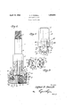
Figure 1 is' an elevation partially in vertical section of the drilling bit.
Figure 2 is a fragmentary elevation at right angles to Figure 1 and Figure 3 is a section on the line 33 of I Figure 1, the ends of the head and pins being removed.
Referring to the drawings, the drilling bit is illustrated as comprising a plurality of rolling cutters 2 rotatably mounted by a head 3, which head in turn is rotatably mounted upon a driving member 4. The drive mefn- 1928. Serial No.283,219;
fluid will be discharged between the adjacent faces of the rolling cutters.
The driving member 4 is indicated as having an enlargement 7 at its lower end which serves as a means for holding the head 3 of the bit to the driving member. The driving member is further shown as provided with a plurality of depending pins 8 which may be integral with the head 7, which depending pins 8 serve as means for forming a gear connection between the head 7 of the driving member 4 and the roller cutters 2. The head 7 of the driving member 4 is also preferably provided with a recess 9 at its lower end, to provide clearance between it and the outer cutting edges of the cutting rollers 2. The pins 8 of the driving'member are also indicated at 10 as cut away to clear the back surface of the cutting rollers'2.
The cutting rollers of the drilling bit are preferably made with conical or frusto-conical cutting faces 11 which may be cut in any preferred or desired manner into teeth or suitable cutting ridges or projections, and the cutting rollers 2 are disposed on axes which converge substantially at the axis of the drilling bit. The axes of the cutting rollers 2 are preferably at about 45 with the horizontal plane and the preferred form of the bitineludes two diametrically opposite cutting rollers. The cutting rollers 2 are further provided at their rear ends with recesses 12 for receiving pins 13 and bushings 14 which serve as a means for rotatably mounting the cutters 2 upon the head 3. The rear faces of the cutting rollers 2 are indicated as proil'ded with a tapered surface 15.0f general frustro-conical shape, the apex of which is in the opposite direction to that.of the apex of the cutting face of the cutters. The base of the rear frusto-conical portion of the cutter 2 is provided with gear teeth 16, shaped to coact with the gear pins 8 on the driving member 4 and shaped so that in operating position, the tops of said gear teeth provide bearing faces engaging the bottom of the head 7 of the drive member 4, while the bottoms of the rooves formed by the teeth form additional earing surfaces engaging the bottoms of the gear pins 8. The taper of the rear face of the cutters 2 and of the top faces of the gear teeth 16 are preferably such that these bearing faces are substantially horizontal when they are rotated to the upper position.
The relationship between the taper of the crushing surfaces of the cutters and the taper of the driving or thrust surfaces of the cutters may also be described by the specification that the generating line of the frusto-conical crushing surface of the cone is parallel to the generating line of the thrust or driving surface of the cone which is on the opposite side of the axis in any section taken through the axis of the cutter. Thus in Figure 1 the generating line of the driving or thrust surface of the cone which corresponds to the section line 33 is parallel to the generating line AA of the crushing surface of the cone which is on the opposite side of the cutter axis.
The drive member 4 and its gear pins 8, and the cutting rollers 2, preferably, are so proportioned relative to each other, that the transfer of pressure from the drive member 4 through the bearing faces described, to the roller 2 take place at points vertically aligned with substantially the midpoint of the cutting faces of the cutters 2 at the bottom of the cutters. By this arrangement of the parts, it will be seen that the drilling pressure is transferred directly from the drive member 4 over the center of the cutting operations without the drilling pressure passing through the pins 13 and bushings 14 rotatably mounting the cutters.
The head 3 of the drilling bit has a neck 17 having a running fit with the driving member 4 above the head 7 of said drive member and the head 3 has its bore enlarged as indicated at 18, to form a running fit with the head 7 of the drive member. The enlargement 18 of the bore of the head 3 is made of sufficient length, as to clear slightly the top of the enlargement 7 of the drive member. Head 3 forms two lugs 19 and 20, having upwardly tapering inner faces against which the rolling cutters 2 bear and the lugs 19 and 20 have openings 21 and 22 receiving the pins13 which mount the cutters 2. There is also preferably provided lock pins 23 and 24 for locking the bearing pins 13 to the head 3.
In operation of the bit herein described, the drive member 4 is continuously rotated under. a downward pressure from 4 the drill pipe while a flushing fluid is continuously circulated through the passage 6. The gear connection between the drive member 4 and the roller cutters 2 synchronizes the rotation of the cutters and causes the roller cutters 2 to planetate in the bottom of the well hole rolling upon the formation, so that the cutting teeth, ridges or projections thereof, penetrate the rock formation. In the drilling operations, due to the direct imposition of both the turning torque and vertical load upon the cutters 2, the bushings 14 and bearing pins 13 of the cutters are relieved from any material stresses so that the wear takes place almost exclusively upon the cutting faces and projections of the cutters. In operation, this is found to prevent the cutters from wearing the pins so that the cutters will be moved into interlocking position and also further to prevent any twisting or bending of the supporting pins and further, to prevent the cutters from being moved inwardly and changing the diameter of the well bore. It is further found in operation, that a less torque is placed on the drill pipe with the bit of the present invention than is customary in previous forms of bits. decreasing the hazards of twisting the bit off in the well hole.
Another important advantage of the present invention resides in the fact that due to the direct imposition of torque and vertical load on the cutters, a greater vertical load may be applied to it in operation than is customary.
A bit of the present invention is found to drill more rapidly in a well hole because of the fact that greater vertical pressure may be placed on the bit and a slower speed of rotation of the cutters employed, which results in a more rapid rate of drilling with less wear of the drilling cutters.
While the form of drilling bit herein described is well adapted for carrying out the objects of the present invention, it is understood that various modifications and changes may be made without departing from the principles of the invention and the invention includes all such changes and modifications as come Within the scope of the appended claims.
I claim:
1. A drilling bit comprising: a drive member; roller cutters; a head rotatably mounted on said drive member and rotatably mounting said roller cutters; means for driving said roller cutters with the rotation of said drive member;-and means for imposing vertical load directly from the drive member to each of said roller. cutters at a point vertically aligned with the approximate center of the portions of the cutting faces of the cutters occupying the lower position.
2. A drilling bit comprising: a drive and supporting member; a plurality of cutting rollers including cutting teeth andseparate gear teeth; a head swiveled upon said drive member and revolvably mounting said cutting rollers; and gear means carried by said drive member and engaging the gear teeth of said cutting rollers.
3. A drilling bit comprising: a drive member; a plurality of cutting rollers, having cutting teeth and separate gear teeth; a head swivcled upon said drive member and revolvably mounting said cutting rollers; and gear means between said drive member and said cutting rollers, said gear means being arranged to serve as a means for transferring vertical load from the drive member to the cutters.
4. A drilling bit comprising: a drive member; a plurality of cutting rollers; a head swiveled upon said drive member and revolvably mounting said cutting rollers; and gear means between said drive member and said cutting rollers, said cutting rollers having thrust receiving surfaces and cutting surfaces, said surface being arranged so that the uppermost portions of the thrust receiving surface are at all t mes disposed directly above the lowermost portions ofthe cutting surface, said gear means being thus arranged to serve as means for transferring vertical load to said cutting rollers as well as turning torque.
5. A drilling bit comprising: a head; cutting rollers having conical cutting faces. the axes of which substantially converge at the axis of the bit, said cutting rollers being revolvably mounted by said head. said cutting rollers having rear faces angled relative to the conical cutting faces, the rear faces of said cutting rollers forming bearing surfaces a drive member extending through said head and engaging said bearing surfaces for directly transferring vertical load to said cutting rollers; and gear means between said cutting rollers and said drive member.
6. A drilling bit comprising: a head; cutting rollers rotatably mounted by said head on axes converging substantially at the axis of the bit, the cutting rollers having frustoconical shaped cutting faces and having rear bearing faces angled relative to the cutting faces; a drive member on which said head is swiveled; and gear means between saiddrive member and said cutters, said gear means operating to transfer the vertical load directly from the drive member to the cutting rollers in vertical alignment with the approximate center of the lower portions of the cutting surfaces of the rollers which occupy momentarily the cutting'positions.
7. A cutter for a drilling bit having a conical cutting face at one end end a conical hearing face on the other end, the apex of the cutting face being towards the forward end of the cutter and the apex of the bearing face being towards the rear end of the cutter, said bearing face including gear teeth.
8. A drilling bit comprising: a drive mem ber having an axial water course; a head swlveled on the drive member; cutting rollers rotatablymounted on said head in position to have their cutting faces cleaned by fluid from said passages; and means for directly transferring vertical load and torque from the drive member to the cutting rollers.
9. A well drilling bit comprising: a plurality of cutting members; a head upon which said members are rotatably mounted; a main rotatable driving and supporting member upon which said head is swivelled: means for driving said cutting members with the rotation of said driving and supporting member; and means for transmitting vertical load directly from the main driving and supporting member to said cutters.
' 10. A rolling cutter for a well drilling bit, j
said rolling cutter having a main crushing surface with crushing projections and an integral thrust receiving surface including gear teeth, said surfaces being arranged so that the uppermost portions of the thrust receiving surface will at all times be disposed directly above the lowermost portions of the cutting surface.
11. A rolling cutter for a well drilling bit, said rolling cutter having a conical cutting and crushing surface at one end having gearlike crushing projections shaped so that when said cutting surface is moved against a formation with a true rolling motion it will be geared to said formation, the rolling cutter having a conical thrust receiving surface at the other end which surface includes gear teeth, the apex of the conical thrust receiving surface being disposed at the opposite end of the cutter from the apex of the cutting surface, said surfaces being arranged so that the uppermost portions of the thrust receiving surface will at all times be disposed directly gbove the lower portions of the cutting surace. 12. A drilling bit comprising: a drive member; a head; cutting rollers rotatably mounted by said head on axes converging substantially at the axis of the bit, said head being rotatable and axially slidable on said drive member; bearing surfaces on said cutting rollers, said drive member engaging said bearing surfaces for directly transferring vertical load to said cutting rollers; and gear means between said cutting rollers and said drive member.
13. A rotary well drilling bit comprising: a driving shank; a head rotatable about said driving shank; cutters rotatably mounted on said head and adapted to roll on the formation to be drilled; and gear means connecting said cutters with said driving shank operating as load'transmitting means, said cutters having frusto-conical crushing surfaces and frusto-conical thrust surfaces on opposed ends thereof, the generating line of the conical crushing surface being parallel to the generating line of the conical thrust surface on the opposite side of the cutter axes.
14. A rotary well drilling bit comprising: a driving shank; a head rotatable about said driving shank; cutting rollers rotatably mounted on said head; means for driving said cutting rollers with the rotation of said driving shank; and means for imposing vertical load from said driving shank directly upon said cutting rollers at a point vertically aligned with approximately the center of the crushing surfaces of said cutting rollers at the bottom of the .drilling bit.
15. A rotary well drilling bit comprising: a driving shank; a head rotatable about said driving shank; rolling cutters rotatably mounted on said head; and means for directly connecting said driving shank and said rolling cutters operative for transmitting the load vertically and drilling torque directly from said driving shank to said rolling cutters.
16. A rotary well drilling bit comprising: a driving shank; a head rotatable about said driving shank; rolling cutters rotatably mounted on said head; and gear means connecting said driving shank and said rolling cutters, said gear means being arranged to serve as vertical load transmitting means between said driving shank and said cutters and being arranged to transmit vertical load to said cutters at points vertically aligned with approximately the center of the crushing surfaces of said cutters which occupy the cutting position.
17. A rotary well drilling bit comprising: a driving shank; a head rotatable about said driving shank; rolling cutters rotatably mounted on said head, said cutters having conical crushing surfaces and axes of rotation substantially converging at the axis of the bit, said cutters having rear conical thrust receiving surfaces; and driving means connecting said driving shank with said rear thrust receiving surfaces of said cutters for directly transmitting vertical load and drilling torque to said rolling cutters.
18. A rotary well drilling bit comprising:
a driving shank; a head rotatable about said driving shank; rolling cutters rotatably mounted on said head, said rolling cutters having conical cutting faces, the axes of rotation of said cutters substantially converging at the axis of the bit, the rear faces of said rolling cutters forming bearing surfaces; and gear means connecting said driving shank with said rear faces of sald cutting rollers, thereby to transmit directly vertical load and drilling torque from said driving shank to said cutting rollers.
19. A rolling cutter'for a rotary well drilling bit, said cutter having a frusto-conical crushing surface with cutting projections and an approximately frusto-conical driving surface, the apices of such frusto cones being on opposite ends of the cutter, the frustoconifial driving surface having recessed gear teet 20. A rolling cutter for a well drilling bit, said cutter having a frusto-oonical cutting surface with cutting projections, a frustoconical drive surface integral with the crushing surface, and having its apex at the opposite end of the cutter, the generating line of the crushing surface being parallel to the generatingline of the driving surface on opposite sides in any section through the axis of the cutter.
21. In a drill: a substantially conical roller having longitudinal cutting teeth and separate driving teeth; and drive means on said drill meshing with said driving teeth.
22. In a rotary bit of the character described, the combination of: a head; an inclined cutter pivoted on said head, said outter having an axis intersecting the axis of rotation of said bit; and means rotatable axially of said bit and engaging said cutter to take up non-axial thrust upon said cutter.
23. In a rotary bit of the character described, the combination of: a head; a cutter pivoted on said head, said cutter having cutting teeth and separate driving teeth; and means engagin said drivin teeth adapted to synchronize t e rotation 0 said cutter and take up non-axial thrust thereon.
24:. In a rotary bit of the character described, the combination of: a head; a plurality of cutters pivoted on said head; said cutters having cutting teeth and separate driving teeth; and means bridgin said driving teeth adapted to synchronize t e rotation of said cutters and take up non-axial thrust imgosed thereon.
igned at Los Angeles, Calif, this 14th day of May, 1928.
ALFRED F. POWELL.
Priority Applications (1)
| Application Number | Priority Date | Filing Date | Title |
|---|---|---|---|
| US283219A US1854623A (en) | 1928-06-06 | 1928-06-06 | Rock drilling bit |
Applications Claiming Priority (1)
| Application Number | Priority Date | Filing Date | Title |
|---|---|---|---|
| US283219A US1854623A (en) | 1928-06-06 | 1928-06-06 | Rock drilling bit |
Publications (1)
| Publication Number | Publication Date |
|---|---|
| US1854623A true US1854623A (en) | 1932-04-19 |
Family
ID=23085061
Family Applications (1)
| Application Number | Title | Priority Date | Filing Date |
|---|---|---|---|
| US283219A Expired - Lifetime US1854623A (en) | 1928-06-06 | 1928-06-06 | Rock drilling bit |
Country Status (1)
| Country | Link |
|---|---|
| US (1) | US1854623A (en) |
Cited By (3)
| Publication number | Priority date | Publication date | Assignee | Title |
|---|---|---|---|---|
| US2763469A (en) * | 1952-01-01 | 1956-09-18 | Cementation Co Ltd | Rotary rock drills |
| US3250337A (en) * | 1963-10-29 | 1966-05-10 | Max J Demo | Rotary shock wave drill bit |
| US3913686A (en) * | 1974-03-18 | 1975-10-21 | Halliburton Co | Method and apparatus for preventing and detecting rotary drill bit failure |
-
1928
- 1928-06-06 US US283219A patent/US1854623A/en not_active Expired - Lifetime
Cited By (3)
| Publication number | Priority date | Publication date | Assignee | Title |
|---|---|---|---|---|
| US2763469A (en) * | 1952-01-01 | 1956-09-18 | Cementation Co Ltd | Rotary rock drills |
| US3250337A (en) * | 1963-10-29 | 1966-05-10 | Max J Demo | Rotary shock wave drill bit |
| US3913686A (en) * | 1974-03-18 | 1975-10-21 | Halliburton Co | Method and apparatus for preventing and detecting rotary drill bit failure |
Similar Documents
| Publication | Publication Date | Title |
|---|---|---|
| US2124414A (en) | Well drilling bit | |
| USRE23416E (en) | Drill | |
| US2244537A (en) | Well drilling bit | |
| US2148372A (en) | Offset tricone bit | |
| US1388424A (en) | Rotary bit | |
| US7090034B2 (en) | Reamer having toroidal crusher body and method of use | |
| US2363202A (en) | Teeth for drill cutters | |
| US4154312A (en) | Drill bit with single cutting head | |
| US6786288B2 (en) | Cutting structure for roller cone drill bits | |
| US1750953A (en) | Rotary reamer | |
| RU2394145C1 (en) | Drilling cone bit with central flush | |
| CN103541660A (en) | Composite type eccentric one-cone bit | |
| US1854623A (en) | Rock drilling bit | |
| US1703390A (en) | Drill | |
| US1905066A (en) | Rolling drill cutter | |
| US1885085A (en) | Rock drill | |
| US2009742A (en) | Face bit | |
| WO2003091531A1 (en) | A roller bit with a journal pin offset from the central axis thereof | |
| AU2002253951B2 (en) | Reamer having toroidal cutter body and method of use | |
| US2039551A (en) | Rotary bit | |
| US1778966A (en) | Roller bit | |
| AU2002253951A1 (en) | Reamer having toroidal cutter body and method of use | |
| US1983316A (en) | Three-cone bit | |
| US2133022A (en) | Rotary drill bit | |
| US1854624A (en) | Well drilling bit |