US1854624A - Well drilling bit - Google Patents
Well drilling bit Download PDFInfo
- Publication number
- US1854624A US1854624A US442154A US44215430A US1854624A US 1854624 A US1854624 A US 1854624A US 442154 A US442154 A US 442154A US 44215430 A US44215430 A US 44215430A US 1854624 A US1854624 A US 1854624A
- Authority
- US
- United States
- Prior art keywords
- cutters
- driving
- head
- bit
- shank
- Prior art date
- Legal status (The legal status is an assumption and is not a legal conclusion. Google has not performed a legal analysis and makes no representation as to the accuracy of the status listed.)
- Expired - Lifetime
Links
- 238000005553 drilling Methods 0.000 title description 46
- 238000005096 rolling process Methods 0.000 description 26
- 230000015572 biosynthetic process Effects 0.000 description 12
- 238000005755 formation reaction Methods 0.000 description 12
- 230000036346 tooth eruption Effects 0.000 description 4
- 238000012937 correction Methods 0.000 description 3
- 239000012530 fluid Substances 0.000 description 3
- 239000011435 rock Substances 0.000 description 3
- 238000012856 packing Methods 0.000 description 2
- 241001176357 Imber Species 0.000 description 1
- 240000007049 Juglans regia Species 0.000 description 1
- 235000009496 Juglans regia Nutrition 0.000 description 1
- 230000003247 decreasing effect Effects 0.000 description 1
- 230000000694 effects Effects 0.000 description 1
- 239000000835 fiber Substances 0.000 description 1
- 238000011010 flushing procedure Methods 0.000 description 1
- 239000000314 lubricant Substances 0.000 description 1
- 239000002184 metal Substances 0.000 description 1
- 238000000034 method Methods 0.000 description 1
- 235000014571 nuts Nutrition 0.000 description 1
- 230000000149 penetrating effect Effects 0.000 description 1
- 229920000136 polysorbate Polymers 0.000 description 1
- 238000004513 sizing Methods 0.000 description 1
- 235000020234 walnut Nutrition 0.000 description 1
- XLYOFNOQVPJJNP-UHFFFAOYSA-N water Substances O XLYOFNOQVPJJNP-UHFFFAOYSA-N 0.000 description 1
Images

Classifications
-
- E—FIXED CONSTRUCTIONS
- E21—EARTH OR ROCK DRILLING; MINING
- E21B—EARTH OR ROCK DRILLING; OBTAINING OIL, GAS, WATER, SOLUBLE OR MELTABLE MATERIALS OR A SLURRY OF MINERALS FROM WELLS
- E21B10/00—Drill bits
- E21B10/08—Roller bits
-
- E—FIXED CONSTRUCTIONS
- E21—EARTH OR ROCK DRILLING; MINING
- E21B—EARTH OR ROCK DRILLING; OBTAINING OIL, GAS, WATER, SOLUBLE OR MELTABLE MATERIALS OR A SLURRY OF MINERALS FROM WELLS
- E21B10/00—Drill bits
- E21B10/08—Roller bits
- E21B10/18—Roller bits characterised by conduits or nozzles for drilling fluids
-
- E—FIXED CONSTRUCTIONS
- E21—EARTH OR ROCK DRILLING; MINING
- E21B—EARTH OR ROCK DRILLING; OBTAINING OIL, GAS, WATER, SOLUBLE OR MELTABLE MATERIALS OR A SLURRY OF MINERALS FROM WELLS
- E21B10/00—Drill bits
- E21B10/08—Roller bits
- E21B10/20—Roller bits characterised by detachable or adjustable parts, e.g. legs or axles
-
- E—FIXED CONSTRUCTIONS
- E21—EARTH OR ROCK DRILLING; MINING
- E21B—EARTH OR ROCK DRILLING; OBTAINING OIL, GAS, WATER, SOLUBLE OR MELTABLE MATERIALS OR A SLURRY OF MINERALS FROM WELLS
- E21B10/00—Drill bits
- E21B10/08—Roller bits
- E21B10/22—Roller bits characterised by bearing, lubrication or sealing details
-
- E—FIXED CONSTRUCTIONS
- E21—EARTH OR ROCK DRILLING; MINING
- E21B—EARTH OR ROCK DRILLING; OBTAINING OIL, GAS, WATER, SOLUBLE OR MELTABLE MATERIALS OR A SLURRY OF MINERALS FROM WELLS
- E21B4/00—Drives for drilling, used in the borehole
- E21B4/006—Mechanical motion converting means, e.g. reduction gearings
Definitions
- This invention relates to a well drilling bit and refers particularly to the type of well drilling bit employed in drilling through hard rocks by the hydraulic rotary method.
- An object of the invention is to provide a drilling bit of the class intended for drilling through hard or semi-hard rock by means of rolling cutters in which there is provided a means for imposing the load from the drill pipe directly upon the rolling cutters, whereby the pins and bushings employed for revolvably mounting the rolling cutters are for theoretical purposes, entirely relieved from this pressure.
- Another object of the resent invention is to provide means for lrectly driving the rolling cutters of the drill bit from the rotation of the drill pipe so that the drilling torque is transferred directly from the drill pipe to the cutters, rather than being transmitted from the drill pipe to the rolling cutters through the pins and bushings or p other means.
- a further object of the present invention is to provide a drill bit with a rotatably mounted head which is normally supported upon the cutters.
- a further object of the .present invention resides in the provision of means for locking the driving gear means against torque, while permitting rotation with the drive shank.
- a further object of the presentinvention is to provide a driving gear in the form of a disc having faces for locking the disc against torque, Awhile permitting axial motion of the driving gear.
- a further object of the present invention is to provide a drill bit in which with a given rotation of the drill pipe, the rotation of the cutters at the bottom of the well and the p anetary movement of the cutters, is materially reduced when compared with other bits.
- a further object of the present invention is to provide a drilling bit of the above type in which the parts subject to rapid wear are not integral with the main body and are therefore capable of being replaced 4at low cost.
- a planetary rate of rotation of the rolling cutters of approximately 20 R. P. M. is the optimum rate' to produce the maximumfprogress of drilling the formation; whereas, to transmit the proper power through the drill pipe, a speed of approximately 40 R. P. M. is desirable.
- the bit of the present invention is designed to permit the drill pipe to rotate at the desired speed to transmit the proper ower for drilling operations with a low ber stress, and included means by which this speedr of rotation is reduced so that the rolling cutters have a planetary rotation suiliciently low to give the greatest progress in drilling with the most suitable load on the rolling cutters.
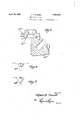
- Figure 1 is an elevation mainly in vertical section of the drilling bit.
- Figure 2 is an elevation of the bit illustrated in Figure 1 with the cutters removed.
- Figure 3 is a perspective of the removable drive gear employed in the well drilling bit of Figuresl and 2.
- Figure 4 is a fragmentary view illustrating'the manner of wear of a cutter tooth orl projection of the present invention.
- Figure 5 is a similar view showing the manner of wear generally experienced with the cutter teeth or projections heretofore generally used.
- Figure 6 is a diagrammatic illustration o f a modified form of cutter and drive gear.
- the drilling bit is illustrated as comprising a tubular central supporting and power transmitting or driving reamer shank 30 which is provided with a tapered pin 31 at its upper end and which serves as a means by which the drilling .bit may be attached to a string of drill pipe and rotated at the bottom of a well hole.
- the upper part of said member 30 carries a plurality of reaming rollers 32 for straightening and reaming the hole drilled by the main cutters of the bit. These reaming rollers 32 are shown as mounted within recesses 33 in the member 30 on the reamer pins 34.
- reamer pins 34 there are provided longitudinal recesses 35 by which the pins may be inserted, and 36 indicates dowel pins for locking the reamer pins 34 in place. Openings 37 are indicated at the lower end of the pins 34 through which a tool may be inserted for knocking out the pins 34 when it is desired to replace the reaming cutter 32.
- the lower part of the central supporting I and power transmitting member 30 is reduced as indicated at 38, forming a downturned annular shoulder 39.
- the bore 42 of the member 30 provides an axial passage through which the flushing fluid may be supplied to the cutters of the bit.
- Said 'pac ing preferably comprises a rubber ring 46 which in operation is urged outwardly against the head 43 by pressure of drilling fluid entering the back of said ring through ducts 47.
- annular groove 48 which receives the ends of the head retaining pins 49 which are inserted in openings in the head 43 and extend into the bore of said head suiciently to engage the groove 48and prevent the head parting from the power transmitting member in the operations of inserting and removing the bit from the well hole.
- pins are held in place by check nuts 51 threaded in said openings in the head 43.
- the lower end of the head is provided with two diametrically opposed cutter shafts 52 which extend downwardly and inwardly into the space below the head and reamer shank 30. These shafts 52 are held in place by lock screws 53 passing through the upper ends of the shafts 52 and screwed into threaded openings in the head 43. On shafts 52 are mounted bushings 54 which are provided with recesses 55 at their inner ends which lit over bosses 56 on the end of the head for centering the bushings. shafts 52 are provided with bores 57 which serve as lubricant holding chambers.
- frustoconical rolling cutters 58 Upon the bushings 54 are mounted frustoconical rolling cutters 58. These rolling cutters 58 comprise, in integral form, two frusto-conical cones united at their bases, one of the frusto-conical cones being provided with cutting teeth 59 while the other of said cones is formed with gear teeth 60.
- the cutting teeth 59 of the cones and the shape of the cones are so designed that when the cones are given a planetary rotation by revolution of the reamer shank 30 around the axis of the well bore, the cutting teeth 59 will roll against the formation at the bottom of the bore hole, cutting ridges thereon, whereby the rolling cutters 58 become in operation meshed to the bottom of the bore hole.
- cutters 58 are additionally provided with annular grooves 61 which serve to receive rings The outer ends of the of metal 62 serving to lock the cutters from movement axially with respect to bushings 54.
- Each of the cutters 58 is provided with radial openings 63 through ⁇ whlch a tool may be inserted to engage a hole 64 in the bushing 54, whereby the bushing and cutters may be as a unit, be assembled upon-the shafts 52.
- a driving gear 65 At the lower end of the power transmitting member 30 there is a driving gear 65, lillustrated in Fig. 3, the lower portion of which is a disc having a bevelled periphery 66 fitting the bevel 40 on the lower end of the member 30 and is also provided with a bevelled rectangular boss 67 fitting the bevelled rectangular socket 41 in the member 30.
- An axial orifice 68 with an enlarged entrance is provided in the driving gear 63 to permit the passage of drilling fluid from the bore 42 therethrough.
- Gear teeth 69 are provided on the lower face of the driving gear and are adapted to mesh with the gear teeth 60 on the rear frusto cones of the cutters 58.
- 70 indicates a packing ring engaging the lower end of the drive member 30 and held in the annular recess of the head 43.
- The-drive gear 65, driving member 30 and head 43 are so arranged' and related that the engagement between the teeth of the driving gear and cutters 58 takes place at a point which is approximately in the middle of the cutting teeth 59 at the bottom of the cutter.
- This permits the vertical -load which, in operation is imposed upon the drill bit from the weight of the drill pipe connected therewith, to be transmitted directly from the drive member 30 to the cutters 58 centrally over the cutting zone without this weight having to be transmitted through pins and bushings connecting the cutter with the head 43.
- this imposition ofthe load from the drive member 30 to the cutters 58 will substantially prevent any wear on the bushings or bore of the cones.
- the outward thrust of the gear operates to spread the cutters 58 in such manner as to compensate for any wear on the bushings and maintain the cutters in position where they cut the same size or larger bore hole, the weight of head 43 being normally supported upon the cutters 58.
- the rotation of theldrive member 30 is imparted directly to the rolling cutters 58.
- hese rollin cutters 58 cut into the formation at the ottom of the well and mesh themselves thereto.
- the rotation of the cutters 58 then effects a definite rotation of the head 43.
- the motion of the head 43 is approximately one-half of that of the drive member 30, although any desired ratio may be attained b proper sizing of the gear.
- Another advantage of the present invention resides in the fact that the two cutters are connected to gearing means which insures each cutter nding a proper fresh point in the formation to penetrate. If the cutters are made with anequal number of teeth and mounted loosely upon the bit, each cutter will merely follow around in the same tooth imprints produced by the previous cutter and little, if any, cutting action will be effected. By proper proportioning of the teeth on the gears with the bit of the present invention the teeth on each cutter will strike the formation between the imprints of the teeth of the other cutter.
- the rear side 590 of the worn projection is slightly concave while both sides are worn down from the original shape of the projection, as indicated by the dotted lines 59d.
- the worn tooth however, it will be noted, is fully as sharp as the original tooth.
- Figure 5 there is illustrated in full lines 59e the shape of a worn tooth of a frustoconical cutter operating on the type of bit previously employed as compared with the original shape of such tooth indicated by the dotted lines 59f.
- the type of bit which wears the teeth shown in Figure 5 drags thecones around and is subject to slippage while the bit of this invention drives the cones around and thereby excludes slippage.
- While the form of drilling bit herein de cutters being provided with gear teeth; gear means provided on said driving shank engaging said rolling cutters, said rolling cutters having axes of rotation substantially converging with the axis of the bit and being provided with crushing surfaces and cutting projections adapted to roll on the formatlon at the bottom of the Well bore, said gear means being operative to transmit the vertical load directly from said driving shank to said cutting rollers; and anti-friction bearing means between said head and said driving shank normally inoperative but adapted upon wear of the gear for recelving the vertical load.
- a rotary well drilling bit comprising: a driving shank; a head rotatable about said driving shank; rolling cutters rotatably mounted on said head; drivfg means connecting said driving shank with said rolling cutters, the longitudinal load being transmitted from said driving shank directly upon said cutter, said head being normally tion bearing means normally in an inoperative position and adapted following predetermined wear to receive the load from said driving shank and transmit the same to said head.
- a driving gear for a rotary well drilling bit' comprising: a disc with a bevelled perimeter and a bevelled rectangular boss on one side of said disc; gear teeth on the opposite face of said disc; and 'w alls forming an axial orifice through saiddisc.
- a driving gear for a well drilling bit comprising: a disc having faces for locking the disc against torque while permitting axial motion of the driving gear; gear teeth on the lower surface of the disc; and walls forming projections from the disc, and an axial water course through the drive gear.
- a driving gear for a well drilling bit comprising: a disc having a rectangular boss and anti-fric-v at one side and gear teeth on the opposite side, the gear teeth being bevelled back to- -Wards the center; and Walls forming an axial orifice through the disc and gear teeth, said axial orifice having an expanding throat.
- a rotary well drilling bit comprising: a driving shank; a head rotatable about said driving shank; cutters rotatably mounted on said head and adapted to roll on the formation being drilled, said cutters having frustoconical cutting surfaces on one end and approximately frusto-conical driving surfaces on the opposite end; a disc arranged between said driving shank and said cutters; and gear teeth on the lower face of said disc engaging said driving surfaces for driving said cutters.
- a rotary well drilling bit comprising: a driving shank; a head rotatable about said driving shank; cutters rotatably mounted on said head and having oppositely disposed cutting and driving surfaces; a disc arranged between said driving shank and said cutters; means for locking said disc against torque while permitting rotation with said drive shank; and gear teeth on the lower surface of said disc engageable with said driving surfaces for driving said cutters.
- a vrotary well drilling bitI comprising: a driving shank providing a socket; a head rotatableabout said driving shank; cutters rotatably mounted on said head and adapted to roll on the formation to be drilled; and a power transmitting member removably positioned in said socket operative to turn said cutters about their axes directly with the rotation of said driving shank when said cutters are engaged with the formation being drilled, said power transmitting member operating to impose vertical loaddirectly from said driving shank to each of said cutters at apoint vertically aligned with the approximate center of the position of the cutting faces of the cutters occupying the lower position.
- a rotary well drilling bit comprising: a. driving shank providing a socket; a head rotatable about said driving shank; cutters rotatably mounted on said head and adapted to roll on the formation to be drilled; and gear means removably positioned in said socket connecting said cutters with said driving shank, and operating as load transmitting means, said cutters having frusto-conical crushing surfaces and frusto-conical thrust surfaces on opposite ends thereof, the generating line of the conical crushing surface being parallel to the generating line of the conical thrust surface on t-he other side of the cutter axes.
- a rotary well drilling bit comprising: a driving shank providing a socket; a head rotatable about said driving shank; cutting rollers rotatably mounted on said head; a gear member removably positioned in said socket for drivingr said cutting rollers with the rotation of said driving shank; and means tween said insert member and the walls of for imposing vertical load from said driving said socket whereby said insert member takes shank directly upon said cutting rollers at a the vertical thrust imposed upon said conical point vertically aligned with approximately cutting members.
- a rotary well drilling bit comprising: a driving shank providing a socket; a head rotatable about said driving shank; rollin cutters rotatably mounted on said head; an gear means removably positioned in said socket, said gear means connecting said driving shank and said rolling cutters and being arranged to transmit vertical load to said cutters at pointsvertically aligned with ap proximately the center of the crushing surfaces of said cutters which occupy the cutting position. 12.
- a rotary well drilling bit comprising: a driving shank providing ⁇ a socket; a head rotatable about said driving shank; rolling cutters rotatably mounted on said head, said cutters having conical crushing surfaces and axes of rotation substantially converging at the axis -of the bit and rear conical thrust receiving surfaces; and driving means removably positioned in said socket for connecting said driving shank with said rear thrust receiving surfaces of said cutters and directly transmitting vertical load and drilling torque v to said rolling cutters.
- a rotary well drilling bit comprising:
- cutters rotatably mounted on said head, said cutters'having conical crushing surfaces and axes of rotation substantially converging at the axis of the bit, said cutters having rear conical thrust receiving surfaces; and driving means removably positioned in said socket, said driving means connecting said driving shank with said rear thrust receiving surfaces of said cutters for directly transmitting vertical load and drilling torque to said rolling cutters.
- a rotary well drilling bit comprising: a driving shank; a head rotatable about said driving shank; an' insert member-in said driving shank having a substantially flat lower surface; teeth formed insaid lower surface; and a pair of conical cutting members rotatably mounted on said head entirely below said insert member and providing teeth engaging said teeth in said lower surface whereby said insert member takes the vertical thrust imbers rotatably mounted on said head; walls -:forming a socket in said driving shank: an insert member removably positioned in said 6
Landscapes
- Engineering & Computer Science (AREA)
- Life Sciences & Earth Sciences (AREA)
- Geology (AREA)
- Mining & Mineral Resources (AREA)
- Mechanical Engineering (AREA)
- Physics & Mathematics (AREA)
- Environmental & Geological Engineering (AREA)
- Fluid Mechanics (AREA)
- General Life Sciences & Earth Sciences (AREA)
- Geochemistry & Mineralogy (AREA)
- Earth Drilling (AREA)
Description
April 19, 1932.
A. lF..F"(DWELL WELL DRILLING BIT-y 2 Smets-sheet Filed April 7 1930 will ill i.
Jy J7 63 f2 'Patented Apr. 19, 1932 Ulm'rel` STATES ALFRED F. POWELL, or WALNUT PARK, cALIronmA WELL DRILLING BIT pplication led April 7, 1930. Serial N'o. 442,154.
This invention relates to a well drilling bit and refers particularly to the type of well drilling bit employed in drilling through hard rocks by the hydraulic rotary method.
This invention is a continuation in part of rollin my copending application Serial N o. 283,219, filed June 6, 1928.
An object of the invention is to provide a drilling bit of the class intended for drilling through hard or semi-hard rock by means of rolling cutters in which there is provided a means for imposing the load from the drill pipe directly upon the rolling cutters, whereby the pins and bushings employed for revolvably mounting the rolling cutters are for theoretical purposes, entirely relieved from this pressure.
Another object of the resent invention is to provide means for lrectly driving the rolling cutters of the drill bit from the rotation of the drill pipe so that the drilling torque is transferred directly from the drill pipe to the cutters, rather than being transmitted from the drill pipe to the rolling cutters through the pins and bushings or p other means.
A further object of the present invention is to providea drill bit with a rotatably mounted head which is normally supported upon the cutters.
A further object of the .present invention resides in the provision of means for locking the driving gear means against torque, while permitting rotation with the drive shank.
A further object of the presentinvention is to provide a driving gear in the form of a disc having faces for locking the disc against torque, Awhile permitting axial motion of the driving gear.
A further object of the present invention is to provide a drill bit in which with a given rotation of the drill pipe, the rotation of the cutters at the bottom of the well and the p anetary movement of the cutters, is materially reduced when compared with other bits.
A further object of the present invention is to provide a drilling bit of the above type in which the parts subject to rapid wear are not integral with the main body and are therefore capable of being replaced 4at low cost.
It is well known, that the power that can be transmitted through a drill ipe with a given fiber stress or torque is irectly proportional with the rate of rotation of the pipe. Therefore, the higher the speed of rotation the greaterwill be the power that can be transmitted through the drill pipe to the rolling cutters and as a result the greater the amount of work performed by the rolling cutters in penetrating and clisintegrating the formation in boring the well.
Experience teaches that in practice due to the nature of the work to be done by the rolling cutters, there is an optimum speed of the cutters to give the greatest progress in drilling with the most suitable load on the cutters. This optimum speed is found in practice to be much lower than the desired rate of rotation of the drill pipe to transmit with reasonable strain the necessary power to the rolling cutters.
As an example, in drilling certain formations it is found that a planetary rate of rotation of the rolling cutters of approximately 20 R. P. M. is the optimum rate' to produce the maximumfprogress of drilling the formation; whereas, to transmit the proper power through the drill pipe, a speed of approximately 40 R. P. M. is desirable. The bit of the present invention is designed to permit the drill pipe to rotate at the desired speed to transmit the proper ower for drilling operations with a low ber stress, and included means by which this speedr of rotation is reduced so that the rolling cutters have a planetary rotation suiliciently low to give the greatest progress in drilling with the most suitable load on the rolling cutters.
With the well drilling bit of the present invention it isfound in operation that the drilling pipe is subjected to less torsional stress than with the bits heretofore employed, thereby decreasing the hazard of a twist-off ing cutters and a greater speed of drilling attained.
' ofthe drill pipe in the bore hole. At the' same time more power is supplied tothe roll- In drillin wells by the drilling bits which have hereto ore been in common use the abrasive action between the well formation and the cutters or teeth of the cutters has generally resulted in the cutters or teeth of the cutters becoming dull with use. With the well drilling bit of the present invention it is found in operation that the cutters or teeth of the cutters are subject to wear in such a manner as to maintain the teeth as sharp or sharper than they are on the new cutters, with the result that the bit continues to drill rapidly for a long period of operation.
Various further objects and advantages of the present invention will be apparent from the description of the preferred forms or examples of a drilling bit embodying the invention. For this purpose reference is made to the accompanying drawings in which there is illustrated the preferred form orforms of well drilling bit embodying this invention.
In the drawings:
Figure 1 is an elevation mainly in vertical section of the drilling bit.
Figure 2 is an elevation of the bit illustrated in Figure 1 with the cutters removed.
Figure 3 is a perspective of the removable drive gear employed in the well drilling bit of Figuresl and 2.
Figure 4 is a fragmentary view illustrating'the manner of wear of a cutter tooth orl projection of the present invention.
Figure 5 is a similar view showing the manner of wear generally experienced with the cutter teeth or projections heretofore generally used.
Figure 6 is a diagrammatic illustration o f a modified form of cutter and drive gear.
Referring to Figures 1 and 2 of the draw- `ngs, the drilling bit is illustrated as comprising a tubular central supporting and power transmitting or driving reamer shank 30 which is provided with a tapered pin 31 at its upper end and which serves as a means by which the drilling .bit may be attached to a string of drill pipe and rotated at the bottom of a well hole. The upper part of said member 30 carries a plurality of reaming rollers 32 for straightening and reaming the hole drilled by the main cutters of the bit. These reaming rollers 32 are shown as mounted within recesses 33 in the member 30 on the reamer pins 34.
Above the reamer pins 34 there are provided longitudinal recesses 35 by which the pins may be inserted, and 36 indicates dowel pins for locking the reamer pins 34 in place. Openings 37 are indicated at the lower end of the pins 34 through which a tool may be inserted for knocking out the pins 34 when it is desired to replace the reaming cutter 32. The lower part of the central supporting I and power transmitting member 30 is reduced as indicated at 38, forming a downturned annular shoulder 39. At the bottom of the member 30 there is provided 'a socket, the lower portion of vwhich is bevelled, as indicated at 40 and the upper portion of which is bevelled and rectangular as indicated at 41. The bore 42 of the member 30 provides an axial passage through which the flushing fluid may be supplied to the cutters of the bit.
43 indicates a tubular head which is revolvably mountedon the lower end of the central reamer shank 30 and at its upper end is provided with a socket 44 which receives an anti-friction bearing 45, the upperv end of which, under certain circumstances, engages the shoulder 39 on the member 30. Above the shoulder 39 the member 30 is provided with an annular groove 45%* which receives a packing to prevent drilling Huid from aining access to the .bearings 44. Said 'pac ing preferably comprises a rubber ring 46 which in operation is urged outwardly against the head 43 by pressure of drilling fluid entering the back of said ring through ducts 47.
Near the lower end of the member 30 there is provided an annular groove 48 which receives the ends of the head retaining pins 49 which are inserted in openings in the head 43 and extend into the bore of said head suiciently to engage the groove 48and prevent the head parting from the power transmitting member in the operations of inserting and removing the bit from the well hole. These pins are held in place by check nuts 51 threaded in said openings in the head 43.
The lower end of the head is provided with two diametrically opposed cutter shafts 52 which extend downwardly and inwardly into the space below the head and reamer shank 30. These shafts 52 are held in place by lock screws 53 passing through the upper ends of the shafts 52 and screwed into threaded openings in the head 43. On shafts 52 are mounted bushings 54 which are provided with recesses 55 at their inner ends which lit over bosses 56 on the end of the head for centering the bushings. shafts 52 are provided with bores 57 which serve as lubricant holding chambers.
Upon the bushings 54 are mounted frustoconical rolling cutters 58. These rolling cutters 58 comprise, in integral form, two frusto-conical cones united at their bases, one of the frusto-conical cones being provided with cutting teeth 59 while the other of said cones is formed with gear teeth 60.
The cutting teeth 59 of the cones and the shape of the cones are so designed that when the cones are given a planetary rotation by revolution of the reamer shank 30 around the axis of the well bore, the cutting teeth 59 will roll against the formation at the bottom of the bore hole, cutting ridges thereon, whereby the rolling cutters 58 become in operation meshed to the bottom of the bore hole. The
cutters 58 are additionally provided with annular grooves 61 which serve to receive rings The outer ends of the of metal 62 serving to lock the cutters from movement axially with respect to bushings 54. Each of the cutters 58 is provided with radial openings 63 through `whlch a tool may be inserted to engage a hole 64 in the bushing 54, whereby the bushing and cutters may be as a unit, be assembled upon-the shafts 52.
At the lower end of the power transmitting member 30 there is a driving gear 65, lillustrated in Fig. 3, the lower portion of which is a disc having a bevelled periphery 66 fitting the bevel 40 on the lower end of the member 30 and is also provided with a bevelled rectangular boss 67 fitting the bevelled rectangular socket 41 in the member 30. An axial orifice 68 with an enlarged entrance is provided in the driving gear 63 to permit the passage of drilling fluid from the bore 42 therethrough. Gear teeth 69 are provided on the lower face of the driving gear and are adapted to mesh with the gear teeth 60 on the rear frusto cones of the cutters 58. 70 indicates a packing ring engaging the lower end of the drive member 30 and held in the annular recess of the head 43.
The-drive gear 65, driving member 30 and head 43 are so arranged' and related that the engagement between the teeth of the driving gear and cutters 58 takes place at a point which is approximately in the middle of the cutting teeth 59 at the bottom of the cutter. This permits the vertical -load which, in operation is imposed upon the drill bit from the weight of the drill pipe connected therewith, to be transmitted directly from the drive member 30 to the cutters 58 centrally over the cutting zone without this weight having to be transmitted through pins and bushings connecting the cutter with the head 43. In operation, therefore, this imposition ofthe load from the drive member 30 to the cutters 58 will substantially prevent any wear on the bushings or bore of the cones. Furthermore the outward thrust of the gear operates to spread the cutters 58 in such manner as to compensate for any wear on the bushings and maintain the cutters in position where they cut the same size or larger bore hole, the weight of head 43 being normally supported upon the cutters 58.
In operation,.as the bit is originally made, no pressure is received on the ball bearings 45. When the teeth 69 on the driving gear 65 wear away so that they are no longer able to transmit rotation properly to the cutters 58, weight becomes imposed upon the ball bearings 45'. In such a case the driving member and drill bit ,are found to rotate smoothly in the bore hole without receiving or absorbing any substantial power and the driller immediately notices that thebit has become worn and should be-removed from the bore hole. This warning occurs without any danger of vdamaging the bit. The wear members such as the drive gear 65, are made readily replaceable, being held in place only by their contact with the rolling cutters 58. The operation of the form of invention herein described is generally similar to that of my earlier application supra. In practice, the rotation of theldrive member 30 is imparted directly to the rolling cutters 58. hese rollin cutters 58 cut into the formation at the ottom of the well and mesh themselves thereto. The rotation of the cutters 58 then effects a definite rotation of the head 43. The motion of the head 43 is approximately one-half of that of the drive member 30, although any desired ratio may be attained b proper sizing of the gear.
With the bit of the' present invention, therefore planetary rotation of the cutter as hereto ore employed on other bits becomes positive, and approximately twice the power may be transmitted to the cutters through the drill pipe without imposing upon the drill pipe more than normal strain.
Moreover, since the vertical load is imposed directly from the drive member 30` to the cutters 58, a greater load may be imposed on the cutters if desired than is permissible with the ordinary type of rock drilling bits.
Another advantage of the present invention resides in the fact that the two cutters are connected to gearing means which insures each cutter nding a proper fresh point in the formation to penetrate. If the cutters are made with anequal number of teeth and mounted loosely upon the bit, each cutter will merely follow around in the same tooth imprints produced by the previous cutter and little, if any, cutting action will be effected. By proper proportioning of the teeth on the gears with the bit of the present invention the teeth on each cutter will strike the formation between the imprints of the teeth of the other cutter.
In Figure 4 the rear side 590 of the worn projection is slightly concave while both sides are worn down from the original shape of the projection, as indicated by the dotted lines 59d. The worn tooth, however, it will be noted, is fully as sharp as the original tooth. In Figure 5 there is illustrated in full lines 59e the shape of a worn tooth of a frustoconical cutter operating on the type of bit previously employed as compared with the original shape of such tooth indicated by the dotted lines 59f. The type of bit which wears the teeth shown in Figure 5 drags thecones around and is subject to slippage while the bit of this invention drives the cones around and thereby excludes slippage.
The form of the invention shown in Figure 6 illustrates a modication of the drive gear 65a and cutter 58a so that the thrust supported upon said cutters;
axes. 'With this form of thrust surface between the drive gear and the cutter, a true substantially rolling motion is attained between the drive gear and cutter and the drive gear holds the cutters pressed downwardly and slightly inwardly, relieving any strain tending to spread the cutters.
While the form of drilling bit herein de cutters being provided with gear teeth; gear means provided on said driving shank engaging said rolling cutters, said rolling cutters having axes of rotation substantially converging with the axis of the bit and being provided with crushing surfaces and cutting projections adapted to roll on the formatlon at the bottom of the Well bore, said gear means being operative to transmit the vertical load directly from said driving shank to said cutting rollers; and anti-friction bearing means between said head and said driving shank normally inoperative but adapted upon wear of the gear for recelving the vertical load.
2. A rotary well drilling bit comprising: a driving shank; a head rotatable about said driving shank; rolling cutters rotatably mounted on said head; drivfg means connecting said driving shank with said rolling cutters, the longitudinal load being transmitted from said driving shank directly upon said cutter, said head being normally tion bearing means normally in an inoperative position and adapted following predetermined wear to receive the load from said driving shank and transmit the same to said head.
3. A driving gear for a rotary well drilling bit' comprising: a disc with a bevelled perimeter and a bevelled rectangular boss on one side of said disc; gear teeth on the opposite face of said disc; and 'w alls forming an axial orifice through saiddisc.
4. A driving gear for a well drilling bit comprising: a disc having faces for locking the disc against torque while permitting axial motion of the driving gear; gear teeth on the lower surface of the disc; and walls forming projections from the disc, and an axial water course through the drive gear.
5. A driving gear for a well drilling bit comprising: a disc having a rectangular boss and anti-fric-v at one side and gear teeth on the opposite side, the gear teeth being bevelled back to- -Wards the center; and Walls forming an axial orifice through the disc and gear teeth, said axial orifice having an expanding throat.
6. A rotary well drilling bit comprising: a driving shank; a head rotatable about said driving shank; cutters rotatably mounted on said head and adapted to roll on the formation being drilled, said cutters having frustoconical cutting surfaces on one end and approximately frusto-conical driving surfaces on the opposite end; a disc arranged between said driving shank and said cutters; and gear teeth on the lower face of said disc engaging said driving surfaces for driving said cutters.
7. A rotary well drilling bit comprising: a driving shank; a head rotatable about said driving shank; cutters rotatably mounted on said head and having oppositely disposed cutting and driving surfaces; a disc arranged between said driving shank and said cutters; means for locking said disc against torque while permitting rotation with said drive shank; and gear teeth on the lower surface of said disc engageable with said driving surfaces for driving said cutters.
8. A vrotary well drilling bitI comprising: a driving shank providing a socket; a head rotatableabout said driving shank; cutters rotatably mounted on said head and adapted to roll on the formation to be drilled; and a power transmitting member removably positioned in said socket operative to turn said cutters about their axes directly with the rotation of said driving shank when said cutters are engaged with the formation being drilled, said power transmitting member operating to impose vertical loaddirectly from said driving shank to each of said cutters at apoint vertically aligned with the approximate center of the position of the cutting faces of the cutters occupying the lower position.
9. A rotary well drilling bit comprising: a. driving shank providing a socket; a head rotatable about said driving shank; cutters rotatably mounted on said head and adapted to roll on the formation to be drilled; and gear means removably positioned in said socket connecting said cutters with said driving shank, and operating as load transmitting means, said cutters having frusto-conical crushing surfaces and frusto-conical thrust surfaces on opposite ends thereof, the generating line of the conical crushing surface being parallel to the generating line of the conical thrust surface on t-he other side of the cutter axes.
10. A rotary well drilling bit comprising: a driving shank providing a socket; a head rotatable about said driving shank; cutting rollers rotatably mounted on said head; a gear member removably positioned in said socket for drivingr said cutting rollers with the rotation of said driving shank; and means tween said insert member and the walls of for imposing vertical load from said driving said socket whereby said insert member takes shank directly upon said cutting rollers at a the vertical thrust imposed upon said conical point vertically aligned with approximately cutting members.
5 the center of the crushing surfaces of said lcutting rollers at the bottom of said drilling it. s
11. A rotary well drilling bit comprising: a driving shank providing a socket; a head rotatable about said driving shank; rollin cutters rotatably mounted on said head; an gear means removably positioned in said socket, said gear means connecting said driving shank and said rolling cutters and being arranged to transmit vertical load to said cutters at pointsvertically aligned with ap proximately the center of the crushing surfaces of said cutters which occupy the cutting position. 12. A rotary well drilling bit comprising: a driving shank providing `a socket; a head rotatable about said driving shank; rolling cutters rotatably mounted on said head, said cutters having conical crushing surfaces and axes of rotation substantially converging at the axis -of the bit and rear conical thrust receiving surfaces; and driving means removably positioned in said socket for connecting said driving shank with said rear thrust receiving surfaces of said cutters and directly transmitting vertical load and drilling torque v to said rolling cutters. v
i3. A rotary well drilling bit comprising:
a driving shank; walls forming a socket in the,
lower end of said driving shank; a head rotatable about said driving shank; rolling Signed at Los Angeles, California this 3rd 70 day of April, 1930.
ALFRED F. POWELL. t
cutters rotatably mounted on said head, said cutters'having conical crushing surfaces and axes of rotation substantially converging at the axis of the bit, said cutters having rear conical thrust receiving surfaces; and driving means removably positioned in said socket, said driving means connecting said driving shank with said rear thrust receiving surfaces of said cutters for directly transmitting vertical load and drilling torque to said rolling cutters. I
14. A rotary well drilling bit comprising: a driving shank; a head rotatable about said driving shank; an' insert member-in said driving shank having a substantially flat lower surface; teeth formed insaid lower surface; and a pair of conical cutting members rotatably mounted on said head entirely below said insert member and providing teeth engaging said teeth in said lower surface whereby said insert member takes the vertical thrust imbers rotatably mounted on said head; walls -:forming a socket in said driving shank: an insert member removably positioned in said 6| socket; and interengaging means acting be- CERTIFICATE or CORRECTION.
Patent No. 1,854,624. Granted April 19, 1932, to
rALFRED F. POWELL.
It is hereby certified tht error appears in the printed specification of the above numbered patent requiring correction as follows: Page 4, lines 61 and 62, claim 4, strike out the semicolon and words and walls forming projections v from the disc`"; same line and claim, after thexword "and" insert the words projecting from the disc; and walls forming; and that the said Letters Patent vshould be read with these corrections therein that the same may conform to the record of the case in the Patent Office.'
Signed and sealed this 21st day of June,v A. D. 1932.
M. J. Moore, v (Seal) Acting Commissioner of Patents.
Priority Applications (1)
| Application Number | Priority Date | Filing Date | Title |
|---|---|---|---|
| US442154A US1854624A (en) | 1930-04-07 | 1930-04-07 | Well drilling bit |
Applications Claiming Priority (1)
| Application Number | Priority Date | Filing Date | Title |
|---|---|---|---|
| US442154A US1854624A (en) | 1930-04-07 | 1930-04-07 | Well drilling bit |
Publications (1)
| Publication Number | Publication Date |
|---|---|
| US1854624A true US1854624A (en) | 1932-04-19 |
Family
ID=23755739
Family Applications (1)
| Application Number | Title | Priority Date | Filing Date |
|---|---|---|---|
| US442154A Expired - Lifetime US1854624A (en) | 1930-04-07 | 1930-04-07 | Well drilling bit |
Country Status (1)
| Country | Link |
|---|---|
| US (1) | US1854624A (en) |
Cited By (4)
| Publication number | Priority date | Publication date | Assignee | Title |
|---|---|---|---|---|
| US2639896A (en) * | 1950-02-14 | 1953-05-26 | Daniel H Francis | Rotary rock drilling bit |
| US3361494A (en) * | 1966-08-04 | 1968-01-02 | Hughes Tool Co | Journal bearing |
| US4600064A (en) * | 1985-02-25 | 1986-07-15 | Hughes Tool Company | Earth boring bit with bearing sleeve |
| US4738322A (en) * | 1984-12-21 | 1988-04-19 | Smith International Inc. | Polycrystalline diamond bearing system for a roller cone rock bit |
-
1930
- 1930-04-07 US US442154A patent/US1854624A/en not_active Expired - Lifetime
Cited By (4)
| Publication number | Priority date | Publication date | Assignee | Title |
|---|---|---|---|---|
| US2639896A (en) * | 1950-02-14 | 1953-05-26 | Daniel H Francis | Rotary rock drilling bit |
| US3361494A (en) * | 1966-08-04 | 1968-01-02 | Hughes Tool Co | Journal bearing |
| US4738322A (en) * | 1984-12-21 | 1988-04-19 | Smith International Inc. | Polycrystalline diamond bearing system for a roller cone rock bit |
| US4600064A (en) * | 1985-02-25 | 1986-07-15 | Hughes Tool Company | Earth boring bit with bearing sleeve |
Similar Documents
| Publication | Publication Date | Title |
|---|---|---|
| US2725215A (en) | Rotary rock drilling tool | |
| US2297157A (en) | Drill | |
| US2719026A (en) | Earth boring drill | |
| US3765493A (en) | Dual bit drilling tool | |
| US2244537A (en) | Well drilling bit | |
| US1388424A (en) | Rotary bit | |
| US3363702A (en) | Rock bit dullness indicator | |
| US3433331A (en) | Diamond drill bit | |
| US2511831A (en) | Drill bit | |
| US7090034B2 (en) | Reamer having toroidal crusher body and method of use | |
| US2667334A (en) | Full hole diamond bit | |
| CN107780836A (en) | reamer | |
| US2363202A (en) | Teeth for drill cutters | |
| US4154312A (en) | Drill bit with single cutting head | |
| US2746719A (en) | Drilling device for large bores | |
| US1854624A (en) | Well drilling bit | |
| US1905066A (en) | Rolling drill cutter | |
| US2927778A (en) | Rotary drill cutters | |
| US2598518A (en) | Rock bit | |
| US3391749A (en) | Method and apparatus for drilling straight wells | |
| US1996322A (en) | Rock drilling core bit | |
| CA2438454C (en) | Reamer having toroidal crusher body and method of use | |
| US2927777A (en) | Roller cutter with gauge cutting reamer | |
| RU2427700C1 (en) | Drill cone bit | |
| AU2002253951A1 (en) | Reamer having toroidal cutter body and method of use |