US1854621A - Centrifugal drier - Google Patents
Centrifugal drier Download PDFInfo
- Publication number
- US1854621A US1854621A US360664A US36066429A US1854621A US 1854621 A US1854621 A US 1854621A US 360664 A US360664 A US 360664A US 36066429 A US36066429 A US 36066429A US 1854621 A US1854621 A US 1854621A
- Authority
- US
- United States
- Prior art keywords
- vessel
- spindle
- receptacle
- disk
- lid
- Prior art date
- Legal status (The legal status is an assumption and is not a legal conclusion. Google has not performed a legal analysis and makes no representation as to the accuracy of the status listed.)
- Expired - Lifetime
Links
- XLYOFNOQVPJJNP-UHFFFAOYSA-N water Substances O XLYOFNOQVPJJNP-UHFFFAOYSA-N 0.000 description 14
- 239000007788 liquid Substances 0.000 description 7
- 230000002093 peripheral effect Effects 0.000 description 4
- 238000009987 spinning Methods 0.000 description 3
- 229910000831 Steel Inorganic materials 0.000 description 2
- 230000003028 elevating effect Effects 0.000 description 2
- 239000010959 steel Substances 0.000 description 2
- GRYSXUXXBDSYRT-WOUKDFQISA-N (2r,3r,4r,5r)-2-(hydroxymethyl)-4-methoxy-5-[6-(methylamino)purin-9-yl]oxolan-3-ol Chemical compound C1=NC=2C(NC)=NC=NC=2N1[C@@H]1O[C@H](CO)[C@@H](O)[C@H]1OC GRYSXUXXBDSYRT-WOUKDFQISA-N 0.000 description 1
- 230000015572 biosynthetic process Effects 0.000 description 1
- 230000006835 compression Effects 0.000 description 1
- 238000007906 compression Methods 0.000 description 1
- 238000010276 construction Methods 0.000 description 1
- 238000007599 discharging Methods 0.000 description 1
- 238000001035 drying Methods 0.000 description 1
- 239000002783 friction material Substances 0.000 description 1
- 238000012423 maintenance Methods 0.000 description 1
- 239000002184 metal Substances 0.000 description 1
- 238000009877 rendering Methods 0.000 description 1
- 230000035939 shock Effects 0.000 description 1
- 230000000087 stabilizing effect Effects 0.000 description 1
Images

Classifications
-
- D—TEXTILES; PAPER
- D06—TREATMENT OF TEXTILES OR THE LIKE; LAUNDERING; FLEXIBLE MATERIALS NOT OTHERWISE PROVIDED FOR
- D06F—LAUNDERING, DRYING, IRONING, PRESSING OR FOLDING TEXTILE ARTICLES
- D06F49/00—Domestic spin-dryers or similar spin-dryers not suitable for industrial use
-
- Y—GENERAL TAGGING OF NEW TECHNOLOGICAL DEVELOPMENTS; GENERAL TAGGING OF CROSS-SECTIONAL TECHNOLOGIES SPANNING OVER SEVERAL SECTIONS OF THE IPC; TECHNICAL SUBJECTS COVERED BY FORMER USPC CROSS-REFERENCE ART COLLECTIONS [XRACs] AND DIGESTS
- Y10—TECHNICAL SUBJECTS COVERED BY FORMER USPC
- Y10T—TECHNICAL SUBJECTS COVERED BY FORMER US CLASSIFICATION
- Y10T74/00—Machine element or mechanism
- Y10T74/21—Elements
- Y10T74/2109—Balancing for drum, e.g., washing machine or arm-type structure, etc., centrifuge, etc.
Definitions
- the invention relates to a machine or apparatus for drying clothes by centrifugal action in a rapidly rotating receptacle, and one object of the improvement is to balance the weight of the receptacle and its contents, so that it will rotate without wabbling or undesirable vibrations.
- the rotating receptacle is frequently mounted on the upper end of a vertical shaft or spindle and in order to attain the best results it is desirable., if not necessary, to rotate thereceptacle at some l1200 R. P. M.
- the clothes receptacle is mounted within a surrounding vesselshaped to form a spherical-zone annular groove or channel of substantialwidth and depth into which water extracted from the clothes is thrown by centrifugal force to form a liquid ily wheel around the outside of the receptacle and fully spaced therefrom of sufcient weight to dominate and render ineffectual and inconsequential the ordinary dider-4 ential weight of the clothes in one side or the other of the receptacle.
- Another object of the improvement isito provide means which may beselectively actuated by closing the lid of the apparatus for starting a rotation of the spindle on which the clothes receptacle is mounted, and by which the -rotation will be automatically stopped by an opening of the lid; but which cannot possibly be actuated without rst opening and then closing the lid.
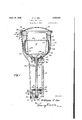
- Figure 1 is a vertical axial section of the apparatus, showing all the parts in operating position;
- Fig. 2 a section as on when the lid is opened
- Fig. 4 a perspective view of the cam sleeve.
- the apparatus includes a spherical vessel 5,'made of cast, stamped or spun metal or the like, which is secured as by a head 5 to the upper end of an upright spindle 6 mounted for limited endwise movement in a lower bearing 7 and an upper bearing 8 on a frame line lum-w, Fig. 1,
- rllhe lower end portion 10b of the receptacle 10 is tapered outward from the bottom upward as an inverted truncated cone, immediately above which is provided an annular series of'apertures 10c for discharging water the annular bracket 11 which is preferably provided with a downturned flange 11m for Stv .from the receptacle to the vessel; which series of apertures is located immediately below defiecting the water downward into the receptacle.
- the water is centrifugally extracted and is thrown outward against the inverted conical zone wall 106 in the side of the receptacle and the inclination ofthe wall carries the water upward, whence 1t 1s d1scharged through the annular serles of apertures 10e into the surrounding spherical ves-- sel, whereupon the water is thrown centrifugally outward into the channel formed by the spherical zone in the periphery of the vessel which channel has a substantial width andl depth, to form a' continuous water ⁇ balance wheel of substantial volume -as at 13; whence an excess of water may find its way outward lthrough an annular series of liquid outlet apertures 5c immediately below the sphericalzone channel and located freely-,outward a greater distance from the axis of the receptacle and the vessel than the radius of the re.- ceptacle; or ⁇ when the speed is reduced, the water will find its way downward and outward through the
- this water balance wheel will have a' substantially uniform segmental cross section throughoutits peripheral length spacedfreely from the outside of the receptacle.
- the bearing 17 is extended outward and recessed to form an annular socket 17a for receiving telescopically one end of avsleeve 19 feathered for endwise movement 'on the pintle, the inward movement of which sleeve is resisted by a coiled compression spring 20 in the socket around the pintle.
- the outer end of the sleeve 19 is provided with a disk handle or button 19a and is also recessed to form the socket 196 for receiving a nut 16a screwed on an axial bolt 166 extending from the end of the pintle, and a washer 21 is clam" d by the nut against the end of the pintle or bearing on the bottom 190 of the socket ⁇ 196, and stopping the outward move- ⁇ ment of the sleeve 19.
- a cam 19d is provided on 'tlie outer end of the sleeve 19 immediately inside of the disk handle or button, and a ange 19e is provided on the inner side of the'cam for the purpose presently to be described.
- a plunger rod 22 is mounted for endwise movement in bearings'23 and 23a formed or secured respectively on the bracket 18 and the bearing 8, upon the upper end of which rod is mounted a roller wheel 24 for riding alternately the cylindricsleeve and upon the cam protruding therefrom, when the same is in its outward and inward positions.
- the lower end of the plunger rod is supported on the outer end of a lever 25 pivoted at 26 to the lower end of the bearing 7, the lower end of the rod being seated in a cup 25a and adjustably supported by a take-up screw 27 on the end ofthe lever.
- the inner end of the lever 25 isv extended upward to form a finger 256 for centrally supporting a sleeve cup 28 in the lower end of the bearing 7; and a ball 29 is located in the cup, upon which rests the lower end of a sleeve shank 30 slidably journaled in the bearing 7, on the upper end of which sleeve is formed or secured the drive wheel 30a having aA depending flange 30a on its rim provided with a V-socket 30a by which the wheel may be continuously rotated by albelt v31 from any suitable source of power.
- a disk 32 made of friction material uponwhich may bear atwise a friction disk 33 secured to thev lower end ofthe spindle 6 as by the ange sleeve 34 and the pin '34a on the lower end portion of the spindle; and a .thin steel ,washer disk 35 may be interposed between the friction disks to ease the starting of the spindle.
- a reduced end 6a of the spindle extends ⁇ downward and is'slidably journaled in the sleeve shank 30 of the driving wheel, and byraising the driving wheel as by a depression of the plunger rod 22, the friction disk 32 and the washer disk 35 will be elevated to bear upward against and engage the friction retecal disk 33 as a clutch, so as to rotate the spindle.
- the conical disk 36 is secured to the bracket 9a around the sleeve shank 5', by which the vessel 5 is secured on the upper end of the spindle; and the bottom 5a of the vessel is'conically shaped to seat and bear upon the conical disk 36 as a brake to stop the rotation of the vessel.
- rlflie parts are so proportioned and arranged that the bottom of the vessel will normally bear upon the conical disk when the drive wheel and the friction disk thereon are in normal position freely below and disengaged from the friction disk 33 on the spindle; and that when the drive wheel is raised, its friction disk or the washer disk when used, will hear .upward against and engage the friction disk von the'spindle, and will raise the spindle to elevate the conical bottom of the vessel clear above the conical disk 36, so that the vessel may be freely rotated by the drive wheel.
- the lid 15 may be -handle or button 19a, which is pushed and.
- a centrifugal apparatus including a vessel rotatable on a vertical axis, a receiving receptacle supported within in the vessel for rotating therewith, the vessel provided with liquid outlet apertures spaced outward from the receiving receptacle a greater distance from the axis of the receptacle and the Vessel than the radius of the receptacle, and forming a. continuous spherical-zone channel ofsubstantial width and depth for receiving li uid to form a balance wheel of substantial vo ume and uniform segmental cross section throughout its peripheral length spaced freely from the outside of the receptacle.
- a centrifugal apparatus including a vessel rotatable on a vertical axis, a receiving receptacle supported ⁇ in 'the vessel for rotating therewith, and having an inverted conical-zone wall in its lower part with an annular series of liquid outlet apertures at the upperl end thereof, the vessel forming a' vcontinuous spherical-zone channel of subthroughoutv its peripheral length spaced p freely from the outside of the receptacle.
- A. centrifugal apparatus including a vessel rotatable on a vertical axis, a receiving receptacle supported within in the' vessel for rotating therewith, the vessel forming a continuous spherical-zone channelof substantial width and depth for receiving liquid to form a lbalance wheel of substantially uniform segmental cross section throughout its peripheral length spaced freely from the outside of the receptacle, and having an annular series of liquid outlet apertures at the lower side thereof spaced outward from the receiving receptacle a greater distance from the axis of the receptacle and the vessel than the radius of the receptacle, said apertures beingadapted to remain open at all times.
- a centrifugal apparatus including an upright spindle mounted for rotating with a limited endwise movement, a lstationary friction brake disk around the upper end of the spindle, a member on the upper end of the spindle normally bearing on the brake disk, a friction disk on the lower end of theA spindle, and a friction disk drive wheel normally located freely below the friction disk and mounted for raising to bear iatwise upward against the friction disk for rotating the spindle and elevating the receptacle freely above the brake disk.
- a centrifugal apparatus including an upright spindle with a vessel on its upper end, power means for rotating the spindle, clutch means for engaging and disengaging the power means ,with the'spindle, a case with a lid thereon for the vessel, a hinge between the lid and the case, normally in operative mechanism between the hinge and the clutch for actuating v the clutch, and manually actuated means on the hinge for selectively rendering the mechanism operative for actuating the clutch for engaging the power means with the spindle by a closing of the lid and automatically disengaging them by an opening of the lid, including means whereby said manually actuated means is rendered inoperative'as a Vresult of the said opening of the lid.
- a centrifugal apparatus including an upright spindle witha vessel on its upper end, a stationary case having a hinged lid for the vessel, vand means for rotating the spindle actuated by a closing of the lid -and automatically stopping the rotation by an opening of the lid, including a lid-hinge pintle, a journal bearing for the pintle having an annular socket in one end, a sleeve feathered on the .pintle for telescoping in the socket, a spring in the socket urging the sleeve out-- ward, an adjacent plunger-rod roller, and a cam on the sleeve normally outside the path of the roller adapted to be moved into the for the vessel, and means for rotating the spindle actuated by a closing of the lid and automatically stopping the rotation by an opening of the lid, including a lid-hinge pintle, a journal bearing for the pintle having an annular socket in one end, a sleeve feathered on the pint
- a centrifugal apparatus including an upright spindle mounted for rotating with a limited endwise movement, a stationaryfriction brake disk around the upper end of the spindle, a member on the upper end of the spindle normally bearing on the brake disk, a friction disk on the lower end of the spindle, and a friction disk drive wheel having a 'washer disk thereon and normally located freely below the friction disk and mounted for raising to cause the washer disk to bear latwise upward against the friction disk for rotating the spindle and elevating the receptacle freely above the brake disk.
- a centrifugal apparatus including an upright spindle with a vessel on its upper end, a stationary case having a hinged lid
Landscapes
- Engineering & Computer Science (AREA)
- Textile Engineering (AREA)
- Centrifugal Separators (AREA)
Description
April 19, 1932. w. v. 4ORF:V 1,854,621
CENTRI FUGAL DRI ER Filed May 6, 1929 '2 sheets-sheet 1 x .la 10c oo o o o o o o o a o 5b l|I l0 174/ l] I4 l 'l IHM MII: 5 'if f Il! 15 S V B@ ZZ adria 5c 5d 5d v.5.'
56 Y 9c .915 9z `ZJ@ l 54u 55 /fz 50a'\ Y rjo 5:50aw F f 6a a 50 17. J,
7/ lwuwntoz 25a 29'u 'J 2f 25 26 Z55.- lPi/illlialfz 1./ Orr l WLM/Mam April 19 1932 w.1v. @RR 1,854,621
' CENTRIFUGAL DRIER I l Filed May 6, 1929 2 Sheets-Sheet 2 Fig: 5
M'llalfz V017' athena,
Patented pr.. 19, 1932.
narran s'r-A'rss PATENT;- OFFICE WILLIAM V. ORR, OF CLEVELAND HEIGHTS, OHIO; THE CLEVELAND TRUST' COMPANY AND ADELE MARY OBR EXECUTORS 0F SAID WILLIAM V. OBR, DECEASED v CENTRIFUGAL DRIER .Application filed May 6, 1929. Serialiy No. 360,664.
The invention relates to a machine or apparatus for drying clothes by centrifugal action in a rapidly rotating receptacle, and one object of the improvement is to balance the weight of the receptacle and its contents, so that it will rotate without wabbling or undesirable vibrations.
In machines or apparatus of this type, the rotating receptacle is frequently mounted on the upper end of a vertical shaft or spindle and in order to attain the best results it is desirable., if not necessary, to rotate thereceptacle at some l1200 R. P. M.
n practice, however, it has been found that when placing Wet clothes'in the receptacle, there is usually such a difference in the weight thereof at different points more or less remote from the axis as to cause the receptacle to vibrate on its axis to such an extent as will seriously impair if not destroy the machine, especially when it is rotated at a speed of 900 R. P. M. and upwards.
This diiiculty is avoided by the present improvement, in which the clothes receptacle is mounted within a surrounding vesselshaped to form a spherical-zone annular groove or channel of substantialwidth and depth into which water extracted from the clothes is thrown by centrifugal force to form a liquid ily wheel around the outside of the receptacle and fully spaced therefrom of sufcient weight to dominate and render ineffectual and inconsequential the ordinary dider-4 ential weight of the clothes in one side or the other of the receptacle.
Another object of the improvement isito provide means which may beselectively actuated by closing the lid of the apparatus for starting a rotation of the spindle on which the clothes receptacle is mounted, and by which the -rotation will be automatically stopped by an opening of the lid; but which cannot possibly be actuated without rst opening and then closing the lid.
f This object is attained in the present improvement by mounting the vertical spindle for limitedendwise movement, with vertically movable friction driving `means and friction brake means for starting and stopV ping rotation of the spindle; and by providing a stationary case around the rotating parts, with a lid hinged at one side thereof having a normally inactive cam on the hinge pintle larranged to be selectively rendered active by manual means during the closing of the lid, to depress a plunger and operate a lever for raising the driving means and releasing the brake means by a closing of the lid, and automatically permitting a release of the driving means and an engagement of the brake means by a subsequent opening of the lid. I
The improvement is illustrated in the accompanying drawings forming part hereof, in which Figure 1 is a vertical axial section of the apparatus, showing all the parts in operating position;
Fig. 2, a section as on when the lid is opened;
F ig. 3, a section as online Fig. when the lid is closed; and
Fig. 4, a perspective view of the cam sleeve.
Similar numerals refer to similar parts throughout the drawings.
The apparatus includes a spherical vessel 5,'made of cast, stamped or spun metal or the like, which is secured as by a head 5 to the upper end of an upright spindle 6 mounted for limited endwise movement in a lower bearing 7 and an upper bearing 8 on a frame line lum-w, Fig. 1,
9 adapted to be secured, as by bolting to the -lar bracket 11 secured around its upper end portion seated upon the rim 5?; of the spherical vessel.
rllhe lower end portion 10b of the receptacle 10 is tapered outward from the bottom upward as an inverted truncated cone, immediately above which is provided an annular series of'apertures 10c for discharging water the annular bracket 11 which is preferably provided with a downturned flange 11m for Stv .from the receptacle to the vessel; which series of apertures is located immediately below defiecting the water downward into the receptacle.
' In the operation of the apparatus, a batch of wet clothes is placed in theeceptacle, and
if there is not suicient water. in the'clothes for the purpose of the present inventlon, additional water may be poured into the-receptacle; after which the spindle is rotated in thel manner presently to be described, and the rotation -of the vessel secured thereon, .rotates the receptacle by its bottom and bracket bearing contacts therewith, .until a speedofsome 1200 R. P. M. is attained. l
In this operation, the water is centrifugally extracted and is thrown outward against the inverted conical zone wall 106 in the side of the receptacle and the inclination ofthe wall carries the water upward, whence 1t 1s d1scharged through the annular serles of apertures 10e into the surrounding spherical ves-- sel, whereupon the water is thrown centrifugally outward into the channel formed by the spherical zone in the periphery of the vessel which channel has a substantial width andl depth, to form a' continuous water `balance wheel of substantial volume -as at 13; whence an excess of water may find its way outward lthrough an annular series of liquid outlet apertures 5c immediately below the sphericalzone channel and located freely-,outward a greater distance from the axis of the receptacle and the vessel than the radius of the re.- ceptacle; or`when the speed is reduced, the water will find its way downward and outward through the annular series' of apertures 5d around the bottom portion of the vessel.
It will be seen that this water balance wheel will have a' substantially uniform segmental cross section throughoutits peripheral length spacedfreely from the outside of the receptacle.
A stationary case 14, preferably made of sheet met-al, is provided around the vessel, and may be secured to an annular supporting .bracket 9a formed or mounted on top of the bracketI 9'around the upper end of the spindle 6, in which bracket is formed an annular trough 96 provided with an outlet 9c for receivingl and delivering the water discharged info the case from the rapidly rotating vesse During the rapid rotation of the vessel and the receptacle therein the water wheel maintained in the spherical zone periphery ofthe vessel exerts such a. dominating, balancing,
stabilizing or gyrating influence as to overand 17 secured as by a bracket 18 to the 'side of the case. I
The bearing 17 is extended outward and recessed to form an annular socket 17a for receiving telescopically one end of avsleeve 19 feathered for endwise movement 'on the pintle, the inward movement of which sleeve is resisted by a coiled compression spring 20 in the socket around the pintle.
The outer end of the sleeve 19 is provided with a disk handle or button 19a and is also recessed to form the socket 196 for receiving a nut 16a screwed on an axial bolt 166 extending from the end of the pintle, and a washer 21 is clam" d by the nut against the end of the pintle or bearing on the bottom 190 of the socket`196, and stopping the outward move- `ment of the sleeve 19.
A cam 19d is provided on 'tlie outer end of the sleeve 19 immediately inside of the disk handle or button, and a ange 19e is provided on the inner side of the'cam for the purpose presently to be described.
A plunger rod 22is mounted for endwise movement in bearings'23 and 23a formed or secured respectively on the bracket 18 and the bearing 8, upon the upper end of which rod is mounted a roller wheel 24 for riding alternately the cylindricsleeve and upon the cam protruding therefrom, when the same is in its outward and inward positions.
The lower end of the plunger rod is supported on the outer end of a lever 25 pivoted at 26 to the lower end of the bearing 7, the lower end of the rod being seated in a cup 25a and adjustably supported by a take-up screw 27 on the end ofthe lever. l
The inner end of the lever 25 isv extended upward to form a finger 256 for centrally supporting a sleeve cup 28 in the lower end of the bearing 7; and a ball 29 is located in the cup, upon which rests the lower end of a sleeve shank 30 slidably journaled in the bearing 7, on the upper end of which sleeve is formed or secured the drive wheel 30a having aA depending flange 30a on its rim provided with a V-socket 30a by which the wheel may be continuously rotated by albelt v31 from any suitable source of power.
Upon the upper side of the wheel 30a is located a disk 32 made of friction material, uponwhich may bear atwise a friction disk 33 secured to thev lower end ofthe spindle 6 as by the ange sleeve 34 and the pin ' 34a on the lower end portion of the spindle; and a .thin steel ,washer disk 35 may be interposed between the friction disks to ease the starting of the spindle.
A reduced end 6a of the spindle extends` downward and is'slidably journaled in the sleeve shank 30 of the driving wheel, and byraising the driving wheel as by a depression of the plunger rod 22, the friction disk 32 and the washer disk 35 will be elevated to bear upward against and engage the friction retecal disk 33 as a clutch, so as to rotate the spindle.
The conical disk 36 is secured to the bracket 9a around the sleeve shank 5', by which the vessel 5 is secured on the upper end of the spindle; and the bottom 5a of the vessel is'conically shaped to seat and bear upon the conical disk 36 as a brake to stop the rotation of the vessel.
rlflie parts are so proportioned and arranged that the bottom of the vessel will normally bear upon the conical disk when the drive wheel and the friction disk thereon are in normal position freely below and disengaged from the friction disk 33 on the spindle; and that when the drive wheel is raised, its friction disk or the washer disk when used, will hear .upward against and engage the friction disk von the'spindle, and will raise the spindle to elevate the conical bottom of the vessel clear above the conical disk 36, so that the vessel may be freely rotated by the drive wheel.
lt is evident that as the drive wheel is 'raised, the flatwise abutment of the disk with the disk 33 will permit some slippage until the conical bottom of the vessel is raised free of the conical brake disk 36, thus insur ing a gradual assumption of the load by the driving mechanism. Consequently, smoother operation without sudden shocks or strains in the machine and longer life of the wearing parts is effected.
As indicated above, when the steel washer disk is interposed between the friction disks 32 and 33, the slippage is increased to further ease the starting of the-spindle.
W hen the sleeve 19 in the lid-hinge actuating mechanism is in normal outward inoperative position, where it is held by the spring '20, as shown in Fig. 2, the lid 15 may be -handle or button 19a, which is pushed and. held inward to bring the cam 19d in the path freely opened and closed, and the roller wheel 24 will ride freely on the cylindric inner end portion of the sleeve 19; and when it is desired to operate the apparatus, thelid being held open by one hand'of theoperator, the sleeve 19 is pushed inward into inoperative position by the other hand applied to the disk of the roller wheel 24 while the lid is being closed, so that the roller willride on the cam 19d which pushes the plunger rod downward yand actuates the lever 2 5 forelevat'ing the friction disk drive wheel into flatwise' operating bearing contact with the friction on the spindle disk, and raising the bottom'of 'the vessel above the brake disk, for rotating the vessel and the receptacle therein.
When the roller wheel rides upon the cam 19d, the flange 19e on the inner end thereof engages the inner side of the wheel and prevents the Vsleeve from moving outward,y until the lid:v is again opened and the roller wheel rides upward on the cam until it is,y
tom of the vessel bearing on the brake disk,
which stops the rotation of the vessel and the receptacle and permits the withdrawal of the clothes there rom.
By the described construction and arrangement of the parts, it is impossible to operate the spinning or rotating parts without. first opening the lid and manually holding the cam in actuating position while .closing the lid; thus making it safe for an inexperienced person to operate the machineI without accidentally or unintentionally starting the spinning mechanism.
Moreover, the automatic formation and maintenance of the continuous liquid balancing wheel in the spherical-Zone channel in the vessel at a substantial interval from and around the outside of the clothes receptacle, renders it possible to spin the parts at a much greater speed than would otherwise be possible on a. spindle operating in a bearings.
` And inally,ithe use of friction driving and brake means causes agradual starting and stopping of the spinning parts, without any 'sudden straining of the bearing parts, and
permits the apparatus tobe safely operated by an inexperienced person.
l claim:
l. A centrifugal apparatus including a vessel rotatable on a vertical axis, a receiving receptacle supported within in the vessel for rotating therewith, the vessel provided with liquid outlet apertures spaced outward from the receiving receptacle a greater distance from the axis of the receptacle and the Vessel than the radius of the receptacle, and forming a. continuous spherical-zone channel ofsubstantial width and depth for receiving li uid to form a balance wheel of substantial vo ume and uniform segmental cross section throughout its peripheral length spaced freely from the outside of the receptacle.
2. A centrifugal apparatus including a vessel rotatable on a vertical axis, a receiving receptacle supported` in 'the vessel for rotating therewith, and having an inverted conical-zone wall in its lower part with an annular series of liquid outlet apertures at the upperl end thereof, the vessel forming a' vcontinuous spherical-zone channel of subthroughoutv its peripheral length spaced p freely from the outside of the receptacle.
3. A. centrifugal apparatus including a vessel rotatable on a vertical axis, a receiving receptacle supported within in the' vessel for rotating therewith, the vessel forming a continuous spherical-zone channelof substantial width and depth for receiving liquid to form a lbalance wheel of substantially uniform segmental cross section throughout its peripheral length spaced freely from the outside of the receptacle, and having an annular series of liquid outlet apertures at the lower side thereof spaced outward from the receiving receptacle a greater distance from the axis of the receptacle and the vessel than the radius of the receptacle, said apertures beingadapted to remain open at all times.
4. A centrifugal apparatus including an upright spindle mounted for rotating with a limited endwise movement, a lstationary friction brake disk around the upper end of the spindle, a member on the upper end of the spindle normally bearing on the brake disk, a friction disk on the lower end of theA spindle, and a friction disk drive wheel normally located freely below the friction disk and mounted for raising to bear iatwise upward against the friction disk for rotating the spindle and elevating the receptacle freely above the brake disk.. v
5. A centrifugal apparatus including an upright spindle with a vessel on its upper end, power means for rotating the spindle, clutch means for engaging and disengaging the power means ,with the'spindle, a case with a lid thereon for the vessel, a hinge between the lid and the case, normally in operative mechanism between the hinge and the clutch for actuating v the clutch, and manually actuated means on the hinge for selectively rendering the mechanism operative for actuating the clutch for engaging the power means with the spindle by a closing of the lid and automatically disengaging them by an opening of the lid, including means whereby said manually actuated means is rendered inoperative'as a Vresult of the said opening of the lid. f
6. A centrifugal apparatus including an upright spindle witha vessel on its upper end, a stationary case having a hinged lid for the vessel, vand means for rotating the spindle actuated by a closing of the lid -and automatically stopping the rotation by an opening of the lid, including a lid-hinge pintle, a journal bearing for the pintle having an annular socket in one end, a sleeve feathered on the .pintle for telescoping in the socket, a spring in the socket urging the sleeve out-- ward, an adjacent plunger-rod roller, and a cam on the sleeve normally outside the path of the roller adapted to be moved into the for the vessel, and means for rotating the spindle actuated by a closing of the lid and automatically stopping the rotation by an opening of the lid, including a lid-hinge pintle, a journal bearing for the pintle having an annular socket in one end, a sleeve feathered on the pintle for telescoping in the socket, va spring in the socket urging the sleeve outward, an adjacent plunger-rod roller, and a cam on the sleeve normally outside the path of the roller adapted to be moved into the path of the roller by pressing the sleeve inward against the action of the spring, there being a iange in the inner side of the cam engaging the inner side of the roller when riding on the cam. l
8'. A centrifugal apparatus including an upright spindle mounted for rotating with a limited endwise movement, a stationaryfriction brake disk around the upper end of the spindle, a member on the upper end of the spindle normally bearing on the brake disk, a friction disk on the lower end of the spindle, and a friction disk drive wheel having a 'washer disk thereon and normally located freely below the friction disk and mounted for raising to cause the washer disk to bear latwise upward against the friction disk for rotating the spindle and elevating the receptacle freely above the brake disk.
In testimony that l claim the above, l have hereunto subscribed my name.
WILLIAM V. ORB.
path of the roller by pressing the sleeve inward against the action of the spring.
7. A centrifugal apparatus including an upright spindle with a vessel on its upper end, a stationary case having a hinged lid
Priority Applications (1)
| Application Number | Priority Date | Filing Date | Title |
|---|---|---|---|
| US360664A US1854621A (en) | 1929-05-06 | 1929-05-06 | Centrifugal drier |
Applications Claiming Priority (1)
| Application Number | Priority Date | Filing Date | Title |
|---|---|---|---|
| US360664A US1854621A (en) | 1929-05-06 | 1929-05-06 | Centrifugal drier |
Publications (1)
| Publication Number | Publication Date |
|---|---|
| US1854621A true US1854621A (en) | 1932-04-19 |
Family
ID=23418943
Family Applications (1)
| Application Number | Title | Priority Date | Filing Date |
|---|---|---|---|
| US360664A Expired - Lifetime US1854621A (en) | 1929-05-06 | 1929-05-06 | Centrifugal drier |
Country Status (1)
| Country | Link |
|---|---|
| US (1) | US1854621A (en) |
Cited By (5)
| Publication number | Priority date | Publication date | Assignee | Title |
|---|---|---|---|---|
| US2549756A (en) * | 1945-02-23 | 1951-04-24 | Gen Motors Corp | Domestic appliance |
| US2603982A (en) * | 1947-01-28 | 1952-07-22 | Apex Electrical Mfg Co | Washing machine with water balancer |
| US2700473A (en) * | 1946-11-09 | 1955-01-25 | Automatic Washer Company | Counterbalanced extractor |
| DE1146811B (en) * | 1958-09-04 | 1963-04-04 | Scharpf Komm Ges Geb | Laundry centrifuge with double-walled, internally perforated centrifugal drum rotating around a vertical axis |
| US3190447A (en) * | 1961-03-23 | 1965-06-22 | Whirlpool Co | Rotatable receptacle balancing apparatus with roller bearing deflector mounting |
-
1929
- 1929-05-06 US US360664A patent/US1854621A/en not_active Expired - Lifetime
Cited By (5)
| Publication number | Priority date | Publication date | Assignee | Title |
|---|---|---|---|---|
| US2549756A (en) * | 1945-02-23 | 1951-04-24 | Gen Motors Corp | Domestic appliance |
| US2700473A (en) * | 1946-11-09 | 1955-01-25 | Automatic Washer Company | Counterbalanced extractor |
| US2603982A (en) * | 1947-01-28 | 1952-07-22 | Apex Electrical Mfg Co | Washing machine with water balancer |
| DE1146811B (en) * | 1958-09-04 | 1963-04-04 | Scharpf Komm Ges Geb | Laundry centrifuge with double-walled, internally perforated centrifugal drum rotating around a vertical axis |
| US3190447A (en) * | 1961-03-23 | 1965-06-22 | Whirlpool Co | Rotatable receptacle balancing apparatus with roller bearing deflector mounting |
Similar Documents
| Publication | Publication Date | Title |
|---|---|---|
| US2269190A (en) | Washing machine | |
| US2470140A (en) | Washing machine having rotatable tub with upper and lower discharge means | |
| US1757585A (en) | Centrifugal drier | |
| US1854621A (en) | Centrifugal drier | |
| US2797569A (en) | Clothes washing machine | |
| US2033146A (en) | Washing machine | |
| US2574617A (en) | Washing machine | |
| US1940812A (en) | Means for discharging material from centrifugal baskets | |
| US2275846A (en) | Washing machine | |
| US2343694A (en) | Blood-separating machine for serum production | |
| US1753722A (en) | Support for centrifugals | |
| US2138858A (en) | Cleaning and extracting machine | |
| US1564503A (en) | Centrifugal machine for treating textiles with liquid and gases | |
| US2095505A (en) | Laundry machine | |
| US2167397A (en) | Water-cooled wire block | |
| US1968692A (en) | Centrifugal machine | |
| US3304752A (en) | Device for centrifuging yarn laps | |
| US1253987A (en) | Centrifugal extractor. | |
| US2186704A (en) | Centrifugal extractor | |
| US2169260A (en) | Safety device | |
| US1202890A (en) | Centrifugal machine. | |
| US1768851A (en) | Centrifugal extractor and mechanism for balancing and operating rotative containers for the same or similar devices | |
| US1905306A (en) | Centrifugal apparatus | |
| US2067572A (en) | Laundry machine | |
| US2219177A (en) | Centrifugal extractor |