US1854618A - Roll polishing machine - Google Patents
Roll polishing machine Download PDFInfo
- Publication number
- US1854618A US1854618A US443981A US44398130A US1854618A US 1854618 A US1854618 A US 1854618A US 443981 A US443981 A US 443981A US 44398130 A US44398130 A US 44398130A US 1854618 A US1854618 A US 1854618A
- Authority
- US
- United States
- Prior art keywords
- spindle
- roll
- machine
- bearing
- polishing machine
- Prior art date
- Legal status (The legal status is an assumption and is not a legal conclusion. Google has not performed a legal analysis and makes no representation as to the accuracy of the status listed.)
- Expired - Lifetime
Links
- 238000005498 polishing Methods 0.000 title description 7
- XLYOFNOQVPJJNP-UHFFFAOYSA-N water Substances O XLYOFNOQVPJJNP-UHFFFAOYSA-N 0.000 description 8
- 238000005530 etching Methods 0.000 description 3
- RYGMFSIKBFXOCR-UHFFFAOYSA-N Copper Chemical compound [Cu] RYGMFSIKBFXOCR-UHFFFAOYSA-N 0.000 description 2
- 229910052802 copper Inorganic materials 0.000 description 2
- 239000010949 copper Substances 0.000 description 2
- 239000004575 stone Substances 0.000 description 2
- 229940000425 combination drug Drugs 0.000 description 1
- 238000000034 method Methods 0.000 description 1
- 238000012986 modification Methods 0.000 description 1
- 230000004048 modification Effects 0.000 description 1
- 230000001603 reducing effect Effects 0.000 description 1
Images

Classifications
-
- B—PERFORMING OPERATIONS; TRANSPORTING
- B24—GRINDING; POLISHING
- B24B—MACHINES, DEVICES, OR PROCESSES FOR GRINDING OR POLISHING; DRESSING OR CONDITIONING OF ABRADING SURFACES; FEEDING OF GRINDING, POLISHING, OR LAPPING AGENTS
- B24B5/00—Machines or devices designed for grinding surfaces of revolution on work, including those which also grind adjacent plane surfaces; Accessories therefor
- B24B5/02—Machines or devices designed for grinding surfaces of revolution on work, including those which also grind adjacent plane surfaces; Accessories therefor involving centres or chucks for holding work
- B24B5/04—Machines or devices designed for grinding surfaces of revolution on work, including those which also grind adjacent plane surfaces; Accessories therefor involving centres or chucks for holding work for grinding cylindrical surfaces externally
Definitions
- This invention relates to a machine for taking down the surface of etched copper rolls used in printing. These rolls are etched usually by use of a pantograph which produces a shallow etching and the etching is taken off by a slight reduction in the diameter of the roll by grinding methods or the equivalent.
- This invention has for its objects the provision of means for supporting such a roll on a spindle so that the roll can be rotated and the reducing action carried out on the roll in a simple and convenient manner; to provide means whereby the spindle can be turned out away from one bearing so that the roll can be removed without removing the spindle; to provide a water box underneath the roll for the usual purpose but arranged so that it can be moved up and down away from the roll to allow it to be placed in operative position and removed therefrom without disturbing the roll; to provide rest for the spindle when it is moved out of its operative position soas to hold the spindle in horizontal position with the free end out away from its bearing for convenience in removing the roll from the spindle and replacing it by another and to provide an improved form of bearing for the free end of the spindle which will allow the spindle to be introduced and removed very readily.
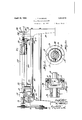
- FIG. 1 is a side elevation of a machine constructed in accordance with this invention, parts being shown in section;
- Fig. 2 is a sectional view of the joint by which the spindle is connected with the driving shaft;
- Fig. 3 is an end view of the same with one I of the centers in section;
- Fig. 4 is a plan of the machine showing two positions of the spindle in full and dotted lines; r Fig. 5 is an end view;
- Fig. 6 is a perspective view of the right hand end of this machine.
- Fig. 7 is a sectional view on the line 77 of Fig. 4, and
- Fig. 8 is a transverse sectional view on the line 88 of Fig. 1. I 1
- the copper or other metalrolls used in printing are engraved by the use of a pantograph or other mechanical device and etched so that they have the figure to be printed in intaglio thereon.
- this surface has to be taken off down to the bottom of the etching and the roll is again etched and used over again.
- the grinding down of this surface for these purposes was practically a hand operation. 'At least the manipulation of the rolls and the parts were all done by hand.
- This machine is designed, not to provide automatic means for accomplish ing the desired results, but to provide a convenient device in which the roll can be rotated so that an operator can reduce the sur: 7
- the machine is mounted on a frame 10 and the power is received through a pulley 11,or in any other desired way, and transmitted by a belt 12 to the driving shaft 13 supported in bearings at one end of the machine.
- This shaft is provided with a head 1% keyed thereto.
- This head is circular and hollow and is provided with adj ustable center points 15 projecting in radially from opposite sides and on the same axis. In this case two of them are shown for supportinga hollow ball joint 16.
- this member 16 can be turned on the'axis of these two opposite pins 15.
- This head itself is provided with two more opposite pins 17, at right angles tothe axis of the pins 15 and they project intoa spherical head 18 on a spindle 19. This provides freedom forturning the spindle on two axes at right angles to each other.
- the spindle extends across the machine and is provided with cone supports 20 at its opposite ends. One of these is removable and is secured in position by a nut 21 screwing on the spindle. These two cones support the roll or cylinder 22 which is to be operated upon.
- This spindle is supported at one end, of course, by the head 14 and at the other it has its bearing 24 in the opposite end of the machine. This bearing is open in front, practically horizontally, so that it furnishes only a semi-circular bearing at the rear.
- a pivoted member 25 having a handle 26 and also having a semi-cylindrical bearing open at one side through an opening 27. WVhen the handle 26 is turned down these two openings are in registration and the end of the spindle can be inserted. Then the handle can be turned back up as shown in Fig. 1 and the spindle is held in place.
- an integral projection 28 having a run-way 30 at the top on which the spindle can be supported when it is pulled out in the position shown in Figs. 4; and 5.
- This projection or bracket 29 has an upwardly projecting end 31.
- a stationary arcuate bracket or support 32 for supporting that end of the spindle.
- This worm meshes with the wheel 38 on a shaft 39.
- This shaft 39 is supported by brackets 4:0 fixedly carried on a rod 41 which is fixed on the machine and constitutes a part of the frame.
- a stationary rod 412 carries astationary bracket 43 and a shaft 44.
- the shafts 39 and 442 carry arms 45. These arms are pivotally connected to the bottom of a trough 46.
- the centers of the shafts 39 and 44 are shown as the same distance apart as the centers of the studs which connect the arms 45 with the bottom of the trough.
- the handle 26 is turned up and the free end of the spindle is moved out on the bracket 29 where it is supported in the same plane in which it has previously been supported. It is then lifted by its end and brought up over its projection, as shown in dotted lines. Then it is supported at the other end by the universal joint and by the bracket 32. Now the nut 21 can be removed and also the cone 20 which leaves it free to remove the roll 22 and replace it by another. The cone and nut are returned and the spindle moved back to the position shown in Fig. 4E and finally to the position shown in Fig. 1 and the lock 25 is turned upwardly. The spindle now can be rotated just the same as if it were permanently fixed in its concentric bearings and the surface removed by a grinding wheel if desired or by a hand stone, while the roll is being rotated.
- a roll polishing machine In a roll polishing machine, the combination with a driving shaft and a universal joint carried thereby, of a spindle connected with said joint, means on said spindle for holding the opposite ends of a roll to be polished, the means at the free end of the spindle being detachable to allow for replacing the roll, a bearing on the machine for the free end of the said spindle, a bracket extending from the machine at the free end of the spindle and having a horizontal run-way thereon for said spindle, whereby the spindle can be released from its bearing and swung out to the side about said joint as an axis and a support at the head end of the machine for the opposite end of the spindle when the free end is moved outwardly beyond said bracket for convenience in replacing a roll on the spindle.
- a roll polishing machine the combination with a driving shaft having a pivot joint at the end thereof, of a spindle connected with the pivot joint and capable of swinging thereon, a bearing at the opposite end of the spindle having an open side, means on the spindle for holding a roll to be polished, the machine, at the free end of the spindle, having a bracket provided with'a top run-way in line with the bottom of said open bearing, whereby the spindle can be swung on its pivot to rest on the said run-way and a support at the driving shaft end of the machine for supporting the spindle at that point when it is removed from said run-way.
- a spindle for holding the roll to be polished, said spindle being movable to a position in which the roll can be replaced, of a water tank located under the roll, a hand wheel, a shaft parallel with the spindle, a worm and worm wheel connection between the hand wheel and shaft for turning the shaft, a parallel shaft, arms on said shafts extending in parallel directions, and a water tank, said arms being connected with the water tank at points the same distance apart as said shafts, whereby the turning of the hand wheel will swing the water tank downwardly and rearwardly out of the way.
- a roll polishing machine In a roll polishing machine, the combination with a driving shaft having a pivot joint at the end thereof, of a spindle connected with the pivot joint and capable of swinging thereon, a bearing at the opposite end of the spindle, means on the spindle for holding a roll to be polished, and a bracket provided with a top runway at the side of said bearing, whereby the spindle can be swung on its pivot to rest on the said runway.
- the combi nation with a driving shaft having a pivot joint at the end thereof, of a spindle connected with the pivot joint and capable of swinging thereon, a bearing at the opposite end of the spindle, means on the spindle for holding a roll to be polished, a bracket provided with a top run-way at the side of said bearing, whereby the spindle can be swung on its pivot to rest on the said run-way, and a support at the driving shaft end of the machine for supporting the spindle at that point when it is removed from said run-way.
Landscapes
- Engineering & Computer Science (AREA)
- Mechanical Engineering (AREA)
- Finish Polishing, Edge Sharpening, And Grinding By Specific Grinding Devices (AREA)
Description
April 19, 1932. J. P. CGRADY 1,854,618
ROLL POLI SHING MACHINE Filed April 14, 1930 2 Sheets-Sheet l April 19, 1932. j MCGIIQADY 1,854,618
- ROLL POLISHING MACHINE Filed April 14. 1950 Z-SheetS-Sheet 2 & 2-07 m Patented Apr. 19, 1932 UNITED STATES JAMES P, MCGRADY, OF WORCESTER, MASSACHUSETTS Rom. rotrsmue MACHINE Application filed April 14, 1930. Serial No. 443,981.
This invention relates to a machine for taking down the surface of etched copper rolls used in printing. These rolls are etched usually by use of a pantograph which produces a shallow etching and the etching is taken off by a slight reduction in the diameter of the roll by grinding methods or the equivalent.
This invention has for its objects the provision of means for supporting such a roll on a spindle so that the roll can be rotated and the reducing action carried out on the roll in a simple and convenient manner; to provide means whereby the spindle can be turned out away from one bearing so that the roll can be removed without removing the spindle; to provide a water box underneath the roll for the usual purpose but arranged so that it can be moved up and down away from the roll to allow it to be placed in operative position and removed therefrom without disturbing the roll; to provide rest for the spindle when it is moved out of its operative position soas to hold the spindle in horizontal position with the free end out away from its bearing for convenience in removing the roll from the spindle and replacing it by another and to provide an improved form of bearing for the free end of the spindle which will allow the spindle to be introduced and removed very readily.
Other objects and advantages of the invention will appear hereinafter.
Reference is to be had to the accompanying drawings in which Fig. 1 is a side elevation of a machine constructed in accordance with this invention, parts being shown in section;
Fig. 2 is a sectional view of the joint by which the spindle is connected with the driving shaft;
Fig. 3 is an end view of the same with one I of the centers in section;
Fig. 4 is a plan of the machine showing two positions of the spindle in full and dotted lines; r Fig. 5 is an end view;
Fig. 6 is a perspective view of the right hand end of this machine;
Fig. 7 is a sectional view on the line 77 of Fig. 4, and
Fig. 8 is a transverse sectional view on the line 88 of Fig. 1. I 1
The copper or other metalrolls used in printing are engraved by the use of a pantograph or other mechanical device and etched so that they have the figure to be printed in intaglio thereon. When the pattern or print to be produced is discontinued, or when the roll is damaged or worn out, this surface has to be taken off down to the bottom of the etching and the roll is again etched and used over again. Heretofore the grinding down of this surface for these purposes was practically a hand operation. 'At least the manipulation of the rolls and the parts were all done by hand. This machine is designed, not to provide automatic means for accomplish ing the desired results, but to provide a convenient device in which the roll can be rotated so that an operator can reduce the sur: 7
face by a grinding stone, in which the roll can be removed and replaced without any great inconvenience to the operator'and time can be saved and in which the other objects above mentioned are accomplished.
In the drawings the machine is mounted on a frame 10 and the power is received through a pulley 11,or in any other desired way, and transmitted by a belt 12 to the driving shaft 13 supported in bearings at one end of the machine. This shaft is provided with a head 1% keyed thereto. This head is circular and hollow and is provided with adj ustable center points 15 projecting in radially from opposite sides and on the same axis. In this case two of them are shown for supportinga hollow ball joint 16. Obviously this member 16 can be turned on the'axis of these two opposite pins 15. This head itself is provided with two more opposite pins 17, at right angles tothe axis of the pins 15 and they project intoa spherical head 18 on a spindle 19. This provides freedom forturning the spindle on two axes at right angles to each other.
The spindle extends across the machine and is provided with cone supports 20 at its opposite ends. One of these is removable and is secured in position by a nut 21 screwing on the spindle. These two cones support the roll or cylinder 22 which is to be operated upon. This spindle is supported at one end, of course, by the head 14 and at the other it has its bearing 24 in the opposite end of the machine. This bearing is open in front, practically horizontally, so that it furnishes only a semi-circular bearing at the rear.
To hold the spindle in place a pivoted member 25 is employed having a handle 26 and also having a semi-cylindrical bearing open at one side through an opening 27. WVhen the handle 26 is turned down these two openings are in registration and the end of the spindle can be inserted. Then the handle can be turned back up as shown in Fig. 1 and the spindle is held in place.
At the end of the frame on which the bearing 24: is located is an integral projection 28 having a run-way 30 at the top on which the spindle can be supported when it is pulled out in the position shown in Figs. 4; and 5. This projection or bracket 29 has an upwardly projecting end 31. At the other end of the machine is a stationary arcuate bracket or support 32 for supporting that end of the spindle.
At the head end of the machine there is a hand wheel 35 on a shaft 36 having a worm 37 thereon. This worm meshes with the wheel 38 on a shaft 39. This shaft 39 is supported by brackets 4:0 fixedly carried on a rod 41 which is fixed on the machine and constitutes a part of the frame. There is a similar arrangement at the back of the machine where a stationary rod 412 carries astationary bracket 43 and a shaft 44. The shafts 39 and 442 carry arms 45. These arms are pivotally connected to the bottom of a trough 46. The centers of the shafts 39 and 44 are shown as the same distance apart as the centers of the studs which connect the arms 45 with the bottom of the trough. Therefore this is a parallel motion and the swinging of the shaft 39 by the hand wheel will cause the trough to move from the limiting position shown in Fig. 8 to the limiting position shown in dotted lines. Therefore this trough can be moved up and down as indicated in that figure. lVhen it moves down it moves backwardly out of the way. It is intended to receive water and the roll dips down into it as shown. The purpose is to Wet the roll during the operation of grinding down its surface. The trough has an extending plate 47 at the rear passing upwardly at an incline so that any water spattering over will be returned to the trough and will not drop down on the machinery.
In the use of the device the handle 26 is turned up and the free end of the spindle is moved out on the bracket 29 where it is supported in the same plane in which it has previously been supported. It is then lifted by its end and brought up over its projection, as shown in dotted lines. Then it is supported at the other end by the universal joint and by the bracket 32. Now the nut 21 can be removed and also the cone 20 which leaves it free to remove the roll 22 and replace it by another. The cone and nut are returned and the spindle moved back to the position shown in Fig. 4E and finally to the position shown in Fig. 1 and the lock 25 is turned upwardly. The spindle now can be rotated just the same as if it were permanently fixed in its concentric bearings and the surface removed by a grinding wheel if desired or by a hand stone, while the roll is being rotated.
This constitutes a very simple means in which this heavy roll can be supported both in its bearings and in position for the roll to be changed and a very simple means for securing it in its running position. Also the water tank can be manipulated very easily to bring it down out of the way so that the roll can be removed in the manner specified.
Although I have illustrated and described only one form of the invention I am aware of the fact that modifications can be made therein by any person skilled in the art without departing from the scope of the invention as expressed in the claims. Therefore I do not wish to be limited in this respect but what I do claim is 1. In a roll polishing machine, the combination with a driving shaft and a universal joint carried thereby, of a spindle connected with said joint, means on said spindle for holding the opposite ends of a roll to be polished, the means at the free end of the spindle being detachable to allow for replacing the roll, a bearing on the machine for the free end of the said spindle, a bracket extending from the machine at the free end of the spindle and having a horizontal run-way thereon for said spindle, whereby the spindle can be released from its bearing and swung out to the side about said joint as an axis and a support at the head end of the machine for the opposite end of the spindle when the free end is moved outwardly beyond said bracket for convenience in replacing a roll on the spindle.
2. In a roll polishing machine, the combination with a driving shaft having a pivot joint at the end thereof, of a spindle connected with the pivot joint and capable of swinging thereon, a bearing at the opposite end of the spindle having an open side, means on the spindle for holding a roll to be polished, the machine, at the free end of the spindle, having a bracket provided with'a top run-way in line with the bottom of said open bearing, whereby the spindle can be swung on its pivot to rest on the said run-way and a support at the driving shaft end of the machine for supporting the spindle at that point when it is removed from said run-way.
8. In a roll polishing machine, the combination with a spindle for holding the roll to be polished, said spindle being movable to a position in which the roll can be replaced, of a water tank located under the roll, a hand wheel, a shaft parallel with the spindle, a worm and worm wheel connection between the hand wheel and shaft for turning the shaft, a parallel shaft, arms on said shafts extending in parallel directions, and a water tank, said arms being connected with the water tank at points the same distance apart as said shafts, whereby the turning of the hand wheel will swing the water tank downwardly and rearwardly out of the way.
4:. In a roll polishing machine, the combination with a driving shaft having a pivot joint at the end thereof, of a spindle connected with the pivot joint and capable of swinging thereon, a bearing at the opposite end of the spindle, means on the spindle for holding a roll to be polished, and a bracket provided with a top runway at the side of said bearing, whereby the spindle can be swung on its pivot to rest on the said runway.
5. In a roll polishing machine, the combi nation with a driving shaft having a pivot joint at the end thereof, of a spindle connected with the pivot joint and capable of swinging thereon, a bearing at the opposite end of the spindle, means on the spindle for holding a roll to be polished, a bracket provided with a top run-way at the side of said bearing, whereby the spindle can be swung on its pivot to rest on the said run-way, and a support at the driving shaft end of the machine for supporting the spindle at that point when it is removed from said run-way.
In testimony whereof I have hereunto affixed my signature.
JAMES P. MoGRADY.
Priority Applications (1)
| Application Number | Priority Date | Filing Date | Title |
|---|---|---|---|
| US443981A US1854618A (en) | 1930-04-14 | 1930-04-14 | Roll polishing machine |
Applications Claiming Priority (1)
| Application Number | Priority Date | Filing Date | Title |
|---|---|---|---|
| US443981A US1854618A (en) | 1930-04-14 | 1930-04-14 | Roll polishing machine |
Publications (1)
| Publication Number | Publication Date |
|---|---|
| US1854618A true US1854618A (en) | 1932-04-19 |
Family
ID=23762982
Family Applications (1)
| Application Number | Title | Priority Date | Filing Date |
|---|---|---|---|
| US443981A Expired - Lifetime US1854618A (en) | 1930-04-14 | 1930-04-14 | Roll polishing machine |
Country Status (1)
| Country | Link |
|---|---|
| US (1) | US1854618A (en) |
Cited By (7)
| Publication number | Priority date | Publication date | Assignee | Title |
|---|---|---|---|---|
| US2417409A (en) * | 1941-11-03 | 1947-03-18 | Garrison Machine Works Inc | Gear chuck |
| US2423244A (en) * | 1944-01-28 | 1947-07-01 | Jones & Lamson Mach Co | Power-operated chuck |
| US3031808A (en) * | 1959-02-06 | 1962-05-01 | Attilio R Spicacci | Apparatus for manufacturing bearing races and the like |
| US3125837A (en) * | 1964-03-24 | Self aligning ambox | ||
| US3145507A (en) * | 1961-03-01 | 1964-08-25 | Landis Tool Co | Axial locating means for workpieces |
| US3665657A (en) * | 1970-07-22 | 1972-05-30 | Fmc Corp | Apparatus for mounting disc brake rotors during truing |
| US5830044A (en) * | 1994-04-28 | 1998-11-03 | Sms Schloemann-Siemag Aktiengesellschaft | Roll grinding machine |
-
1930
- 1930-04-14 US US443981A patent/US1854618A/en not_active Expired - Lifetime
Cited By (7)
| Publication number | Priority date | Publication date | Assignee | Title |
|---|---|---|---|---|
| US3125837A (en) * | 1964-03-24 | Self aligning ambox | ||
| US2417409A (en) * | 1941-11-03 | 1947-03-18 | Garrison Machine Works Inc | Gear chuck |
| US2423244A (en) * | 1944-01-28 | 1947-07-01 | Jones & Lamson Mach Co | Power-operated chuck |
| US3031808A (en) * | 1959-02-06 | 1962-05-01 | Attilio R Spicacci | Apparatus for manufacturing bearing races and the like |
| US3145507A (en) * | 1961-03-01 | 1964-08-25 | Landis Tool Co | Axial locating means for workpieces |
| US3665657A (en) * | 1970-07-22 | 1972-05-30 | Fmc Corp | Apparatus for mounting disc brake rotors during truing |
| US5830044A (en) * | 1994-04-28 | 1998-11-03 | Sms Schloemann-Siemag Aktiengesellschaft | Roll grinding machine |
Similar Documents
| Publication | Publication Date | Title |
|---|---|---|
| US1854618A (en) | Roll polishing machine | |
| US2088402A (en) | Resurfacing machine for paper making machine suction boxes | |
| US1958203A (en) | Routing machine | |
| US1262780A (en) | Machine for shaping the heads of barrels or the like. | |
| US1927847A (en) | Mill table | |
| US1714246A (en) | Grinding machine | |
| US1969805A (en) | Floor surfacer and polisher | |
| US2865142A (en) | Apparatus for surfacing glass sheets | |
| US2544318A (en) | Method and means for centerless grinding without propping of work by abrading surface | |
| US1393046A (en) | Wrist-pin grinder | |
| US1701815A (en) | Spindle sanding machine | |
| US2241568A (en) | Machine for abrading photoengraving cylinders | |
| US962274A (en) | Gem grinder and polisher. | |
| US1310071A (en) | Machine for shaping and polishing articles of celluloid and the like | |
| US1967964A (en) | Grinding machine | |
| US1733098A (en) | Centerless grinding machine | |
| US1086368A (en) | Surfacing and polishing machine. | |
| US1864376A (en) | Disk grinder and polisher | |
| US2127851A (en) | Floor surfacing machine | |
| US1449266A (en) | Machine for grinding the edges of lenses | |
| US1468432A (en) | Floor-surfacing machine | |
| US3815291A (en) | Sanding machine for bowling alleys | |
| US1691898A (en) | Machine for shaping and grinding stones for blast furnaces | |
| US992730A (en) | Surfacing-machine. | |
| US1915853A (en) | Grinding machine for crank shafts |