US1854586A - Universal joint - Google Patents
Universal joint Download PDFInfo
- Publication number
- US1854586A US1854586A US287681A US28768128A US1854586A US 1854586 A US1854586 A US 1854586A US 287681 A US287681 A US 287681A US 28768128 A US28768128 A US 28768128A US 1854586 A US1854586 A US 1854586A
- Authority
- US
- United States
- Prior art keywords
- arms
- sleeves
- yoke
- universal joint
- gears
- Prior art date
- Legal status (The legal status is an assumption and is not a legal conclusion. Google has not performed a legal analysis and makes no representation as to the accuracy of the status listed.)
- Expired - Lifetime
Links
- 238000010276 construction Methods 0.000 description 1
- 239000011435 rock Substances 0.000 description 1
Images
Classifications
-
- F—MECHANICAL ENGINEERING; LIGHTING; HEATING; WEAPONS; BLASTING
- F16—ENGINEERING ELEMENTS AND UNITS; GENERAL MEASURES FOR PRODUCING AND MAINTAINING EFFECTIVE FUNCTIONING OF MACHINES OR INSTALLATIONS; THERMAL INSULATION IN GENERAL
- F16D—COUPLINGS FOR TRANSMITTING ROTATION; CLUTCHES; BRAKES
- F16D3/00—Yielding couplings, i.e. with means permitting movement between the connected parts during the drive
- F16D3/16—Universal joints in which flexibility is produced by means of pivots or sliding or rolling connecting parts
- F16D3/18—Universal joints in which flexibility is produced by means of pivots or sliding or rolling connecting parts the coupling parts (1) having slidably-interengaging teeth
-
- F—MECHANICAL ENGINEERING; LIGHTING; HEATING; WEAPONS; BLASTING
- F16—ENGINEERING ELEMENTS AND UNITS; GENERAL MEASURES FOR PRODUCING AND MAINTAINING EFFECTIVE FUNCTIONING OF MACHINES OR INSTALLATIONS; THERMAL INSULATION IN GENERAL
- F16H—GEARING
- F16H1/00—Toothed gearings for conveying rotary motion
- F16H1/006—Toothed gearings for conveying rotary motion the driving and driven axes being designed to assume variable positions relative to one another during operation
-
- Y—GENERAL TAGGING OF NEW TECHNOLOGICAL DEVELOPMENTS; GENERAL TAGGING OF CROSS-SECTIONAL TECHNOLOGIES SPANNING OVER SEVERAL SECTIONS OF THE IPC; TECHNICAL SUBJECTS COVERED BY FORMER USPC CROSS-REFERENCE ART COLLECTIONS [XRACs] AND DIGESTS
- Y10—TECHNICAL SUBJECTS COVERED BY FORMER USPC
- Y10T—TECHNICAL SUBJECTS COVERED BY FORMER US CLASSIFICATION
- Y10T74/00—Machine element or mechanism
- Y10T74/19—Gearing
- Y10T74/19502—Pivotally supported
- Y10T74/19521—Bevel
Definitions
- Another object of the invention is to provide segmental racks having their teeth staggered in order to prevent lateral movement of the segments when the teeth thereof are in mesh.
- Another object of the invention is to provide a device of this character having a hand grip associated therewith in order that the joint can be braced when in operation.
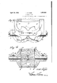
- Figure 2 is an end View.
- Figure 3 is a plan view.
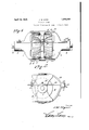
- Figure 1 is a longitudinal sectional view.
- the device comprises a pair of heads 1 which have formed integral therewith sleeves 2, in which are rotatable the opposed ends of the shafts 3, either one of which may be the driving shaft.
- the heads 1 are provided with laterally spaced segmental racks 4;, the teeth 5 of each rack being staggered so that when in mesh lateral movement of the racks is prevented, as will be obvious. 7
- the sleeves 2 are provided with transverse slots 13 in which are engaged the arms of-the yoke 14, there being set screws 15 carried by the sleeves for engaging the yoke arms to hold the same interlocked with the sleeves when desired.
- the terminals of the yoke arms 14 are riveted to the ends of the strap 16, said strap being also riveted between the flanges 11 and 12 of the arms 10, said strap having engaged thereon a hand grip 17.
- the bight portion of the yoke is riveted between the flanges 11 and 12 of the arms 9.
- a device of the character described comprising a pair of heads having sleeves carried thereby, said sleeves having transverse slots therein, segmental racks carried by the heads and in mesh with each other, shafts journaled in the sleeves and having gears carried by their inner ends, said gears being in mesh between the racks, plates pivotally Connecting the racks, said plates having arms, a yoke fixed to certain of the arms and slidable in the slots, means for securing the yoke within the slots, and a hand grip associated with certain other of the arms.
Landscapes
- Engineering & Computer Science (AREA)
- General Engineering & Computer Science (AREA)
- Mechanical Engineering (AREA)
- Prostheses (AREA)
Description
April 19, 1932. w, Y R 1,854,586
UNIVERSAL JOINT Original Fild June 25, 1928 '2 Sheets-Sheet 1 April 19, 1932. I J. w. HYER 1,854,586
UNIVERSAL JOINT Original Filed June 23, 1928 2 Sheets-Sheet 2 a nuem oz .9 7 6 JW g-er flame/1 Patented Apr. 19, 1932 STAT S TENT error;
JOHN W. HYEB, OF KIRKWOOID, MISSOURI UNIVERSAL JOINT Application filed June 23, 1926, Serial Another object of the invention is to provide segmental racks having their teeth staggered in order to prevent lateral movement of the segments when the teeth thereof are in mesh.
' Another object of the invention is to provide a device of this character having a hand grip associated therewith in order that the joint can be braced when in operation.
lVith these and other objects in view, th1s invention resides in the novel features of construction, formation, combination and arrangement of parts to be hereinafter more fully described, claimed and illustrated in the accompanying drawings, in which Figure 1 is a side elevation.
Figure 2 is an end View.
Figure 3 is a plan view.
Figure 1 is a longitudinal sectional view.
The device comprises a pair of heads 1 which have formed integral therewith sleeves 2, in which are rotatable the opposed ends of the shafts 3, either one of which may be the driving shaft.
The heads 1 are provided with laterally spaced segmental racks 4;, the teeth 5 of each rack being staggered so that when in mesh lateral movement of the racks is prevented, as will be obvious. 7
Fixed to the inner ends of the shafts 3 are semi-spherical gears 6, the teeth 7 thereof being so arranged that they will mesh not only when the shafts 3 are in direct alignment, but when the shafts are in angular relationship.
In order to hold the gears 6 and segments at in mesh plates 7 are provided and have their ends pivotally connected to segments 4 by N0. 287,681. Renewed May 13, 1931.
The sleeves 2 are provided with transverse slots 13 in which are engaged the arms of-the yoke 14, there being set screws 15 carried by the sleeves for engaging the yoke arms to hold the same interlocked with the sleeves when desired. I
The terminals of the yoke arms 14 are riveted to the ends of the strap 16, said strap being also riveted between the flanges 11 and 12 of the arms 10, said strap having engaged thereon a hand grip 17. The bight portion of the yoke is riveted between the flanges 11 and 12 of the arms 9.
It will be apparent that when the set screws 7 15 are in binding engagement with the yoke arms that the heads 1 and gears 6 can be held in alignment or in angular relationship, as desired. When the set screws are released it will be apparent that the joint can flex, at which time the segments 4 can rock upon each other as the gears are rotated.
In some instances it may be desired to brace the joint during its operation, therefor the hand grip 17 has been provided.
It will thus be seen that a joint has been provided which can be used for various purposes, and wherever it is desired to produce an angular adjustment of the driving gears.
From the foregoing, it is thought that the construction, operation and many advantages of the herein described invention will be apparent to those skilled in the art, without further description, and it will be undergears, a yoke supported by the plates and having its arms slidable in the sleeves and means for interlocking the yoke with the sleeves to hold the gears in various angles of adjustment.
2. A device of the character described comprising a pair of heads having sleeves carried thereby, said sleeves having transverse slots therein, segmental racks carried by the heads and in mesh with each other, shafts journaled in the sleeves and having gears carried by their inner ends, said gears being in mesh between the racks, plates pivotally Connecting the racks, said plates having arms, a yoke fixed to certain of the arms and slidable in the slots, means for securing the yoke within the slots, and a hand grip associated with certain other of the arms.
In testimony whereof I afliX my signature.
JOHN W. HYER. a a]
Priority Applications (1)
| Application Number | Priority Date | Filing Date | Title |
|---|---|---|---|
| US287681A US1854586A (en) | 1928-06-23 | 1928-06-23 | Universal joint |
Applications Claiming Priority (1)
| Application Number | Priority Date | Filing Date | Title |
|---|---|---|---|
| US287681A US1854586A (en) | 1928-06-23 | 1928-06-23 | Universal joint |
Publications (1)
| Publication Number | Publication Date |
|---|---|
| US1854586A true US1854586A (en) | 1932-04-19 |
Family
ID=23103901
Family Applications (1)
| Application Number | Title | Priority Date | Filing Date |
|---|---|---|---|
| US287681A Expired - Lifetime US1854586A (en) | 1928-06-23 | 1928-06-23 | Universal joint |
Country Status (1)
| Country | Link |
|---|---|
| US (1) | US1854586A (en) |
Cited By (6)
| Publication number | Priority date | Publication date | Assignee | Title |
|---|---|---|---|---|
| US3261223A (en) * | 1962-11-02 | 1966-07-19 | Commissariat Energie Atomique | Articulation devices with transmission of movements |
| DE1238728B (en) * | 1963-10-26 | 1967-04-13 | Demag Ag | Homokinetic axially and angularly movable coupling |
| FR2599801A1 (en) * | 1986-06-06 | 1987-12-11 | Commissariat Energie Atomique | Angular transmission device |
| US20060287153A1 (en) * | 2005-06-16 | 2006-12-21 | Ferrar Philip T | Variable speed ratio transmission |
| WO2016072950A1 (en) * | 2014-11-06 | 2016-05-12 | Darcan Göksel | A joint mechanism for spherical surfaced gears |
| US20170074377A1 (en) * | 2015-09-16 | 2017-03-16 | Crestron Electronics, Inc. | Adjustable angle involute gear |
-
1928
- 1928-06-23 US US287681A patent/US1854586A/en not_active Expired - Lifetime
Cited By (11)
| Publication number | Priority date | Publication date | Assignee | Title |
|---|---|---|---|---|
| US3261223A (en) * | 1962-11-02 | 1966-07-19 | Commissariat Energie Atomique | Articulation devices with transmission of movements |
| DE1238728B (en) * | 1963-10-26 | 1967-04-13 | Demag Ag | Homokinetic axially and angularly movable coupling |
| FR2599801A1 (en) * | 1986-06-06 | 1987-12-11 | Commissariat Energie Atomique | Angular transmission device |
| US20060287153A1 (en) * | 2005-06-16 | 2006-12-21 | Ferrar Philip T | Variable speed ratio transmission |
| US7594870B2 (en) | 2005-06-16 | 2009-09-29 | Ferrar Philip T | Variable speed ratio transmission |
| WO2016072950A1 (en) * | 2014-11-06 | 2016-05-12 | Darcan Göksel | A joint mechanism for spherical surfaced gears |
| US20170074377A1 (en) * | 2015-09-16 | 2017-03-16 | Crestron Electronics, Inc. | Adjustable angle involute gear |
| US10513885B2 (en) * | 2015-09-16 | 2019-12-24 | Crestron Electronics, Inc. | Adjustable angle gear |
| US10597939B2 (en) | 2015-09-16 | 2020-03-24 | Crestron Electronics, Inc. | Window shade system using adjustable angle gear |
| US11008806B2 (en) | 2015-09-16 | 2021-05-18 | Crestron Electronics, Inc. | Window shade system using adjustable angle gear |
| US11053999B2 (en) | 2015-09-16 | 2021-07-06 | Crestron Electronics, Inc. | Adjustable angle gear |
Similar Documents
| Publication | Publication Date | Title |
|---|---|---|
| US1854586A (en) | Universal joint | |
| US1316903A (en) | of youngstqww | |
| US1491186A (en) | Flexible shaft coupling | |
| US1763135A (en) | Pipe wrench | |
| US2450967A (en) | Combined pipe wrench and vise | |
| US1693992A (en) | Hinge | |
| US1737315A (en) | Extension plank | |
| US1900208A (en) | Coupling | |
| US1267352A (en) | Joint for meeting members. | |
| US1315806A (en) | Fbederick d | |
| US1389971A (en) | Universal joint | |
| US1389970A (en) | Universal joint | |
| US1643587A (en) | Connecter | |
| US1487239A (en) | Form | |
| US2346567A (en) | Removable bulldozer attachment bracket | |
| US1892932A (en) | Shim | |
| US1389297A (en) | Universal joint | |
| US1322618A (en) | Handle for tools aetd implements | |
| US1020476A (en) | Universal joint. | |
| US1352335A (en) | Fastening-bracket for the mitered ends of timbers or the like | |
| US1843487A (en) | Fitting | |
| US1400408A (en) | Derrick-fitting | |
| US1347139A (en) | William c | |
| US1487947A (en) | Line-attaching device for transmission bands | |
| US1708414A (en) | Corner or division bar for show windows or the like |