US1854574A - Seal lock - Google Patents
Seal lock Download PDFInfo
- Publication number
- US1854574A US1854574A US498891A US49889130A US1854574A US 1854574 A US1854574 A US 1854574A US 498891 A US498891 A US 498891A US 49889130 A US49889130 A US 49889130A US 1854574 A US1854574 A US 1854574A
- Authority
- US
- United States
- Prior art keywords
- seal
- lock
- keeper
- trough
- bolt
- Prior art date
- Legal status (The legal status is an assumption and is not a legal conclusion. Google has not performed a legal analysis and makes no representation as to the accuracy of the status listed.)
- Expired - Lifetime
Links
- 238000007789 sealing Methods 0.000 description 5
- 238000010276 construction Methods 0.000 description 4
- 230000007246 mechanism Effects 0.000 description 4
- 239000007787 solid Substances 0.000 description 4
- 239000002184 metal Substances 0.000 description 2
- 235000016936 Dendrocalamus strictus Nutrition 0.000 description 1
- 244000273618 Sphenoclea zeylanica Species 0.000 description 1
- 238000001514 detection method Methods 0.000 description 1
- 230000037431 insertion Effects 0.000 description 1
- 238000003780 insertion Methods 0.000 description 1
- 230000000717 retained effect Effects 0.000 description 1
Images

Classifications
-
- E—FIXED CONSTRUCTIONS
- E05—LOCKS; KEYS; WINDOW OR DOOR FITTINGS; SAFES
- E05B—LOCKS; ACCESSORIES THEREFOR; HANDCUFFS
- E05B39/00—Locks giving indication of authorised or unauthorised unlocking
- E05B39/02—Locks giving indication of authorised or unauthorised unlocking with destructible seal closures or paper closures
-
- Y—GENERAL TAGGING OF NEW TECHNOLOGICAL DEVELOPMENTS; GENERAL TAGGING OF CROSS-SECTIONAL TECHNOLOGIES SPANNING OVER SEVERAL SECTIONS OF THE IPC; TECHNICAL SUBJECTS COVERED BY FORMER USPC CROSS-REFERENCE ART COLLECTIONS [XRACs] AND DIGESTS
- Y10—TECHNICAL SUBJECTS COVERED BY FORMER USPC
- Y10T—TECHNICAL SUBJECTS COVERED BY FORMER US CLASSIFICATION
- Y10T70/00—Locks
- Y10T70/40—Portable
- Y10T70/413—Padlocks
- Y10T70/485—With seal
-
- Y—GENERAL TAGGING OF NEW TECHNOLOGICAL DEVELOPMENTS; GENERAL TAGGING OF CROSS-SECTIONAL TECHNOLOGIES SPANNING OVER SEVERAL SECTIONS OF THE IPC; TECHNICAL SUBJECTS COVERED BY FORMER USPC CROSS-REFERENCE ART COLLECTIONS [XRACs] AND DIGESTS
- Y10—TECHNICAL SUBJECTS COVERED BY FORMER USPC
- Y10T—TECHNICAL SUBJECTS COVERED BY FORMER US CLASSIFICATION
- Y10T70/00—Locks
- Y10T70/50—Special application
- Y10T70/5009—For portable articles
- Y10T70/5031—Receptacle
- Y10T70/5058—Trunk and/or suitcase
- Y10T70/508—Hasp type
- Y10T70/5084—Hasp-carried lock
-
- Y—GENERAL TAGGING OF NEW TECHNOLOGICAL DEVELOPMENTS; GENERAL TAGGING OF CROSS-SECTIONAL TECHNOLOGIES SPANNING OVER SEVERAL SECTIONS OF THE IPC; TECHNICAL SUBJECTS COVERED BY FORMER USPC CROSS-REFERENCE ART COLLECTIONS [XRACs] AND DIGESTS
- Y10—TECHNICAL SUBJECTS COVERED BY FORMER USPC
- Y10T—TECHNICAL SUBJECTS COVERED BY FORMER US CLASSIFICATION
- Y10T70/00—Locks
- Y10T70/80—Parts, attachments, accessories and adjuncts
- Y10T70/8027—Condition indicators
- Y10T70/8216—Tampering detector
- Y10T70/8243—With seal
Definitions
- l'llheinvention relatestoseal locks,-and-the zxpresent application is inthe nature of an imiprovement :over :my Patent .N 0. 1,711,339, .granted April :30, .1929. '5 in any prior ,zpatent zthere is disclosed xbroadlyzthe combination with iailock or latch, (if means :forsealing-the same in latched positionfwhih wmeans includes a sealing strip whose ends are eovered'by the look when in 1 Elatch'e'd t-position, so that ;the lock cannot be iremoved from latched engagement without zbre'al zingathe seal.
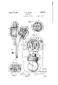
- Fig. 4 is a planiview-showing the seal; xEig; S eisaa longitudinah sectional .view of i'the lock wand its --.-keeper, showing the .-lock Fig. 6; i s:anelevation similartoFig-l but showingthe loekswung open,-;and disclosing the internal construction of the keeper :
- Fig. 7 is a sectional view .on line 7 7 of Fig. .5, disclosing a simple form of locking mechanism Fig. -&is a detail-sectional-view; on, lined-:8
- Fig. 91 s a sectional-view of a detail-of,the ,7
- the keepe ofitheilock is designated by,.ref-erence.@haractor- G, and is suitablysecured to a portionH of the trunk or the ilike, which ,is movable with reference to the portion Bitoxwhich the party A of-thehasp lock :issecured, .,as previously described.
- the lock is designed to be retained in out breaking the seal.
- the lock includes a base plate 23 (see Figs. 5 and 8), which is preferably formed integral with the hasp portion C, this plate being beveled as at 24 to fit a corresponding beveled portion of the face plate 10 of the keeper.
- the plate 23 is hollowed out to re ceive a plate 27, which carries the barrel D preferably detachably secured thereto by means of screws 28.
- the plate 27 is also provided with slots 29 to permit passage of the seal I therethrough, and with guide pins 39 which extend into openings 37 in the trough member 33.
- a heavy disk-shaped casing 31 is seated within the hollowed-out portion of the base plate 23.
- the three members 23, 27 and 31 are secured in fixed relation to each other by means of screws 32, which pass through all three members.
- the disk or casing 31 is slotted nearly to its ends, the slot extending completely through the disk.
- This slot is preferably Widerat the bottom than at the top, so as to retain therein a similarly shaped member I which is inserted from the inner side of the slot in the disk 31 prior to assembling said disk with the members 23 and 27.
- the inserted member includes a trough 33, the bottom of which is slotted as at 34 to provide a key opening.
- This trough is likewise provided with side slots 35.
- a solid seal holding member 36 which is of slightly less length than the trough 33. This solid member is movable with reference to the trough by reason of pins cooperating with the side slots 35 in the trough 33.
- the function of the solid member 36 is to hold the seal I taut, and for this purpose openings 37 are provided, within which are fitted coil springs 38, which react between the bottom of the trough and the seal holding member. As shown guide pins 39 extend into the openings 37 and through the springs 38 from the plate 27. The movement of the seal holding member is limited by the length of the side slots 35 in the trough member.
- the seal I as shown comprises an elongated member, which may be stamped from thin sheet metal, having round openings 41 near its ends and square openings 42 spaced slightly toward the center from the openings 41.
- bolt E is .slidingly mounted within the lock barrel D, and is preferably divided into two side portions 44, with a cut-away portion 45 at the center to permit the seal to pass.
- the look ing mechanism housed within the barrel D is of very simple construction and includes a pair of plates 46 projecting inwardly from the body of the lock barrel, against which coil springs 47 react, their other ends engaging the rear of the bolt E, tending to normally force the same outwardly.
- Attached to the rear end of the bolt is an arm 48 extending rearwardly and hooked as at 49, and including a projection 50 extending substantially at right angles to the direction of movement of the bolt.
- lock mechan sm including the bolt E, may, in fact, be dispensed with entirely and the latches K, in combination with the seal I, may be relied upon entirely for holding the parts in latched engagement.
- the ends of the seal are passed through the slots at the ends of the seal holding member 36, and by pressing inwardly on this member so as to compress the coil springs 38 the ends of the seal may then be secured in place over the pins 43 which pass through the openings 41 in the seal.
- the springs 38 press outwardly against the seal holding member 36 and cause the same to exert a constant pressure upon the seal, holding the seal taut at all times.
- Fig. 5 The pos tion of parts with the seal assembled and the lock about to be closed is clearly indicated in Fig. 5.
- the parts may be secured in latched engagement by pressing the lock inwardly to the position shown in Figs. 1 and 2, the bolt E being engaged in an aperture 54 in the keeper and the hinged latches engaging the openings 42 in the seal, thereby holding the same in fixed position until such time as the seal may be broken or cut.
- the seal passes over the key-hole F, and accordingly it is impossible to retract the bolt so long as the seal remains in position.
- the use of the bolt is not essential, but serves as an additional fa tening means.
- the seal may be readily cut by means of a pair of pliers or other device, whereupon the engagement between the latches of the lock is released.
- the key-hole F is now accessible and the bolt E may be retracted by the use of a key.
- the seals are preferably provided with identitying indicia, such as a serial number, .so that it becomes readily apparent if the seal has been broken and replaced by a new seal. Thus tampering with the lock by an unauthorized person without detection is rendered impossible.
- a lock member having a lock barrel, pins projecting from said barrel, a keeper within which the lock is adapted to be engaged, latches mounted within the keeper, and a seal cooperating with the lock and keeper for holding the lock in latched position, said seal comprising a metal strip having' a pair of apertures adjacent its ends for engagement with the pins on said lock barrel, other apertures intermediate the ends of the seal for engagement by said latches, and yielding means permanently carried by the lock member for holding said seal taut.
Landscapes
- Orthopedics, Nursing, And Contraception (AREA)
Description
0. M. BANGS April 19, 1932.
SEAL LOCK Filed Nov. 28, 1930 2 Sheets-Sheet 1 April 19, 1932. o, -,5 1,854,574
SEAL LOCK Filed Nov. 28, 1930 2 Sheets-Sheet 2 Patented Apr. 19, 1932 OWEN:M..BANS, ,OFjBRQOKLYN, NEW YORK "SEAL LOCK Applicationfilled' November 28,-1930. Serial No.498 89l.
l'llheinventionrelatestoseal locks,-and-the zxpresent application is inthe nature of an imiprovement :over :my Patent .N 0. 1,711,339, .granted April :30, .1929. '5 in any prior ,zpatent zthere is disclosed xbroadlyzthe combination with iailock or latch, (if means :forsealing-the same in latched positionfwhih wmeans includes a sealing strip whose ends are eovered'by the look when in 1 Elatch'e'd t-position, so that ;the lock cannot be iremoved from latched engagement without zbre'al zingathe seal. The specific means .dis- .-closethforthisgpurpose,qaceordingitomygprior ipatent, #included 'a disk-like \member "which was "temporarily held secured to the lock -nieinber byi th'e seal and gripped by latches writliinthe keeper; whereby ithe ilOGk was reitained :inrlatched-engagementas long as the seal remained mnbroken. -When, however,
the seal was br0ken, the disk was separated -fronrtheloc k. When USlHgvSllChfiH arrangenientithereiis danger ofit'he diskbeing lost, and? it is arccordingly the obj ect: of, the present -.invention%to: provide an: imp rovedyand simpli- 1fied;arrangementwvhieh avoids 1 thQEHGCQSSitY ifor :usi-ngthe:removable-disk. This is"ac 4co1np1ished, raccording {to the ipreferred emibodiment .of the present :invention, by i pro- -viding :means whereby the 2 seal itself v is :ig ri-ppe-d by! latchingv means-Within thekeeper wofzthe look.
An important object of the invention -is.-to :provide an improved. and simplified locking :mechan-ism. "Further objects :will be .ap-
vparentifrom the accompanying idrawingssand the following detailedwdescription. setting fo-rthca {preferred embodiment of the inven- "tion.
In theidrawingsz 'Fig. =11 :is r a front elevation showing a a lo ck 1 'o'fethe-"sWinging hasp-E typeto-avhi oh the timproved-sealing deviee is. applied Fig. 2 a ":a view a partly in elevation and rpartly-in section -the lock. being in elevation 'and the-keeper inesection;
eFig. 3 is a-=sectional :view: taken along-the i'irregulari' -line ;8-3vofvFig. 2
Fig. 4 is a planiview-showing the seal; xEig; S eisaa longitudinah sectional .view of i'the lock wand its --.-keeper, showing the .-lock Fig. 6; i s:anelevation similartoFig-l but showingthe loekswung open,-;and disclosing the internal construction of the keeper :Fig. 7 is a sectional view .on line 7 7 of Fig. .5, disclosing a simple form of locking mechanism Fig. -&is a detail-sectional-view; on, lined-:8
,of Eig. 5 ;-:and
Fig. 91s a sectional-view of a detail-of,the ,7
improved-lock.
In the specific embodiment --,0f the inven- :tion' herein dlSClOSQd A-LdEHOtGS; a memberf a ihasp lock fixed ,to one portion ;0f, a trunk or the like, indicated at .B. G denotes ,a swinging hasp member hinge dsto the member A and provided with-iallock case or; barrel =D having a bolt E freciproeably .m ounted therein and adaptedito be actuated by akey inserted through .a key-hole The keepe ofitheilock is designated by,.ref-erence.@haractor- G, and is suitablysecured to a portionH of the trunk or the ilike, which ,is movable with reference to the portion Bitoxwhich the party A of-thehasp lock :issecured, .,as previously described.
:The lock is designed to be retained in out breaking the seal.
Referring to the parts more in, d6. &il,-:-With particularreference to-Figs. 2, 3 311C125, it;will be noted that the keeper comprises a ,face plate 10,-shown as provided with threaded shanks 11 formed integral with the .face plate and extendingthrough the; upper. portion H of the trunk or the like and secured -:thereto by suitable .nuts v12. Preferably 1 formed integral with the face. platewis, 3. cylindrical casing 13 to. which .a rear. plate, 14: i is-suitably secured as by ,means :of screws 15. zCentrally. mounted: on. the rear plate is a partially open, and the seal appliedthereto;
trough-like member which is most clearly shown in Fig. 6. This member comprises a bottom 16 which may be fastened to the plate 14 by means of the screws 17. The trough also includes sides 18, at the ends of which are hingedly mounted the latches K, the hinges being indicated at 19. Hooks 20 are formed at the opposite ends of the latches.
The lock includes a base plate 23 (see Figs. 5 and 8), which is preferably formed integral with the hasp portion C, this plate being beveled as at 24 to fit a corresponding beveled portion of the face plate 10 of the keeper. The plate 23 is hollowed out to re ceive a plate 27, which carries the barrel D preferably detachably secured thereto by means of screws 28. The plate 27 is also provided with slots 29 to permit passage of the seal I therethrough, and with guide pins 39 which extend into openings 37 in the trough member 33. A heavy disk-shaped casing 31 is seated within the hollowed-out portion of the base plate 23. The three members 23, 27 and 31 are secured in fixed relation to each other by means of screws 32, which pass through all three members.
The disk or casing 31 is slotted nearly to its ends, the slot extending completely through the disk. This slot is preferably Widerat the bottom than at the top, so as to retain therein a similarly shaped member I which is inserted from the inner side of the slot in the disk 31 prior to assembling said disk with the members 23 and 27. As shown, the inserted member includes a trough 33, the bottom of which is slotted as at 34 to provide a key opening. This trough is likewise provided with side slots 35. Within the trough is mounted a solid seal holding member 36, which is of slightly less length than the trough 33. This solid member is movable with reference to the trough by reason of pins cooperating with the side slots 35 in the trough 33. The function of the solid member 36 is to hold the seal I taut, and for this purpose openings 37 are provided, within which are fitted coil springs 38, which react between the bottom of the trough and the seal holding member. As shown guide pins 39 extend into the openings 37 and through the springs 38 from the plate 27. The movement of the seal holding member is limited by the length of the side slots 35 in the trough member.
Due to the fact that the trough is of slightly greater length than the solid member inserted therein, slots are provided at the ends of the seal holding member, which permit the seal to pass, as indicated for example in Figs. 1 and 5.
The seal I as shown comprises an elongated member, which may be stamped from thin sheet metal, having round openings 41 near its ends and square openings 42 spaced slightly toward the center from the openings 41.
The length of the seal and the spacing of the openings 41 and 42 are such that when the seal is fitted into position and the seal holding member 36 compressed against the pressure of springs 38, the openings 41 fit over pins 43 mounted in the lock barrel, and when the lock itself is snapped into closed position, the openings 42 will be engaged by the hooks 20 of the latches K.
As shown in Fig. 7, bolt E is .slidingly mounted within the lock barrel D, and is preferably divided into two side portions 44, with a cut-away portion 45 at the center to permit the seal to pass. In the arrangement shown, a single bolt is employed. The look ing mechanism housed within the barrel D is of very simple construction and includes a pair of plates 46 projecting inwardly from the body of the lock barrel, against which coil springs 47 react, their other ends engaging the rear of the bolt E, tending to normally force the same outwardly. Attached to the rear end of the bolt is an arm 48 extending rearwardly and hooked as at 49, and including a projection 50 extending substantially at right angles to the direction of movement of the bolt. This projection 50 is adapted to be engaged by the key 51, whereby the bolt may be retracted against the force of the springs 47 Where a key with a hollow shank is employed, a pin 52 is mounted within the lower portion of the barrel to serve as a guide for the hollow stem of the key. An opening 53 extends through the body of the lock to perm t insertion of the key.
While a specific locking mechanism has been herein described, it is obvious that any form of lock may be employed without departing from the broad features of the invention, although the type described herein is of simple construction and adapted for use in the present combination. The lock mechan sm, including the bolt E, may, in fact, be dispensed with entirely and the latches K, in combination with the seal I, may be relied upon entirely for holding the parts in latched engagement.
The operation of the device is apparent from the foregoing description, but the following summary may assist in an understanding of the invention.
lVhen it is desired to secure the parts in latched engagement, the ends of the seal are passed through the slots at the ends of the seal holding member 36, and by pressing inwardly on this member so as to compress the coil springs 38 the ends of the seal may then be secured in place over the pins 43 which pass through the openings 41 in the seal. The springs 38 press outwardly against the seal holding member 36 and cause the same to exert a constant pressure upon the seal, holding the seal taut at all times.
The pos tion of parts with the seal assembled and the lock about to be closed is clearly indicated in Fig. 5. The parts may be secured in latched engagement by pressing the lock inwardly to the position shown in Figs. 1 and 2, the bolt E being engaged in an aperture 54 in the keeper and the hinged latches engaging the openings 42 in the seal, thereby holding the same in fixed position until such time as the seal may be broken or cut. The seal passes over the key-hole F, and accordingly it is impossible to retract the bolt so long as the seal remains in position. As stated above, however, the use of the bolt is not essential, but serves as an additional fa tening means. To open, the seal may be readily cut by means of a pair of pliers or other device, whereupon the engagement between the latches of the lock is released. The key-hole F is now accessible and the bolt E may be retracted by the use of a key. The seals are preferably provided with identitying indicia, such as a serial number, .so that it becomes readily apparent if the seal has been broken and replaced by a new seal. Thus tampering with the lock by an unauthorized person without detection is rendered impossible.
The details of construction have been minutely described herein for the purpose of illustration, but it will be obvious that such details may be varied without departing from the spirit of the invention.
What I claim is:
1. The combination with a keeper and a lock member adapted to be engaged therein in latched position, of means for sealing said lock in its keeper, said means including a sealing strip surrounding the lock member and having its ends housed within the keeper when the lock is in latched position, said seal having an aperture intermediate its ends, a latch within the keeper adapted to engage said aperture, and yielding means perma nently carried by the lock member for holding the seal taut.
2. In combination with a lock member having a lock barrel and a keeper, a seal surrounding said lock and having its ends secured to the lock barrel, resilient means holding said seal taut, apertures in said seal, and latches within said keeper engaging the apertures in said seal when the lock is moved to closed position, whereby the lock is held in latched position until the seal is broken.
3. In combination with a lock and its keeper, of cooperating means carried by the lock and keeper for sealing the lock in latched position, said means including a seal having apertures adjacent its ends, pins in said lock adapted to be engaged by the apertured ends of the seal, whereby the seal is held in position upon the lock, other apertures intermediate the ends of the seal, latches mounted within the keeper and engaging said last named apertures in the seal when the lock is moved to closed or latched position, and
yielding means permanently carried by the lock member for holding the seal taut.
4. In an apparatus of the character described, in combination, a lock member having a lock barrel, pins projecting from said barrel, a keeper within which the lock is adapted to be engaged, latches mounted within the keeper, and a seal cooperating with the lock and keeper for holding the lock in latched position, said seal comprising a metal strip having' a pair of apertures adjacent its ends for engagement with the pins on said lock barrel, other apertures intermediate the ends of the seal for engagement by said latches, and yielding means permanently carried by the lock member for holding said seal taut.
In testimony whereof I afix my signature.
OWEN M. BANGS.
Priority Applications (1)
| Application Number | Priority Date | Filing Date | Title |
|---|---|---|---|
| US498891A US1854574A (en) | 1930-11-28 | 1930-11-28 | Seal lock |
Applications Claiming Priority (1)
| Application Number | Priority Date | Filing Date | Title |
|---|---|---|---|
| US498891A US1854574A (en) | 1930-11-28 | 1930-11-28 | Seal lock |
Publications (1)
| Publication Number | Publication Date |
|---|---|
| US1854574A true US1854574A (en) | 1932-04-19 |
Family
ID=23982929
Family Applications (1)
| Application Number | Title | Priority Date | Filing Date |
|---|---|---|---|
| US498891A Expired - Lifetime US1854574A (en) | 1930-11-28 | 1930-11-28 | Seal lock |
Country Status (1)
| Country | Link |
|---|---|
| US (1) | US1854574A (en) |
-
1930
- 1930-11-28 US US498891A patent/US1854574A/en not_active Expired - Lifetime
Similar Documents
| Publication | Publication Date | Title |
|---|---|---|
| US4013311A (en) | High security door lock | |
| US924331A (en) | Lock. | |
| US4022503A (en) | Portable security lock | |
| US3869886A (en) | Safety lock | |
| US2613525A (en) | Locking mechanism for window latches | |
| GB992239A (en) | Door chain lock | |
| US1854574A (en) | Seal lock | |
| US3705504A (en) | Chain door latch device | |
| US1564953A (en) | Lock | |
| US1629379A (en) | Door latch | |
| US1844459A (en) | Safety lock | |
| US3482421A (en) | Number lock | |
| US1639535A (en) | Lock | |
| US2301116A (en) | Safety latch shackle | |
| US1984677A (en) | Handcuff | |
| US1195808A (en) | Mato gbgich | |
| GB2037361A (en) | Security Container | |
| GB1516093A (en) | Security device | |
| US597895A (en) | Door or transom stop | |
| US957803A (en) | Show-case lock. | |
| US673183A (en) | Latch. | |
| US997769A (en) | Lock. | |
| GB534096A (en) | Improvements in means for sealing door and like fastenings | |
| US951613A (en) | Seal-holding mechanism for locks. | |
| GB495955A (en) | Improvements in combination locks for handbags and the like |