US1854483A - Holder for collapsible tubes as an article of manufacture - Google Patents
Holder for collapsible tubes as an article of manufacture Download PDFInfo
- Publication number
- US1854483A US1854483A US409172A US40917229A US1854483A US 1854483 A US1854483 A US 1854483A US 409172 A US409172 A US 409172A US 40917229 A US40917229 A US 40917229A US 1854483 A US1854483 A US 1854483A
- Authority
- US
- United States
- Prior art keywords
- holder
- manufacture
- article
- tube
- collapsible tubes
- Prior art date
- Legal status (The legal status is an assumption and is not a legal conclusion. Google has not performed a legal analysis and makes no representation as to the accuracy of the status listed.)
- Expired - Lifetime
Links
- 238000004519 manufacturing process Methods 0.000 title description 5
- 239000002184 metal Substances 0.000 description 4
- 238000003780 insertion Methods 0.000 description 3
- 230000037431 insertion Effects 0.000 description 3
- 238000010276 construction Methods 0.000 description 2
- 230000006978 adaptation Effects 0.000 description 1
- 238000005452 bending Methods 0.000 description 1
- 238000012986 modification Methods 0.000 description 1
- 230000004048 modification Effects 0.000 description 1
- 238000005096 rolling process Methods 0.000 description 1
- 239000000344 soap Substances 0.000 description 1
- 239000000606 toothpaste Substances 0.000 description 1
- 229940034610 toothpaste Drugs 0.000 description 1
- 239000002699 waste material Substances 0.000 description 1
Images
Classifications
-
- B—PERFORMING OPERATIONS; TRANSPORTING
- B65—CONVEYING; PACKING; STORING; HANDLING THIN OR FILAMENTARY MATERIAL
- B65D—CONTAINERS FOR STORAGE OR TRANSPORT OF ARTICLES OR MATERIALS, e.g. BAGS, BARRELS, BOTTLES, BOXES, CANS, CARTONS, CRATES, DRUMS, JARS, TANKS, HOPPERS, FORWARDING CONTAINERS; ACCESSORIES, CLOSURES, OR FITTINGS THEREFOR; PACKAGING ELEMENTS; PACKAGES
- B65D35/00—Pliable tubular containers adapted to be permanently or temporarily deformed to expel contents, e.g. collapsible tubes for toothpaste or other plastic or semi-liquid material; Holders therefor
- B65D35/24—Pliable tubular containers adapted to be permanently or temporarily deformed to expel contents, e.g. collapsible tubes for toothpaste or other plastic or semi-liquid material; Holders therefor with auxiliary devices
- B65D35/32—Winding keys
- B65D35/34—Winding keys connected to, or associated with, tube holders
Definitions
- My invention relates to a holder for c ollapsible tubes such as are used for containing shaving soap, tooth paste and the like, as an article of manufacture.
- the ,objects of my invention are to provide d a device of this class which is new, novel,
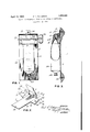
- Figure 1 is a front elevational view of my holder containing a collapsible tube and disposed upon a wall;
- Figure 2 is a perspective view of the 35 stamped and die cut sheet metal from which the holder is formed.
- Figure 3 is a side elevation of the holder in section, containing a usual tube partly in section.
- a strip 1 of sheet metal which is die cut as 55 shown in Fig. 2 to form a rectangular back 2, top 3, and front 4. Said strip, adjacent its side central portions is provided with laterally extending wings, respectively shown as 5 and 6.
- the said top 3 is formed by bending the plate forwardly along the line 7-8 and again along the line 9-10.
- the central portion of the said back 2 has a three sided die cut shown as 11, the upper edges of which terminate along the line 7 8.
- the metal lip 12, formed by this cut is bent backwardly and upwardly to aline with the said back 2, and is perforated as shown as 13 for the holding screw 14.
- the said wings 5 and 6, at their respective side edges 15 and 16 and their top edges 17 and 18 are cut angularly as to the said back 2, so as to conform to the shape of the side edges of the said top 3 and front 4, to which they are soldered, spot welded or other- Wise attached in a desired manner.
- the sides 5 and 6 are provided with alined perforations, shown respectively as 19 and 20, while said side 6 is provided With a slot shown as 21, the center of which coincides with the said perforation 20.
- the lower end portion of the said back 2 is provided centrally vwith a perforation shown as 22, for the insertion of the holding screwl 23.
- the slot 20 provides means for the insertion and withdrawal of a usual key 24, While the said perforations 19 and 20 serve as bearings for the rotation of the said key.
- the said key is of wire, has a flattened central portion and a handle 26 which eX- tends externally as to the side 6.
- the central flattened portion 25 of the key is Slotted as shown at 27 to receive the flat end portion 28 of a usual collapsible tube 29.
- the holder In use the holder will be disposed as described upon a wall, convenient for its use. With the end of the tube 29 disposed therein as described and its cap 30 removed, a slight turn of the key 24 will force a small quantity of the tubes content therefrom, at its usual point of exit. As seen in Fig. 3, ample space is provided for screwing cap 30 on and off. 100
- the back 2 and the front 4 act as a positive means for holding the tube against inadvertant movement.
- a holder for collapsible tubes consisting of a sin le blank of metal comprising a flat plate a apted to be attached flatly to a vertical plain surface, an attaching ear at the upper end of said plate, an open bottomed housing outstanding from the upper portion of said plate, an outwardly curved lip upon the lowerend of the front of said housing, and .5 two ends for said housing, each end formed with an open bearing, and a shaft journaled in said bearings having a split portion for engaging the dat end of the tube, said shaft having a hand turning handle upon one of its ends, said plate constructed of suiicient length to extend below the lower end of a tube engaged by Said shaft, and said shaft so arranged that the engaged tube will constantly contact said lip and said plate.
- one end of said housing is formed with a circular perforation to receive the end of said shaft, and in which the other housing end is formed with a vertical slot having a circular enlargement for permitting the insertion of said shaft.
Landscapes
- Engineering & Computer Science (AREA)
- Mechanical Engineering (AREA)
- Details Of Rigid Or Semi-Rigid Containers (AREA)
Description
April 19, 1932. F, l.. PATTERSON HOLDER FOR COLLAPSIBLE TUBES AS AN ARTICLE OF' MANUFACTURE Filed NOV. 22, 1929 lIl Il..
Patented Apr. 19, 1932 FREI)| L. PATTERSON, OF DUNCAN, OKLAHOMA HOLDER FOR COLLAPSIBLE TUBES AS AN ARTICLE OF MANUFACTURE Application led November 22, 1929. Serial No. 409,172.
My invention relates to a holder for c ollapsible tubes such as are used for containing shaving soap, tooth paste and the like, as an article of manufacture.
,. The ,objects of my invention are to provide d a device of this class which is new, novel,
practical and of utility; which will be adapted for easy disposition upon a wall; which will sustain a collapsible tube, and which will .0 comprise means for rolling and collapsing l said tube upon itself for the purpose of forcing, as desired, portions of its content therefrom; which Will be cheap in manufacture; which will save time; which will render available for use more of the said tubes content than is ordinarily available; which will be sanitary; which will be positive in action; which will prevent Waste and loss of content by breakage due to manual manipulation' of 20 the tube; which will prevent the misplacing of the tube; which will be efficient in. ac coinplishing all the purposes for which it is intended.
A With these and other objects in view as will 25 more fully appear, my invention consists in the construction, novel features, and combination of part-s hereinafter more fully described, pointed out in the claims hereto appended, and illustrated in the accompanying 3g drawings, of which;
Figure 1 is a front elevational view of my holder containing a collapsible tube and disposed upon a wall;
Figure 2 is a perspective view of the 35 stamped and die cut sheet metal from which the holder is formed; and
Figure 3 is a side elevation of the holder in section, containing a usual tube partly in section.
Like characters of reference designate like parts in all the figures.
It is understood that various changes in the form, proportion, size, shape, Weight and other details of construction, Within the scope of my invention may be resorted to without departing from the spirit or broad principle of my invention and without sacrificing any of the advantages thereof; and it is also un- 50 derstood that the drawings are to be interpreted as being illustrative and not restrictive.
One practical embodiment of the invention as illustrated in the drawings comprises:
A strip 1 of sheet metal, Which is die cut as 55 shown in Fig. 2 to form a rectangular back 2, top 3, and front 4. Said strip, adjacent its side central portions is provided with laterally extending wings, respectively shown as 5 and 6. The said top 3 is formed by bending the plate forwardly along the line 7-8 and again along the line 9-10. The central portion of the said back 2 has a three sided die cut shown as 11, the upper edges of which terminate along the line 7 8. The metal lip 12, formed by this cutis bent backwardly and upwardly to aline with the said back 2, and is perforated as shown as 13 for the holding screw 14. The said wings 5 and 6, at their respective side edges 15 and 16 and their top edges 17 and 18 are cut angularly as to the said back 2, so as to conform to the shape of the side edges of the said top 3 and front 4, to which they are soldered, spot welded or other- Wise attached in a desired manner. The sides 5 and 6 are provided with alined perforations, shown respectively as 19 and 20, while said side 6 is provided With a slot shown as 21, the center of which coincides with the said perforation 20. The lower end portion of the said back 2 is provided centrally vwith a perforation shown as 22, for the insertion of the holding screwl 23. The slot 20 provides means for the insertion and withdrawal of a usual key 24, While the said perforations 19 and 20 serve as bearings for the rotation of the said key. The said key is of wire, has a flattened central portion and a handle 26 which eX- tends externally as to the side 6. The central flattened portion 25 of the key is Slotted as shown at 27 to receive the flat end portion 28 of a usual collapsible tube 29.
In use the holder will be disposed as described upon a wall, convenient for its use. With the end of the tube 29 disposed therein as described and its cap 30 removed, a slight turn of the key 24 will force a small quantity of the tubes content therefrom, at its usual point of exit. As seen in Fig. 3, ample space is provided for screwing cap 30 on and off. 100
It may be seen that the back 2 and the front 4 act as a positive means for holding the tube against inadvertant movement.
Obviously, the invention is susceptible of embodiment informs other than that which 5 is illustrated in the accompanying drawings and described herein, and applicable for uses and purposes other than as detailed and I therefore consider as my own all such modifications and adaptations and other uses of the form of the device other than as herein described as fairly fall within the scope of my invention.
Having thus described my invention, what is claimed and desired to be secured by Letters Patent, is:
1. A holder for collapsible tubes, consisting of a sin le blank of metal comprising a flat plate a apted to be attached flatly to a vertical plain surface, an attaching ear at the upper end of said plate, an open bottomed housing outstanding from the upper portion of said plate, an outwardly curved lip upon the lowerend of the front of said housing, and .5 two ends for said housing, each end formed with an open bearing, and a shaft journaled in said bearings having a split portion for engaging the dat end of the tube, said shaft having a hand turning handle upon one of its ends, said plate constructed of suiicient length to extend below the lower end of a tube engaged by Said shaft, and said shaft so arranged that the engaged tube will constantly contact said lip and said plate.
2. rganization as described in claim 1, in which one end of said housing is formed with a circular perforation to receive the end of said shaft, and in which the other housing end is formed with a vertical slot having a circular enlargement for permitting the insertion of said shaft.
- FRED L. PATTERSON.
Priority Applications (1)
| Application Number | Priority Date | Filing Date | Title |
|---|---|---|---|
| US409172A US1854483A (en) | 1929-11-22 | 1929-11-22 | Holder for collapsible tubes as an article of manufacture |
Applications Claiming Priority (1)
| Application Number | Priority Date | Filing Date | Title |
|---|---|---|---|
| US409172A US1854483A (en) | 1929-11-22 | 1929-11-22 | Holder for collapsible tubes as an article of manufacture |
Publications (1)
| Publication Number | Publication Date |
|---|---|
| US1854483A true US1854483A (en) | 1932-04-19 |
Family
ID=23619336
Family Applications (1)
| Application Number | Title | Priority Date | Filing Date |
|---|---|---|---|
| US409172A Expired - Lifetime US1854483A (en) | 1929-11-22 | 1929-11-22 | Holder for collapsible tubes as an article of manufacture |
Country Status (1)
| Country | Link |
|---|---|
| US (1) | US1854483A (en) |
Cited By (1)
| Publication number | Priority date | Publication date | Assignee | Title |
|---|---|---|---|---|
| US2508722A (en) * | 1945-12-28 | 1950-05-23 | Edwin C Loesser | Collapsible tube holder |
-
1929
- 1929-11-22 US US409172A patent/US1854483A/en not_active Expired - Lifetime
Cited By (1)
| Publication number | Priority date | Publication date | Assignee | Title |
|---|---|---|---|---|
| US2508722A (en) * | 1945-12-28 | 1950-05-23 | Edwin C Loesser | Collapsible tube holder |
Similar Documents
| Publication | Publication Date | Title |
|---|---|---|
| US2810503A (en) | Milk carton holder | |
| US2464426A (en) | Glassine gummed paper label holder | |
| US1851722A (en) | Dispensing device | |
| US2583411A (en) | Paper holder especially adapted for toilet papers | |
| US1854483A (en) | Holder for collapsible tubes as an article of manufacture | |
| US3004693A (en) | Roll paper holder and dispenser | |
| US3413049A (en) | Toilet tissue holder | |
| US2472712A (en) | Roll paper dispenser | |
| US1467082A (en) | Stand for paper drinking cups | |
| US2194882A (en) | Tube compressor | |
| US3228618A (en) | Tissue holder | |
| US2085661A (en) | Can holder and server | |
| US2177187A (en) | Menu holder | |
| US2448099A (en) | Toothpick shaker | |
| US1201001A (en) | Brush-holder. | |
| US3025994A (en) | Can opener key | |
| US1463217A (en) | kristofek | |
| CH186224A (en) | Paper holder. | |
| US1309705A (en) | of salem | |
| US1546221A (en) | Device for ejecting paste and cream from collapsible tubes | |
| US1311354A (en) | Bertell w | |
| US1326926A (en) | Card-holder | |
| US1981013A (en) | Wax paper holder and cutter | |
| US1239861A (en) | Check holding and notching device. | |
| US1638613A (en) | Support for collapsible container tubes |