US1854445A - Machine tool - Google Patents
Machine tool Download PDFInfo
- Publication number
- US1854445A US1854445A US538049A US53804931A US1854445A US 1854445 A US1854445 A US 1854445A US 538049 A US538049 A US 538049A US 53804931 A US53804931 A US 53804931A US 1854445 A US1854445 A US 1854445A
- Authority
- US
- United States
- Prior art keywords
- work
- lever
- tool
- carried
- counterweight
- Prior art date
- Legal status (The legal status is an assumption and is not a legal conclusion. Google has not performed a legal analysis and makes no representation as to the accuracy of the status listed.)
- Expired - Lifetime
Links
- 230000008093 supporting effect Effects 0.000 description 3
- 230000006835 compression Effects 0.000 description 1
- 238000007906 compression Methods 0.000 description 1
- 238000010276 construction Methods 0.000 description 1
- 238000004519 manufacturing process Methods 0.000 description 1
Images
Classifications
-
- B—PERFORMING OPERATIONS; TRANSPORTING
- B27—WORKING OR PRESERVING WOOD OR SIMILAR MATERIAL; NAILING OR STAPLING MACHINES IN GENERAL
- B27B—SAWS FOR WOOD OR SIMILAR MATERIAL; COMPONENTS OR ACCESSORIES THEREFOR
- B27B5/00—Sawing machines working with circular or cylindrical saw blades; Components or equipment therefor
- B27B5/16—Saw benches
- B27B5/22—Saw benches with non-feedable circular saw blade
- B27B5/24—Saw benches with non-feedable circular saw blade the saw blade being adjustable according to depth or angle of cut
-
- B—PERFORMING OPERATIONS; TRANSPORTING
- B27—WORKING OR PRESERVING WOOD OR SIMILAR MATERIAL; NAILING OR STAPLING MACHINES IN GENERAL
- B27F—DOVETAILED WORK; TENONS; SLOTTING MACHINES FOR WOOD OR SIMILAR MATERIAL; NAILING OR STAPLING MACHINES
- B27F5/00—Slotted or mortised work
- B27F5/02—Slotting or mortising machines tools therefor
Definitions
- rlhe principal object of the invention is to provide an attachment which may be readily placed upon the common form of vertical spindle Shaper by means of which the use of the shaper may be substantially doubled.
- Another feature of the invention resides in the provision of means for automatically removing one tool from engagement with the work at a predetermined point in the advancement of the work toward the tools while the second tool is permitted to operate upon the work through a longer portion of said advancement.
- the slide 15 may be moved upon the guideways 16 as desired.
- the slide 15 carries a pair of upwardlyextending brackets 22 in turn supporting a horizontal shaft 23.
- a pair of levers 24 are 55 plvotally mounted upon said shaft at a point between their ends.
- the base 26 is also furnished with a dovetail guideway 29 and a motor 30 is slidably mounted therein.
- the said motor maybe horizontally moved upon said guideway by means of a hand wheel 31 65 a-nd a screw 32.
- the motor 30 carries an eX- tended spindle 33 upon which there is carried a rotary cutting tool 34.
- a pair of guide members 41 and 42 are mounted upon the work table 10 ⁇ in the proper position to guide a piece of work 43 into engagement with the two work tools 12 and 34.
- a pair of adjustable rollers 44 and 45 are 95 carried upon an extension of the housing of motor 30 and serve to maintain the work in contact with thev guide members 41 and 42.
- One of the brackets 22 carries a bearing 46 in which there is iXedly mounted a tubular 100 member 47.
- a trip rod 48 is slidably mounted in said tubular member and carries collars 49 and 50 on either side thereof.
- a pair of compression springs 51 and 52 abut. against .I the collars 49 and 50 respectively and against in turn carrying an adjustable Contact piece 55 which projects into the path of travel of the work 43.
- the said trip rod also carries an arm 56 adapted to engage the toggle links 36 and 37 at or near their junction point.
- the collar carries an adjustable stop member 57 which is positioned to 'engage one of the brackets 22 to limit the travel of the trip rod 48.
- the work 43 is advanced toward the tools 12 and 34 and each of said tools cuts a groove therein, as best shown in Figure 3.
- the trip rod 48 is moved to bring the arm 56 into engagement with the toggle links 36 and 37.
- the said toggle links are thereby moved into nonsupporting position and the tool 34 is raised out of contact with the work. Further movement of the work brings the stop member 57 into engagementwith the bracket 22 so that the work can be moved no further.
- the levers 24 are returned to operating position by pulling downwardly on a handle 58 attached to the base 26. rIhe toggle links 36 and 37 then spring into supporting position and the device is ready to operate on a new piece of work.
- a common type of shaper By means of the apparatus described, it is possible for a common type of shaper to be equipped to perform two operations upon the work at the same time although the length of travel of the work for the two operations may be diiferent. More specifically, the length of the cut made by tool 34 depends entirely upon the adjustment of the contact piece while the length of cut of tool 12 may be independently controlled by adjustvment of stop member 57. rIbis is especially useful in the forming of certain members in the manufacture of furniture although the use of the invention is not to be limited to that field.
- a lever pivotally mounted at a point between its ends, a. rotatable cutting tool and means for rotating the same carried upon one end of said lever, a counterweight upon the other end of said lever, a toggle linkage normally maintaining said lever in position for said tool to engage a piece of work advanced against the same, and a trip device engageable by said work at a predetermined point in its advancement and adapted to trip said toggle linkage to permit movement of said lever for moving said tool from work-engaging position.
- a lever pivotally mounted at a point between its ends, a dovetailed member carried by one end of said lever, a sliding base adjustably carried upon said dovetailed member, a motor and a rotary cutting tool mounted on said base and adjustable thereon at right angles to the adjustment of said base upon said dovetailed member, a counterweight upon the other end of said lever, means for normally maintaining said lever in position for said tool to engage a piece of work advanced 59 toward the same, and mechanism engageable by said work at a predetermined point in its advancement for tripping said maintaining means to permit said counterweight to move n said lever to bring said tool out of workengaging position.
Landscapes
- Life Sciences & Earth Sciences (AREA)
- Engineering & Computer Science (AREA)
- Wood Science & Technology (AREA)
- Mechanical Engineering (AREA)
- Forests & Forestry (AREA)
- Milling Processes (AREA)
Description
April 19, 1932. A. .-1. cALPHA MACHINE TOOL Filed May 18, 1931 ATToRNEY.
Patented Apr. 19, 1932 Feier.
TENT
ARTHUR J'. CALPHA, 0F BRAZIL, INDIANA, ASSIGNOR T0 INDIANA FOUNDRY, MA- CHINE & SUPPLY COMPANY, F BRAZIL, INDIANA, A CORPORATION MACHINE TOOL Application led May 18,
This invention relates particularly to an attachment to be used with a vertical spindle Shaper by means of which two tools may be made to work on the Same piece of work Simultaneously although certain features of the invention are applicable to other forms of machine tools.
rlhe principal object of the invention is to provide an attachment which may be readily placed upon the common form of vertical spindle Shaper by means of which the use of the shaper may be substantially doubled.
Another feature of the invention resides in the provision of means for automatically removing one tool from engagement with the work at a predetermined point in the advancement of the work toward the tools while the second tool is permitted to operate upon the work through a longer portion of said advancement.
Other features of the invention reside in the particular arrangement of parts yas particularly pointed out in the following description and claims and the accompanying drawings:
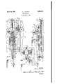
Figure 1 is a plan view of the attachment .fastened upon a work table of a vertical spindle Shaper. Figure 2 is a side elevation of the attachment, and Figure 3 is an end view thereof including portions of the shaper.
In the drawings, there is illustrated a portion of a Shaper having a Substantially fiat work table through which a vertical spindle 11 projects. The said spindle is rotatable by 35 any Well known means and carries a rotary cutting tool 12 in the usual manner. A removable frame 13 is herein shown bolted to the said work table by means of bolts 14 although the same may be secured thereto in any suitable manner. The said frame carries a slide 15 adapted to move horizontally in suitable dovetail guideways 16. The slide 15 carries a bracket 17 threadedly engaged with a screw rod 18. An unthreaded portion of the Said Screw rod passes through a bracket 19 formed lupon the frame 13. Confining collars 2O are provided to prevent longitudinal movement between said screw rod and bracket 19. A hand wheel 21 is carried upon 50 the said screw rod for rotating the same. By
1931. Serial NQ. 538,049
means of this construction, the slide 15 may be moved upon the guideways 16 as desired.
The slide 15 carries a pair of upwardlyextending brackets 22 in turn supporting a horizontal shaft 23. A pair of levers 24 are 55 plvotally mounted upon said shaft at a point between their ends. A dovetailed member 25 1s carried upon one end of said levers and in turn carries a base 26 which is vertically adjustable thereon by means of a hand Wheel 60 27 and Screw 28. The base 26 is also furnished with a dovetail guideway 29 and a motor 30 is slidably mounted therein. The said motor maybe horizontally moved upon said guideway by means of a hand wheel 31 65 a-nd a screw 32. rThe motor 30 carries an eX- tended spindle 33 upon which there is carried a rotary cutting tool 34.
rThe opposite end of one of the levers 24 carries an adjustable counterweight 35 and 70 the said levers are pivotally fastened to the upper end of a toggle link 36 in turn fastened to a second toggle link 37. The lower end of the toggle link 37 is pivotally fastened to a bar 38, the opposite end of which is fastened to the slide 15 and is movable therewith. The bar 38 also carries a bracket vmember 39 upon the upper end of which there is mounted an adjusting screw 40. In the normal operating position of the device, the toggle links assume the positions shown in Figure 2 in which the link 37 abuts against the adjusting screw 40 and `the said links support the levers 24. When pressure is applied to the said toggle links to move the same away from the adjusting screw, the supporting effect upon the levers 24 is lost and the counterweight 35 then moves the levers to elevate. the motor and the tool carried thereby.
A pair of guide members 41 and 42 are mounted upon the work table 10` in the proper position to guide a piece of work 43 into engagement with the two work tools 12 and 34. A pair of adjustable rollers 44 and 45 are 95 carried upon an extension of the housing of motor 30 and serve to maintain the work in contact with thev guide members 41 and 42.
I One of the brackets 22 carries a bearing 46 in which there is iXedly mounted a tubular 100 member 47. A trip rod 48 is slidably mounted in said tubular member and carries collars 49 and 50 on either side thereof. A pair of compression springs 51 and 52 abut. against .I the collars 49 and 50 respectively and against in turn carrying an adjustable Contact piece 55 which projects into the path of travel of the work 43. The said trip rod also carries an arm 56 adapted to engage the toggle links 36 and 37 at or near their junction point.
The collar carries an adjustable stop member 57 which is positioned to 'engage one of the brackets 22 to limit the travel of the trip rod 48.
In the operation of the device, the work 43 is advanced toward the tools 12 and 34 and each of said tools cuts a groove therein, as best shown in Figure 3. Vvlhen the work engages the contact piece 55, the trip rod 48 is moved to bring the arm 56 into engagement with the toggle links 36 and 37. The said toggle links are thereby moved into nonsupporting position and the tool 34 is raised out of contact with the work. Further movement of the work brings the stop member 57 into engagementwith the bracket 22 so that the work can be moved no further. When the work has been withdrawn, the levers 24 are returned to operating position by pulling downwardly on a handle 58 attached to the base 26. rIhe toggle links 36 and 37 then spring into supporting position and the device is ready to operate on a new piece of work.
By means of the apparatus described, it is possible for a common type of shaper to be equipped to perform two operations upon the work at the same time although the length of travel of the work for the two operations may be diiferent. More specifically, the length of the cut made by tool 34 depends entirely upon the adjustment of the contact piece while the length of cut of tool 12 may be independently controlled by adjustvment of stop member 57. rIbis is especially useful in the forming of certain members in the manufacture of furniture although the use of the invention is not to be limited to that field.
The invention claimed is:
l. In combination with a shaper having a substantially fiat work table and a. vertical spindle projecting above said work table and carrying a rotary working tool, a removable frame bolted to said work table, a bracket carried thereby, a lever pivotally mounted upon said bracket at a point between its ends, a second rotary cutting tool and means for rotating the same carried upon one end of said lever, a counterweight carried upon the opposite end of said lever, means for normally maintaining said lever in position for said second tool to engage a piece of work advanced to engage said first cutting tool, and mechanism engageable by said work at a predetermined point in its advancement for tripping said maintaining means to permit said counterweight to move said lever to bring said second tool out of work-engaging position.
2. n combination with a sha-per having a substantially fiat work table and a vertical spindle proj ecting above said work table and carrying a rotary working tool, a. removable frame bolted to said work table, a bracket slidably carried thereby, means for adj ustabiy positioning said bracket, a lever pivotally mounted upon said bracket at a point between its ends, a second rotary cutting tool and means for rotating the same carried upon one end of said lever, a counterweight carried upon the opposite end of said lever, means for normally maintaining said lever in position for said second tool to engage a piece of work advanced to engage said first cutting tool, and mechanism engageable by said work at a predetermined point in its advancement for tripping said maintaining means to permit said counterweight to move said lever to bring said second tool out of work-engaging position.
3. ln combination with a shaper having a substantially fiat work table and a vertical spindle projecting above said work table and carrying a rotary working tool, a removable frame bolted to said work table, a bracket carried thereby, a lever pivotally mounted upon said bracket at a point between its ends, a second rotary cutting tool and means for rotating the same carried upon one end of said lever, a counterweight carried upon the `opposite end of said lever, a toggle linkage for normally maintaining said lever in position for said second tool to engage a piece of work advanced to engage said first cutting tool, and mechanism engageable by said work at a predetermined point in its advancement for tripping said toggle linkage to permit said counterweight to move said lever to bring said second tool out of work-engaging position.
4. In combination with a shaper having a substantially dat work table and av vertical spindle projecting above said work table and carrying a rotary working tool, a removable frame bolted to said work table, a bracket carried thereby, a lever pivotally mounted upon said bracket at a point between its ends, a dovetailed member carried by one end of said lever, a sliding base adjustably carried upon said dovetailed member, a motor and a second rotary cutting tool vmounted on said base and adjustable thereon at right `an- 'gies to the adjustment of said base upon said dovetailed member, a counterweight carried upon the opposite end of said lever, means for normally maintaining said lever in position for said second tool to engage a piece of work advanced to engage said rst cutting tool, and mechanism engageable by said 5 work at a predetermined point in its advancement for tripping said maintaining means to permit said counterweight to move said lever to bring said second tool out of worlrengagin position. lo 5. In a mac ine tool, the combination of a lever pivotally mounted at a point between its ends, a rotatable cutting tool and means for rotating the same carried upon one end of said lever, a counterweight upon the other end of said lever, means for normally maintaining said lever in position for said tool to engage a piece of work advanced toward the same, and mechanism engageable by said work at a predetermined point in its advancement for tripping said maintaining means to permit said counterweight to move said lever to bring said tool out of work-engaging position.
6. In a machine tool, the combination of a lever pivotally mounted at a point between its ends, a. rotatable cutting tool and means for rotating the same carried upon one end of said lever, a counterweight upon the other end of said lever, a toggle linkage normally maintaining said lever in position for said tool to engage a piece of work advanced against the same, and a trip device engageable by said work at a predetermined point in its advancement and adapted to trip said toggle linkage to permit movement of said lever for moving said tool from work-engaging position.
7 In a machine tool, the combination of a lever pivotally mounted at a point between its ends, a dovetailed member carried by one end of said lever, a sliding base adjustably carried upon said dovetailed member, a motor and a rotary cutting tool mounted on said base and adjustable thereon at right angles to the adjustment of said base upon said dovetailed member, a counterweight upon the other end of said lever, means for normally maintaining said lever in position for said tool to engage a piece of work advanced 59 toward the same, and mechanism engageable by said work at a predetermined point in its advancement for tripping said maintaining means to permit said counterweight to move n said lever to bring said tool out of workengaging position.
In witness whereof, I have hereunto afxed my signature.
ARTHUR J. CALPI-IA.
Priority Applications (1)
| Application Number | Priority Date | Filing Date | Title |
|---|---|---|---|
| US538049A US1854445A (en) | 1931-05-18 | 1931-05-18 | Machine tool |
Applications Claiming Priority (1)
| Application Number | Priority Date | Filing Date | Title |
|---|---|---|---|
| US538049A US1854445A (en) | 1931-05-18 | 1931-05-18 | Machine tool |
Publications (1)
| Publication Number | Publication Date |
|---|---|
| US1854445A true US1854445A (en) | 1932-04-19 |
Family
ID=24145223
Family Applications (1)
| Application Number | Title | Priority Date | Filing Date |
|---|---|---|---|
| US538049A Expired - Lifetime US1854445A (en) | 1931-05-18 | 1931-05-18 | Machine tool |
Country Status (1)
| Country | Link |
|---|---|
| US (1) | US1854445A (en) |
-
1931
- 1931-05-18 US US538049A patent/US1854445A/en not_active Expired - Lifetime
Similar Documents
| Publication | Publication Date | Title |
|---|---|---|
| US481983A (en) | Work-holder and safety-guard for universal woodworkers | |
| US1802096A (en) | Planer attachment for jointers | |
| US2180743A (en) | Machine for cutting tile and the like | |
| US1854445A (en) | Machine tool | |
| US2377437A (en) | Machine for cutting articles | |
| US1895990A (en) | Hand drill | |
| GB639640A (en) | Improvements in screw driving machines | |
| US1622822A (en) | Universal follow rest | |
| US1422971A (en) | Woodworking machine | |
| US1556852A (en) | Profiling machine | |
| US2589576A (en) | Sawing machine | |
| US452495A (en) | lindner | |
| US1560105A (en) | Wood-cutting machine | |
| US1221708A (en) | Rail-drilling machine. | |
| US1163098A (en) | Woodworking machinery. | |
| US2218470A (en) | Slug cutting machine | |
| US645329A (en) | Woodworking-machine. | |
| US516677A (en) | Automatic feed for band sawing-machines | |
| US1932185A (en) | Automatic chuck for billets and the like | |
| GB787869A (en) | Universal wood or metal working machine | |
| GB1088278A (en) | Apparatus for machining panel-shaped workpieces | |
| US2207786A (en) | Feed mechanism for profiling machines | |
| GB139990A (en) | Apparatus for setting the dies of wire drawing machines | |
| US1475255A (en) | Rapid traverse and feed control for boring mills | |
| US615313A (en) | Milling-machine |