US1854422A - Hauling mechanism - Google Patents
Hauling mechanism Download PDFInfo
- Publication number
- US1854422A US1854422A US366461A US36646129A US1854422A US 1854422 A US1854422 A US 1854422A US 366461 A US366461 A US 366461A US 36646129 A US36646129 A US 36646129A US 1854422 A US1854422 A US 1854422A
- Authority
- US
- United States
- Prior art keywords
- motor
- drum
- bearing
- housing
- gear
- Prior art date
- Legal status (The legal status is an assumption and is not a legal conclusion. Google has not performed a legal analysis and makes no representation as to the accuracy of the status listed.)
- Expired - Lifetime
Links
Images

Classifications
-
- B—PERFORMING OPERATIONS; TRANSPORTING
- B66—HOISTING; LIFTING; HAULING
- B66D—CAPSTANS; WINCHES; TACKLES, e.g. PULLEY BLOCKS; HOISTS
- B66D1/00—Rope, cable, or chain winding mechanisms; Capstans
- B66D1/60—Rope, cable, or chain winding mechanisms; Capstans adapted for special purposes
- B66D1/74—Capstans
- B66D1/7421—Capstans having a vertical rotation axis
- B66D1/7426—Capstans having a vertical rotation axis driven by motor only
-
- B—PERFORMING OPERATIONS; TRANSPORTING
- B66—HOISTING; LIFTING; HAULING
- B66D—CAPSTANS; WINCHES; TACKLES, e.g. PULLEY BLOCKS; HOISTS
- B66D1/00—Rope, cable, or chain winding mechanisms; Capstans
- B66D1/60—Rope, cable, or chain winding mechanisms; Capstans adapted for special purposes
- B66D1/74—Capstans
- B66D1/7484—Details concerning gearing arrangements, e.g. multi-speed
Definitions
- This invention relates to hauling mechanisms, and more particularly to hauling mechanisms of the power driven capstan type.
- An object of my invention is to provide an improved haulage mechanism.
- a further object of my invention is to provide an improved haulage mechanism of the capstan type in which substantial support is provided the winding head.
- a still further object of my invention is to provide ⁇ an improved haulage mechanism of the capstan'type in which rotatable support for the winding head closely adjacent the rope engaging portion is afforded in an improved manner.
- Fig. 1 is a central vertical section (certain small details being shown in elevation) through the illustrative embodiment of my invention.
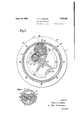
- Fig. 2 is a transverse section o n 2,-2 of Fig. 1.
- Fig. 3 is a horizontal section on line ,3 3 of Fig. 1.
- base 1 of the illustrative embodiment of my invention supports a cylindrical casing 2 which surrounds a motor housing 8 which is bored to provide intercommunicating rotor chambers 8'r1 and 8b of the type more fully illustrated in my above mentioned patent.
- These chambers are closed at their lower ends by a common closure plate 3 in which are provided bearings 4 and 5 for the lower ends of the shafts 12 and 13 of intermeshing rotors 6l and 7.
- the rotors 6 and 7 are provided with intermeshing teeth cooperating to form expansion chambers to which fluid pressure may be admitted in a manner commonly followed in .this type of motor, as through an inlet I.
- a plate 49 is vsecured to the base 1 vscrews .5.0 .to protect the line 1929. serial No. 366,461.v
- a second closure plate 9 which carries ball bearingslO and 11 for the upper ends of the rotor shafts 12 and 13.
- Registering apertures (not shown) through both the'casing 2 and the housing 8 provide for exhaust of the motive iiuicl. Drainage is established between the upper and lower ends of the rotors through passages 6a and 7a, and the rotor'chambers are drained through a passage 6b provided with 'a drain cock (not shown).
- the space above plate 49 is vented through a passage 49a, also preferably con'- trolled by a drain cock not shown.
- a race 14 Surrounding the upper portion of the housing 8 is a race 14 which forms part of a roller bearing 15, the outer race 16 of the same being carried by the lower flange 17 of the rope winding portion or drum 18 of the capstan head.
- the lower inner edge of the flange 17 is rabbeted and the upper outer portion of the base 2 is correspondingly rabbeted to afford an annular chamber 19 for a packing ring 19a which prevents leakage of cil from the roller bearing 15.
- An aperture is provided centrally of the upper plate 9 and the boss 20 of a member 21 is disposed within this aperture.
- the member 21 supports a ball bearing 22 in which kis journaled oneend of a short shaft 23.
- a small gear 30 is secured to the shaft 23 adjacent the ball bearing 29, it being obvious that if preferred the gear 30 may be formed integrally with the shaft 23.
- the gear 30 meshes with a gear 31 mounted on and secured to the lower endy of a stub shaft 32, .Which is rotatably supported in spaced ball bearings 33, 34, carried by the member 27.
- a gear 35 is secured to the shaft 32 or, if desired, may be formed integrally therewith.
- the gear 35 meshes with an idler gear 36, the latter meshing with an internal gear 37.
- the idler gear 36 is rotatably mounted on a stub shaft 38 supported by the member 27.
- the upper portion 39 (see Fig. l) of the member 27 carries a ball bearing 40 which cooperates with an opening in a cover member41 which is formed integrally with the internal gear 3,7..
- the pe* ripheral radial flange 42 on the cover member is secured by bolts 43,- toa corresponding iange 44 extending radially from the upper end of the member 18.
- Acap 45 is secured to the cover member 41V by screws 46, the cap serving additionally to hold in place the-outer race lof the bali7 bearing 40.
- a washer 47 and cap screw 48 vserve to hold the inner race of this ball bearing 40 in position.
- the ball bearingy 40- and the rol-ler bearing 15, provide rotatable support for the capstan head: including the drum member 18; Due to the improved constructionI of the positioning means for-the'balll bearing 40, the latter carries the major portion of the weight of the capstan head and drum.
- the strain induced by hauling in. on the rope is principally taken up by the roller bearing 15 which is closely adjacent ythe rope winding surface of the drum member 18. It is therefore apparent that I haveprovid'ed an improved' haulage mechanism of the capstan type which provides rotatable supporty for the capstan heady closely adjacent the application of the pulling strain At the same time the mechanism is compact in spite of the fact that the gearing provides ample reduction in the winding speed of the capstan.
- a power driven: capstan com-prising a base housing a motor, a winding drum rotatable on a vertical axis and having its lower portion surrounding said housing, said base providing-on its periphery a bearing for receiving from the drum the greater portion of the strain of winding, a non-rotatable bearing support projecting upwardly from and carriedl by said base for rotatably supporting the upper end of said drum, and operative driving connections between said motor anddrum including gearing supported above said motor ⁇ between the ends of, the drum.
- a power driven capstan comprising a cylindrical base housing a motor, a winding drum rotatable on a vertical axis and having its lower portion surrounding and journaled on said housing, means providing a nonrotatable and rigid bearing support for the upper end of said drum, and operative driving connections between said motor and drum including reduction gearing disposed above the plane of the journal between the drum and housing and between the ends of the drum.
- a power driven capstan comprising a frame, amotor housed therein with its axis vertical, a winding drum rotatable on a vertical axis and surrounding at least a portion of said' moto-r, and operative driving connections between said motor and drum, said frame providing a non-rotatable spindle for rotatably mounting said drum and said frame having in addition a bearing on its periphery for receiving from the drum the greater portion of the strain of winding, and said operative driving connections between said motor and drum including drum driving reduction gearing disposed above said motor.
- a power driven capstan y comprising a frame, a motor housed therein with its axis vertical, a winding drum rotatable on a vertical axis and surrounding at least a portion of said motor, and operative driving connections between said motor and drum, said frame providing spaced bearings fory said drum, the upper bearing being formed as a fixed spindle and the lowerbearing journaling the lower portion of said drum on the periphery of said frame so that the frame receives from the lower portion of the drum the greater portion of the strain of winding, and said operative driving connections between said motor and drum including drum driving reduction gea-ring disposed above said motor.
- a motor a gear housing mounted upon the motor, gearing in said housing driven by said motor', said housing having at the upper end thereof rigid means providing a bearing to support axial and 'radial thrusts, a gear mounted on'said bearing and driven by said gearing, and a drum suspended from said gear and driven thereby, said drum enclosing ⁇ said housing and j ournaled at its lower end on the motor.
- a motor In a haulage mechanism, a motor, a bearing surrounding said motor and a second coaxial bearing materially above the motor and having a rigid support mounted upon Y the motor, reduction gearing connected with the motor and supported above the latter but below the second bearing, and a drum journaled on said bearings and operatively connected with said reduction gearing.
- a motor a bearing having a support disposed adjacent said motor, said bearing being arranged primarily to care Jfor radial loads, a second coaxial bearing supported above the motor and having a support in rigid relation to the rst bearing support, Said second bearing providing for support of its load in an axial direction, reduction gearing Connected with the motor and arranged above the motor and rst bearing but below the second bearing, and a drum engaging both said bearings and suspended Jfrom the second mentioned bear-
Landscapes
- Engineering & Computer Science (AREA)
- Mechanical Engineering (AREA)
- Connection Of Motors, Electrical Generators, Mechanical Devices, And The Like (AREA)
Description
April 19, 1932.
R. c. osGooD 1,854,422
HAULING MECHANI SM Filed May 27, 1929 2 sheets-sheet 1 ATTORNEY April 19, 1932. R. c. osGooD 1,854,422
HAULING MECHANI SM Filed May 27, 1929 2 sheets-sheet 2 ,I l, g l .l/vvE/vToR v l ROBERT C 056000 MMA-mm- ATTORNEY Patented Apr. 19, 1932 UNITED STATES PATENT oFFicn u ROBERT C. OSGOOD, 0F CLAREMONT, NEW HAMPSHIRE, ASSIGNOR TO SULLIVAN MACHINERY COMPANY, A CORPORATION OF MASSACHUSETTS murrine` MEcHANrsM Application filed. May 27,
This invention relates to hauling mechanisms, and more particularly to hauling mechanisms of the power driven capstan type.
An object of my invention is to provide an improved haulage mechanism. A further object of my invention is to provide an improved haulage mechanism of the capstan type in which substantial support is provided the winding head. A still further object of my invention is to provide `an improved haulage mechanism of the capstan'type in which rotatable support for the winding head closely adjacent the rope engaging portion is afforded in an improved manner. Other objects and advantages of my invention will hereinafter more fully appear.
Inrcertain aspects, the mechanism disclosed herein is an improvement over the somewhat similar mechanism disclosed in my prior Patent 1,665,068, patented April 3, 1928.
In the accompanying drawings I have shown for purposesof illustration one form which mysinvention may assume in practice.
Fig. 1 is a central vertical section (certain small details being shown in elevation) through the illustrative embodiment of my invention.
Fig. 2 is a transverse section o n 2,-2 of Fig. 1.
Fig. 3 is a horizontal section on line ,3 3 of Fig. 1.
rI he base 1 of the illustrative embodiment of my invention supports a cylindrical casing 2 which surrounds a motor housing 8 which is bored to provide intercommunicating rotor chambers 8'r1 and 8b of the type more fully illustrated in my above mentioned patent. These chambers are closed at their lower ends by a common closure plate 3 in which are provided bearings 4 and 5 for the lower ends of the shafts 12 and 13 of intermeshing rotors 6l and 7. The rotors 6 and 7 are provided with intermeshing teeth cooperating to form expansion chambers to which fluid pressure may be admitted in a manner commonly followed in .this type of motor, as through an inlet I. A plate 49 is vsecured to the base 1 vscrews .5.0 .to protect the line 1929. serial No. 366,461.v
the lower end of the motor, the plate 49 being spaced from the bottom of the base as shown in Fig. 1. Upon the top of the housing 8 is mounted a second closure plate 9 which carries ball bearingslO and 11 for the upper ends of the rotor shafts 12 and 13. Registering apertures (not shown) through both the'casing 2 and the housing 8 provide for exhaust of the motive iiuicl. Drainage is established between the upper and lower ends of the rotors through passages 6a and 7a, and the rotor'chambers are drained through a passage 6b provided with 'a drain cock (not shown). The space above plate 49 is vented through a passage 49a, also preferably con'- trolled by a drain cock not shown. i Surrounding the upper portion of the housing 8 is a race 14 which forms part of a roller bearing 15, the outer race 16 of the same being carried by the lower flange 17 of the rope winding portion or drum 18 of the capstan head. The lower inner edge of the flange 17 is rabbeted and the upper outer portion of the base 2 is correspondingly rabbeted to afford an annular chamber 19 for a packing ring 19a which prevents leakage of cil from the roller bearing 15.
An aperture is provided centrally of the upper plate 9 and the boss 20 of a member 21 is disposed within this aperture. The member 21 supports a ball bearing 22 in which kis journaled oneend of a short shaft 23. An
A small gear 30 is secured to the shaft 23 adjacent the ball bearing 29, it being obvious that if preferred the gear 30 may be formed integrally with the shaft 23. The gear 30 meshes with a gear 31 mounted on and secured to the lower endy of a stub shaft 32, .Which is rotatably supported in spaced ball bearings 33, 34, carried by the member 27. A gear 35 is secured to the shaft 32 or, if desired, may be formed integrally therewith.
As best seen in Fig. 2, the gear 35 meshes with an idler gear 36, the latter meshing with an internal gear 37.. The idler gear 36 is rotatably mounted on a stub shaft 38 supported by the member 27. The upper portion 39 (see Fig. l) of the member 27 carries a ball bearing 40 which cooperates with an opening in a cover member41 which is formed integrally with the internal gear 3,7.. The pe* ripheral radial flange 42 on the cover member is secured by bolts 43,- toa corresponding iange 44 extending radially from the upper end of the member 18. Acap 45 is secured to the cover member 41V by screws 46, the cap serving additionally to hold in place the-outer race lof the bali7 bearing 40. A washer 47 and cap screw 48 vserve to hold the inner race of this ball bearing 40 in position.
It will now be apparent that the ball bearingy 40- and the rol-ler bearing 15, provide rotatable support for the capstan head: including the drum member 18; Due to the improved constructionI of the positioning means for-the'balll bearing 40, the latter carries the major portion of the weight of the capstan head and drum. The strain induced by hauling in. on the rope is principally taken up by the roller bearing 15 which is closely adjacent ythe rope winding surface of the drum member 18. It is therefore apparent that I haveprovid'ed an improved' haulage mechanism of the capstan type which provides rotatable supporty for the capstan heady closely adjacent the application of the pulling strain At the same time the mechanism is compact in spite of the fact that the gearing provides ample reduction in the winding speed of the capstan.
While I have in this application specificallydescribed one forml which my invention may assume in practice, it will be understood that this form of the samev is shown for purposes of illustration andthat the invention may be modified andv embodied in various other forms without departing from its spirit or the scope ofthe appended claims.y
What I claim as new and desire to secure by Letters Patent is.:
1. A power driven: capstan com-prising a base housing a motor, a winding drum rotatable on a vertical axis and having its lower portion surrounding said housing, said base providing-on its periphery a bearing for receiving from the drum the greater portion of the strain of winding, a non-rotatable bearing support projecting upwardly from and carriedl by said base for rotatably supporting the upper end of said drum, and operative driving connections between said motor anddrum including gearing supported above said motor `between the ends of, the drum.
2. A power driven capstan comprising a cylindrical base housing a motor, a winding drum rotatable on a vertical axis and having its lower portion surrounding and journaled on said housing, means providing a nonrotatable and rigid bearing support for the upper end of said drum, and operative driving connections between said motor and drum including reduction gearing disposed above the plane of the journal between the drum and housing and between the ends of the drum.
3. A power driven capstan comprising a frame, amotor housed therein with its axis vertical, a winding drum rotatable on a vertical axis and surrounding at least a portion of said' moto-r, and operative driving connections between said motor and drum, said frame providing a non-rotatable spindle for rotatably mounting said drum and said frame having in addition a bearing on its periphery for receiving from the drum the greater portion of the strain of winding, and said operative driving connections between said motor and drum including drum driving reduction gearing disposed above said motor.
4'. A power driven capstan ycomprising a frame, a motor housed therein with its axis vertical, a winding drum rotatable on a vertical axis and surrounding at least a portion of said motor, and operative driving connections between said motor and drum, said frame providing spaced bearings fory said drum, the upper bearing being formed as a fixed spindle and the lowerbearing journaling the lower portion of said drum on the periphery of said frame so that the frame receives from the lower portion of the drum the greater portion of the strain of winding, and said operative driving connections between said motor and drum including drum driving reduction gea-ring disposed above said motor.
5. In a haulage mechanism, a motor, a gear housing mounted upon the motor, gearing in said housing driven by said motor', said housing having at the upper end thereof rigid means providing a bearing to support axial and 'radial thrusts, a gear mounted on'said bearing and driven by said gearing, and a drum suspended from said gear and driven thereby, said drum enclosing` said housing and j ournaled at its lower end on the motor.
6. In a haulage mechanism, a motor, a bearing surrounding said motor and a second coaxial bearing materially above the motor and having a rigid support mounted upon Y the motor, reduction gearing connected with the motor and supported above the latter but below the second bearing, and a drum journaled on said bearings and operatively connected with said reduction gearing.
7. In a haulage mechanism, a motor, a bearing having a support disposed adjacent said motor, said bearing being arranged primarily to care Jfor radial loads, a second coaxial bearing supported above the motor and having a support in rigid relation to the rst bearing support, Said second bearing providing for support of its load in an axial direction, reduction gearing Connected with the motor and arranged above the motor and rst bearing but below the second bearing, and a drum engaging both said bearings and suspended Jfrom the second mentioned bear-
Priority Applications (1)
| Application Number | Priority Date | Filing Date | Title |
|---|---|---|---|
| US366461A US1854422A (en) | 1929-05-27 | 1929-05-27 | Hauling mechanism |
Applications Claiming Priority (1)
| Application Number | Priority Date | Filing Date | Title |
|---|---|---|---|
| US366461A US1854422A (en) | 1929-05-27 | 1929-05-27 | Hauling mechanism |
Publications (1)
| Publication Number | Publication Date |
|---|---|
| US1854422A true US1854422A (en) | 1932-04-19 |
Family
ID=23443098
Family Applications (1)
| Application Number | Title | Priority Date | Filing Date |
|---|---|---|---|
| US366461A Expired - Lifetime US1854422A (en) | 1929-05-27 | 1929-05-27 | Hauling mechanism |
Country Status (1)
| Country | Link |
|---|---|
| US (1) | US1854422A (en) |
Cited By (2)
| Publication number | Priority date | Publication date | Assignee | Title |
|---|---|---|---|---|
| DE908844C (en) * | 1942-01-29 | 1954-04-12 | Eickhoff Geb | Schraemmaschine with adjustable and reversible fluid gear |
| US2826939A (en) * | 1954-08-02 | 1958-03-18 | Otto E Dever | Capstan |
-
1929
- 1929-05-27 US US366461A patent/US1854422A/en not_active Expired - Lifetime
Cited By (2)
| Publication number | Priority date | Publication date | Assignee | Title |
|---|---|---|---|---|
| DE908844C (en) * | 1942-01-29 | 1954-04-12 | Eickhoff Geb | Schraemmaschine with adjustable and reversible fluid gear |
| US2826939A (en) * | 1954-08-02 | 1958-03-18 | Otto E Dever | Capstan |
Similar Documents
| Publication | Publication Date | Title |
|---|---|---|
| US1951875A (en) | Power transmission mechanism | |
| GB1441978A (en) | Rope winch | |
| US3788607A (en) | Winch mechanism | |
| US1854422A (en) | Hauling mechanism | |
| US2795155A (en) | Speed reducers | |
| US2066779A (en) | Hauling drum | |
| US1386792A (en) | Rotary blower | |
| US2905010A (en) | Electrically operated self-contained speed change mechanism | |
| US2941411A (en) | Belt conveyor | |
| US2496754A (en) | Suspended type hoist | |
| US2278795A (en) | Hydraulic pump | |
| US2488833A (en) | Stacker drive | |
| JP2571579B2 (en) | Device for driving a vertical roll of a universal roll stand | |
| US2422933A (en) | Gear drive | |
| US1836225A (en) | Speed reducing pulley | |
| US1873380A (en) | Power mechanism for wells | |
| US2655222A (en) | Means for lubricating chains | |
| US1582075A (en) | Hoist driving gear | |
| US2039870A (en) | Hoist | |
| US1665068A (en) | Hauling mechanism | |
| US2083954A (en) | Cable winding apparatus | |
| US3306553A (en) | Hoist drum | |
| US1909507A (en) | Crane turntable and gear housing | |
| US1740707A (en) | Hoist | |
| US1834598A (en) | Hoist |