US1854413A - Cotton picker unit - Google Patents
Cotton picker unit Download PDFInfo
- Publication number
- US1854413A US1854413A US494236A US49423630A US1854413A US 1854413 A US1854413 A US 1854413A US 494236 A US494236 A US 494236A US 49423630 A US49423630 A US 49423630A US 1854413 A US1854413 A US 1854413A
- Authority
- US
- United States
- Prior art keywords
- head
- finger
- picker
- stem
- cotton
- Prior art date
- Legal status (The legal status is an assumption and is not a legal conclusion. Google has not performed a legal analysis and makes no representation as to the accuracy of the status listed.)
- Expired - Lifetime
Links
- 229920000742 Cotton Polymers 0.000 title description 10
- 241000219146 Gossypium Species 0.000 description 9
- 230000006378 damage Effects 0.000 description 3
- 239000000835 fiber Substances 0.000 description 3
- 240000002024 Gossypium herbaceum Species 0.000 description 2
- 235000004341 Gossypium herbaceum Nutrition 0.000 description 2
- 208000027418 Wounds and injury Diseases 0.000 description 2
- 230000003247 decreasing effect Effects 0.000 description 2
- 208000014674 injury Diseases 0.000 description 2
- 239000002184 metal Substances 0.000 description 2
- 239000002023 wood Substances 0.000 description 2
- 241000196324 Embryophyta Species 0.000 description 1
- 239000003831 antifriction material Substances 0.000 description 1
- 230000000694 effects Effects 0.000 description 1
- 239000000463 material Substances 0.000 description 1
- 230000001681 protective effect Effects 0.000 description 1
- 230000000630 rising effect Effects 0.000 description 1
- 230000001131 transforming effect Effects 0.000 description 1
Images
Classifications
-
- A—HUMAN NECESSITIES
- A01—AGRICULTURE; FORESTRY; ANIMAL HUSBANDRY; HUNTING; TRAPPING; FISHING
- A01D—HARVESTING; MOWING
- A01D46/00—Picking of fruits, vegetables, hops, or the like; Devices for shaking trees or shrubs
- A01D46/08—Picking of fruits, vegetables, hops, or the like; Devices for shaking trees or shrubs of cotton
- A01D46/14—Picking of fruits, vegetables, hops, or the like; Devices for shaking trees or shrubs of cotton using lint-from-plant pickers
Definitions
- the present invention relates to that type of cotton picking machine having pronged ngers and adapted to rotate first in one d1- rection and then in the other for the purpose of withdrawing fibre from the boll and afterwards ldischarging it; and the object of the present invention is to produce a simple and durable picking element of this kind that will successfully pick the cotton bre and deliver it at a receiving point, Without danger of injury to the stems or leaves of the cotton plant,
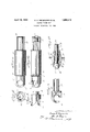
- Figures 1 and 2 are side elevations of a pickerfunit and its bearing sleeve detached from the machine, the picker head being shown in different angular positions, and a ilfragment 'of'theidriving end being shown in section in Fig. 2;- F ig. 3 is a side View of the head of the linger showing still another angu- ,lar position; Fig. 4 is an end view of the finger; Fig. 5 is a section taken on line 5 5 of Fig. 4E; and Fig. 6 is a View on a smaller scale'than Figs. 1 to 5, partly in section and partly in elevation, illustrating the means I for mounting the finger.
- the finger illustrated in the drawings consists of a head 1 fixed to or integral with one end of a cylindrical stem 2 having at the free end a' short section 3 of reduced diameter and preferably lroughenedv on the surface.
- the head first takes the form of a cylindrical block.
- Two deep diagonal cuts are then '-madethrough thelend of the head, 180 apart, fthese cu-ts extending through 'lthe cylindrical block and transforming it into two prongsor hooks 4 pointedat their outer ends and increasing' gradually. in width toward-their inner ends or bases.
- the head first takes the form of a cylindrical block.
- Two deep diagonal cuts are then '-madethrough thelend of the head
- angular width of the base of eachihook is Vapnl proximately 1800.
- theprongs or hooks have their outer faces disposed in a. cylindrical surface coaxial with the finger.
- The-free ends or points 5 ofthe yhooks are then bent the vfinger' and awayv from said cylindrical surface, and are also bent downwardly somewhat.
- the downward curve of' the free ends of thehooks is emphasized by cutting away the upper or outer'faces.
- the picking fingers which :arepresent 1in large numbers in acomplete machine, can be made very quickly and cheaply in the manner 4just described, and yet be veryuniform in shape.
- the head endszarej in ⁇ the form of hollowcylinders whose walls are cutaway to produce hooks, only the-'extreme ends of the hooks being deflected away from the outercylindrical surfaces ofthe fingers.
- a bearing sleeve 6 Surrounding the stem of the picker finger is a bearing sleeve 6 of a material that requires no oil to lubricate it, preferably hard close grained wood boiled in paraflin to make it waterproof. There is preferably a washerlike part of felt 7 between the inner end of the head of the picker and the adjacent end of the bearing sleeve.
- a metal sleeve 8 On the end section 3 of the stem is itted a metal sleeve 8 adapted to engage with a suitable driving member for rotating the linger.
- the member 8 is a tight lit on the stem, the roughness of the surface of the part 3 of the stem contributing to the tightness of the fit when the sleeve 8 is driven or pressed on.
- the free end of the part 3 of the stem contains a recess or depression 9, as best shown in Fig. 2, providing a comparatively thin annular flange or lip that may conveniently be expanded, as indicated at 10 in Figs. 1 and 6, to secure a rivet effect without requiring the finger to be subjected to forces that might bend it.
- the head of the picker linger is smaller in diameter than the bearing sleeve 6, and so is the sleeve 8. Consequently the picker linger lunit with its bearing sleeve and operating sleeve may be completely assembled before being placed in the machine.
- Thesupport for the finger units may have the desired number of holes distributed according to the distribution desired for the fingers, the holes being of a size to make the bearing sleeves a tight fit; so that the picker units may be assembled on their ultimate supports by simply pressing the bearing sleeves into the holes provided therefor. Since the external diameter of the bearing sleeve is larger than the external diameter of any other part of the picker unit, the units may be entered into their respective holes from either side of the support.
- any complete unit may be pushed back upon encountering an obstruction in the field, without breaking or damaging the finger.
- the friction between the sleeve and the surrounding support is suflicient to hold the sleeve stationary under normal conditions, but is not great enough to resist a blow or a thrust considerably less than that required to damage the prongs on the picker linger.
- a means for mounting one of our improved fingers 12 representing a support in the form of a metal plate and 13 and 14 representing registering bosses on opposite sides of the plate.
- a hole 15' is bored 4lengthwise through the two bosses this hole being of such a size that the wooden sleeve will fit tightly in the same.
- the unit is forced into the opening in the support until a ⁇ considerable portion of each of the prongs or hooks, at the base of the latter, lies Within the bore or opening 15. The result is that the prongs or hooks project only slightly from the boss and cannot readily be injured.
- each picker linger head is provided in the outer end, in the space between the prongs, with a tapped hole 18. ln order to pull out a linger that has been pushed back, a simple pulling tool may be screwed into the tapped hole and serve as a means to draw out, the finger to its normal position.
- a discharge outlet or port 19 which extends from the bore 15, at the rear end of the picker finger head, down through the bottom of the cone 13 may be provided. Consequently, any dirt or other foreign matter' that passes in behind the head will work its way out through the hole or port 19.
- a picker finger comprising a cylindrical head, two hook-shaped prongs projecting from the head and following the cylindrical contour of the head extended, the angular width of each prong being approximately 180O at the base and decreasing gradually toward the points, the points only of the hooks being bent inwardly away from said cylindrical contour and also downwardly toward the head.
- a picker finger comprising a head, two
- each prong rising from the head, the angular width of each prong being approximately 180 at the base and decreasing gradually toward the point, the outer faces of the prongs lying substantially in a cylindrical surface coaxial with the linger excepting at the points, and the rear edges of the lower halves of the prongs being substantially straight, the points being deflected slightly inwardly from such surface.
- a picker unit comprising a long stem, a short head member on one end of the stem, a short cylindrical driving member on the other end of the stem, one of said members being integral with the stem and the other being fixed to the stem, and a long bearing sleeve of anti-friction material surrounding the stem between said members.
- a picker unit comprising a long stem, a short head member on one end of the stem, a short cylindrical driving member on the other end of the stem, one of said members being integral with the stem and the other being fixed to the stem, and a long bearing sleeve of wood surrounding the stem between said members.
Landscapes
- Life Sciences & Earth Sciences (AREA)
- Environmental Sciences (AREA)
- Hooks, Suction Cups, And Attachment By Adhesive Means (AREA)
Description
pi 19, 1932 G; R. MEYERCORD ET AL 1,854,413
COTTON PICKER UNIT Original Filed Feb. 18, 1929 Ilm V/A mmm WwW/W i Patented Apr. 19, 1932 *UNITED ST TE GEORGE n. MEYERCORD AND oLIN H. BASQUIN, or innesco, ILLiNo1s;-SAID.BASQUKIN AssIGNon 'ro SAID ranvnnconn COTTON PICKER UNIT -Original'application led February 18, 1929, Serial No.340,836. -Divided and-this"app1icationa1ed November 8, 1930. Serial N0. 494,236. iRenewed March 2,- 1932.
The present invention relates to that type of cotton picking machine having pronged ngers and adapted to rotate first in one d1- rection and then in the other for the purpose of withdrawing fibre from the boll and afterwards ldischarging it; and the object of the present invention is to produce a simple and durable picking element of this kind that will successfully pick the cotton bre and deliver it at a receiving point, Without danger of injury to the stems or leaves of the cotton plant,
and without picking green leaves along with the cotton.
The present application is a division of our application Serial No. 340,836, filed February 18, 1929.
The various features of novelty whereby our invention is characterized will hereinafter be pointed out with particularity in the rcla-ims'; but, for afull understanding of our `invention and of its objects and advantages, reference may be had to the following detailed description taken in connection with the accompanying drawings, wherein:
Figures 1 and 2 are side elevations of a pickerfunit and its bearing sleeve detached from the machine, the picker head being shown in different angular positions, and a ilfragment 'of'theidriving end being shown in section in Fig. 2;- F ig. 3 is a side View of the head of the linger showing still another angu- ,lar position; Fig. 4 is an end view of the finger; Fig. 5 is a section taken on line 5 5 of Fig. 4E; and Fig. 6 is a View on a smaller scale'than Figs. 1 to 5, partly in section and partly in elevation, illustrating the means I for mounting the finger.
The finger illustrated in the drawings consists of a head 1 fixed to or integral with one end of a cylindrical stem 2 having at the free end a' short section 3 of reduced diameter and preferably lroughenedv on the surface. In making this particular finger, the head first takes the form of a cylindrical block. A hole `VisiV then` .drilled lengthwise of the finger through the end of the head and another hole is drilled crosswisethrough the head near the outer end. Two deep diagonal cuts are then '-madethrough thelend of the head, 180 apart, fthese cu-ts extending through 'lthe cylindrical block and transforming it into two prongsor hooks 4 pointedat their outer ends and increasing' gradually. in width toward-their inner ends or bases. As a matter of fact, the
angular width of the base of eachihook is Vapnl proximately 1800. Thus theprongs or hooks have their outer faces disposed in a. cylindrical surface coaxial with the finger. The-free ends or points 5 ofthe yhooks are then bent the vfinger' and awayv from said cylindrical surface, and are also bent downwardly somewhat. The downward curve of' the free ends of thehooks is emphasized by cutting away the upper or outer'faces.
The picking fingers, which :arepresent 1in large numbers in acomplete machine, can be made very quickly and cheaply in the manner 4just described, and yet be veryuniform in shape. rlWhenj lfinished, the head endszarej in` the form of hollowcylinders whose walls are cutaway to produce hooks, only the-'extreme ends of the hooks being deflected away from the outercylindrical surfaces ofthe fingers.
When. one of these picker fingersis m-oved f against a cotton plant and isrotatedin a directiontending to screw the hooked' prongs into an object encountered thereby, it will be found thatthe end of the finger acts very knob when coming in Contact with aileaf or ra stern.y However, when the finger meets a mass of fibre protruding from the boll, it e readily enters a little way into the same 'and takes an eiective grip thereon. VVhen'the'A finger and the boll are `moved apart, whilethe lingerie still rotating, the fibre will be withdrawn by the finger from the boll. lvTlien,
when the direction of rotation of the finger lthe cotton fis flowered.
`inwardly slightly toward the long. axis fof\.=.60
Surrounding the stem of the picker finger is a bearing sleeve 6 of a material that requires no oil to lubricate it, preferably hard close grained wood boiled in paraflin to make it waterproof. There is preferably a washerlike part of felt 7 between the inner end of the head of the picker and the adjacent end of the bearing sleeve. On the end section 3 of the stem is itted a metal sleeve 8 adapted to engage with a suitable driving member for rotating the linger. The member 8 is a tight lit on the stem, the roughness of the surface of the part 3 of the stem contributing to the tightness of the fit when the sleeve 8 is driven or pressed on. initially the free end of the part 3 of the stem contains a recess or depression 9, as best shown in Fig. 2, providing a comparatively thin annular flange or lip that may conveniently be expanded, as indicated at 10 in Figs. 1 and 6, to secure a rivet effect without requiring the finger to be subjected to forces that might bend it.
The head of the picker linger is smaller in diameter than the bearing sleeve 6, and so is the sleeve 8. Consequently the picker linger lunit with its bearing sleeve and operating sleeve may be completely assembled before being placed in the machine. Thesupport for the finger units may have the desired number of holes distributed according to the distribution desired for the fingers, the holes being of a size to make the bearing sleeves a tight fit; so that the picker units may be assembled on their ultimate supports by simply pressing the bearing sleeves into the holes provided therefor. Since the external diameter of the bearing sleeve is larger than the external diameter of any other part of the picker unit, the units may be entered into their respective holes from either side of the support. Furthermore, since the picker units are simply frictionally held in the support, any complete unit may be pushed back upon encountering an obstruction in the field, without breaking or damaging the finger. In other words, the friction between the sleeve and the surrounding support is suflicient to hold the sleeve stationary under normal conditions, but is not great enough to resist a blow or a thrust considerably less than that required to damage the prongs on the picker linger.
In Fig. 6, we have shown a means for mounting one of our improved fingers; 12 representing a support in the form of a metal plate and 13 and 14 representing registering bosses on opposite sides of the plate. A hole 15' is bored 4lengthwise through the two bosses this hole being of such a size that the wooden sleeve will fit tightly in the same. In assembling the parts, the unit is forced into the opening in the support until a` considerable portion of each of the prongs or hooks, at the base of the latter, lies Within the bore or opening 15. The result is that the prongs or hooks project only slightly from the boss and cannot readily be injured. If a blow were struck or a heavy pressure exerted on the picker head in the direction of the length of the picker unit, the result would be simply to push the entire unit in until the boss 13 formed a housing or protective casing for the entire head. After a finger has been pushed in to an inoperative position, it need only be pushed out again in order to become once mlore effective. ln the arrangement shown, each picker linger head is provided in the outer end, in the space between the prongs, with a tapped hole 18. ln order to pull out a linger that has been pushed back, a simple pulling tool may be screwed into the tapped hole and serve as a means to draw out, the finger to its normal position.
Foreign matter may enter the opening or bore 15 around the sides of the picker finger head. ln order 'that such foreign matter' may escape without entering the bearing, a discharge outlet or port 19 which extends from the bore 15, at the rear end of the picker finger head, down through the bottom of the cone 13 may be provided. Consequently, any dirt or other foreign matter' that passes in behind the head will work its way out through the hole or port 19.
It will thus be seen that we have produced a simple and novel picker unit, whereby cotton may effectively be picked without injury to the plant and without collecting green leaves along with the cotton; which cannot easily be injured in service; and which, be-
Y cause of the absence of bearing surfaces that must be greased or oiled, insure that no oil will collect in or on the cotton that is being picked.
While we have illustrated and described with particularity only a single preferred form of our invention, we do not desire to be limited to the exact structural details thus illustrated and described; but intend to cover Y all forms and arrangements which come with- 2. A picker finger comprising a cylindrical head, two hook-shaped prongs projecting from the head and following the cylindrical contour of the head extended, the angular width of each prong being approximately 180O at the base and decreasing gradually toward the points, the points only of the hooks being bent inwardly away from said cylindrical contour and also downwardly toward the head.
3. A picker finger comprising a head, two
hook-shaped prongs rising from the head, the angular width of each prong being approximately 180 at the base and decreasing gradually toward the point, the outer faces of the prongs lying substantially in a cylindrical surface coaxial with the linger excepting at the points, and the rear edges of the lower halves of the prongs being substantially straight, the points being deflected slightly inwardly from such surface.
4. A picker unit comprising a long stem, a short head member on one end of the stem, a short cylindrical driving member on the other end of the stem, one of said members being integral with the stem and the other being fixed to the stem, and a long bearing sleeve of anti-friction material surrounding the stem between said members.
5. A picker unit comprising a long stem, a short head member on one end of the stem, a short cylindrical driving member on the other end of the stem, one of said members being integral with the stem and the other being fixed to the stem, and a long bearing sleeve of wood surrounding the stem between said members.
In testimony whereof, we sign this speciication.
GEORGE R. MEYERCORD. OLIN H. BASQUIN.
Priority Applications (1)
| Application Number | Priority Date | Filing Date | Title |
|---|---|---|---|
| US494236A US1854413A (en) | 1929-02-18 | 1930-11-08 | Cotton picker unit |
Applications Claiming Priority (2)
| Application Number | Priority Date | Filing Date | Title |
|---|---|---|---|
| US340836A US1824223A (en) | 1929-02-18 | 1929-02-18 | Cotton harvesting machine |
| US494236A US1854413A (en) | 1929-02-18 | 1930-11-08 | Cotton picker unit |
Publications (1)
| Publication Number | Publication Date |
|---|---|
| US1854413A true US1854413A (en) | 1932-04-19 |
Family
ID=26992259
Family Applications (1)
| Application Number | Title | Priority Date | Filing Date |
|---|---|---|---|
| US494236A Expired - Lifetime US1854413A (en) | 1929-02-18 | 1930-11-08 | Cotton picker unit |
Country Status (1)
| Country | Link |
|---|---|
| US (1) | US1854413A (en) |
Cited By (1)
| Publication number | Priority date | Publication date | Assignee | Title |
|---|---|---|---|---|
| US2700864A (en) * | 1954-03-02 | 1955-02-01 | John A Fogle | Cotton picker spindle |
-
1930
- 1930-11-08 US US494236A patent/US1854413A/en not_active Expired - Lifetime
Cited By (1)
| Publication number | Priority date | Publication date | Assignee | Title |
|---|---|---|---|---|
| US2700864A (en) * | 1954-03-02 | 1955-02-01 | John A Fogle | Cotton picker spindle |
Similar Documents
| Publication | Publication Date | Title |
|---|---|---|
| US2295314A (en) | Setscrew | |
| US7665215B2 (en) | Fixed line trimmer head with ease of loading | |
| US880534A (en) | Repair-tip for umbrellas. | |
| US1854413A (en) | Cotton picker unit | |
| US2617402A (en) | String mounted bow deflector | |
| US2083526A (en) | Plant support | |
| US3423618A (en) | Electrical machinery brush holder | |
| US6422780B2 (en) | Structure for connecting a tool with a grip | |
| US2296916A (en) | Combined wild grass root and grass extracting tool and hoe | |
| US2237465A (en) | Change gear retaining lock | |
| US1061480A (en) | Stay-washer. | |
| US2052030A (en) | Plant identifying marker | |
| US1724026A (en) | Garden tool | |
| US1987990A (en) | Textile spool | |
| US1762473A (en) | Pin and mounting therefor | |
| US858700A (en) | Outlet-box. | |
| US2667726A (en) | Cotton picker spindle with barbed inserts | |
| US2832186A (en) | Cotton picking spindle with resiliently supported barbs | |
| US2699029A (en) | Cotton picker doffer | |
| US2700864A (en) | Cotton picker spindle | |
| US1053148A (en) | Weeder. | |
| US3017734A (en) | Picking spindle for cotton picker | |
| US1944706A (en) | Knock-out | |
| US863184A (en) | Socket-securing device for lasts. | |
| GB2109438A (en) | Retaining means for use in mounting mining picks in pick bases |