US1854312A - Tire grooving tool - Google Patents
Tire grooving tool Download PDFInfo
- Publication number
- US1854312A US1854312A US479507A US47950730A US1854312A US 1854312 A US1854312 A US 1854312A US 479507 A US479507 A US 479507A US 47950730 A US47950730 A US 47950730A US 1854312 A US1854312 A US 1854312A
- Authority
- US
- United States
- Prior art keywords
- tire
- pins
- tool
- points
- automobile
- Prior art date
- Legal status (The legal status is an assumption and is not a legal conclusion. Google has not performed a legal analysis and makes no representation as to the accuracy of the status listed.)
- Expired - Lifetime
Links
- 229910000831 Steel Inorganic materials 0.000 description 16
- 239000010959 steel Substances 0.000 description 16
- 239000011122 softwood Substances 0.000 description 5
- 239000011121 hardwood Substances 0.000 description 4
- 230000001681 protective effect Effects 0.000 description 3
- 238000010276 construction Methods 0.000 description 2
- 238000011065 in-situ storage Methods 0.000 description 1
- 238000004519 manufacturing process Methods 0.000 description 1
- 230000004048 modification Effects 0.000 description 1
- 238000012986 modification Methods 0.000 description 1
- 239000002023 wood Substances 0.000 description 1
Images
Classifications
-
- B—PERFORMING OPERATIONS; TRANSPORTING
- B29—WORKING OF PLASTICS; WORKING OF SUBSTANCES IN A PLASTIC STATE IN GENERAL
- B29D—PRODUCING PARTICULAR ARTICLES FROM PLASTICS OR FROM SUBSTANCES IN A PLASTIC STATE
- B29D30/00—Producing pneumatic or solid tyres or parts thereof
- B29D30/06—Pneumatic tyres or parts thereof (e.g. produced by casting, moulding, compression moulding, injection moulding, centrifugal casting)
- B29D30/52—Unvulcanised treads, e.g. on used tyres; Retreading
- B29D30/68—Cutting profiles into the treads of tyres
Definitions
- This invention relates to automobile tools and more particularly to tools associated with automobile tires.
- the invention has forits objects, among others, first, to provide a tool for quickly and easily making upon a worn automobile tire in situ suction grooves adapted to prethat may be used beneath the mud guard with ease and facility; fifth, to provide such a tool that conforms with the surface of a worn tire; sixth, to provide such a tool that is light in weight; seventh, to provide such a tool that is durable in construction; eighth,
- the tool is about the size of the heel of a shoe and the handle of about the size of an ordinary carpenters hammer.
- a hard wood piece is tapped to provide supports for the heads of pointed conical-shaped .i steel pins that are both hard and tough.
- the points of these pins are so fixed in the support that they conform with the usual convex surface of a worn inflated automobile tire, so that when drawn over the tire with pressure the action of the points is substantially uniform.
- a cap secured to the support holds the pins in fixed position.
- the cap and the handle are preferably of soft wood.
- Figure 2 is a plan view with the handle broken away
- Figure 3 is a sideview' with the handle broken away, 7 v,
- Figure 4 is a sectional View on the line aa of Figure 2 looking in the direction of the arrows,
- Figureo is a side view with the handlebroken away showing the tool with the protective cap in place
- Figure 6 is a bottom view of the protective cap, showing holes adapted to receive and protect the serrating steel points.
- a base 1 of soft wood and of about thesame I size as the heel of a mans shoe has connected therewith a wooden handle 2.
- a right-handed man grasps the handle 2 in his right hand and then when needed puts his palm of his left hand onthe back of base 1 to quicken the action of the serrating points.
- a second part 3 is cut from hard wood of the same size as base 1 and wood screws; are adapted to secure the parts 1 and 3 firmly together. nine holes are tapped in the piece 3, each adapted to receive one of the steel pins, 5,,5,
- the pins have the same general form being cylindrical in the Before the union is made however I lower portion fitting in the holes in piece 3 7 but are of different length so that the points lie a curved surfacesymmetrical with the surface of an automobile tire that has been worn smooth Moreover as seenin Figure?) steel pins, 5, 6, and 7 in the two outer rows and steel pins 8, 9, and 10 from front to rear decrease in heightso that they conform with the normal manual handling of an instrument controlled .by a handle in a straightaway pull or push.
- V drawn throughthe points of steel pins 5, 6 and 7 in either ofthe outer rows or through v the points of steel pins 8, 9, and 10 the line forms a concave curve which'is substantially the same curve as that across the surface of a worn tire, thereby securing uniform action of the steel pins in their objective action of serrating the surface of the worn tire with suction grooves to prevent the worn tire from skidding on the pavement.
- lines be drawn through the points of steel pins 5, 8, 5 and 6, 9, 6, and 7, 10, 7 convex curves are formed having the object of conforming with the curvature of the tire so that the serrations are uniform.
- the steel points are hard and tough and as shown are in the form of cones to produce the greatest strength and durability and also to produce a V-shaped serration series in the surface of the tire. It is also self-evident that the construction affords a backing for the ends of the pins, that is pressure sends them against the upper surface of the base 1 and this surface prevents the steel pins and the points from moving out of the predetermined arrangement of their points in fixed position. That is, if the screws 4 are firmly set the back 1 holds the pins securely against inward movement in the tapped holes of the hard-wood supporting piece 3.
- a soft-wood cap portion 11 which has holes 12 corresponding in size to the steel pins 5, etc.
- This cap enables the tool to be packed away in the side compartments among steel tools without risk of having the points bent or blunted or otherwise injured.
- the steel pins in the soft-wood holes are held securely so that the cap 11 remains in protective position but may be quickly removed to use the tool.
- a new automobile tire is provided with ridges and conformations having as an objective riding comfort and security against unanticipated slipping on the pavement. It is obvious that as these ridges and protuberances are worn by use the object of preventing skidding or slipping is automatically defeated. Moreover the life of a tire before being ready for discard is much greater than the life of the ridges or protuberances as effective preventers of skidding or slipping.
- the automobile user is on the horns of the proverbial dilemma; namely he must either lose a large part of his initial tire investment or he must ride on these tires at increased risk of slipping or skidding.
- a tool for serrating the surface of an automobile tire comprising in combination a supporting base and a plurality of sharp conical steel pins mounted thereon and adapted to produce grooves in the surface of a tire that has been Worn smooth by drawing said pins across the surface of the worn tire with pressure, said pins being of different length such that a line drawn through three pins in a row at the points forms a concave curve of substantially the same curvature as the transverse curve over the surface of a worn automobile tire.
- a tool for serrating the surface of an automobile tire to prevent skidding comprising in combination a supporting base, said supporting base being cut from hard wood and having a plurality of holes therein, a plurality of.sharp conically pointed pins in said holes and projecting from the surface of said base to different lengths such that lines through the points of said pins define a surface similar to that of a worn tire, a cap of soft wood secured to said base and having recesses adapted to cover the heads of said pins and secure them in the projected positions, and a handle adapted to operate said tool.
Landscapes
- Engineering & Computer Science (AREA)
- Mechanical Engineering (AREA)
- Tires In General (AREA)
Description
April 19, 1932. A. PERRENOT TIRE GROOVING TOOL Filed Sept. 5", 1950 IN V EN TOR.
5 Wm Mu ATTORNEY Patented Apr. 19, 1932 STATES PATENT Farce! I ALBnRrrnnnEnor, or NEW YORK, 1v. Y.
TIRE GROOVING TOOL Application filed septemberfi, 1930. Serial No. 479,507.
I This invention relates to automobile tools and more particularly to tools associated with automobile tires.
The invention has forits objects, among others, first, to provide a tool for quickly and easily making upon a worn automobile tire in situ suction grooves adapted to prethat may be used beneath the mud guard with ease and facility; fifth, to provide such a tool that conforms with the surface of a worn tire; sixth, to provide such a tool that is light in weight; seventh, to provide such a tool that is durable in construction; eighth,
to provide such a tool adapted for operation with one or two hands; ninth, to provide such a tool that although efiective and serv- I iceable'it is capable of low-cost manufacture thereby increasing its effective economic utility. Other obiects will appear as the description proceeds.
In the simplified form herein illustrated i and described the tool is about the size of the heel of a shoe and the handle of about the size of an ordinary carpenters hammer. A hard wood piece is tapped to provide supports for the heads of pointed conical-shaped .i steel pins that are both hard and tough.
The points of these pins are so fixed in the support that they conform with the usual convex surface of a worn inflated automobile tire, so that when drawn over the tire with pressure the action of the points is substantially uniform. A cap secured to the support holds the pins in fixed position. The cap and the handle are preferably of soft wood.
Reference is made to the drawings which 7 are hereby made a part of this specification tire-serrating elements upwards,
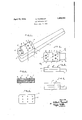
Figure 2 is a plan view with the handle broken away, Figure 3 is a sideview' with the handle broken away, 7 v,
Figure 4 is a sectional View on the line aa of Figure 2 looking in the direction of the arrows,
Figureo is a side view with the handlebroken away showing the tool with the protective cap in place, and
Figure 6 is a bottom view of the protective cap, showing holes adapted to receive and protect the serrating steel points.
A base 1 of soft wood and of about thesame I size as the heel of a mans shoe has connected therewith a wooden handle 2. In use a right-handed man grasps the handle 2 in his right hand and then when needed puts his palm of his left hand onthe back of base 1 to quicken the action of the serrating points.
A second part 3 is cut from hard wood of the same size as base 1 and wood screws; are adapted to secure the parts 1 and 3 firmly together. nine holes are tapped in the piece 3, each adapted to receive one of the steel pins, 5,,5,
- 6, 6, 7, 7, 8, 9 and 10. The pins have the same general form being cylindrical in the Before the union is made however I lower portion fitting in the holes in piece 3 7 but are of different length so that the points lie a curved surfacesymmetrical with the surface of an automobile tire that has been worn smooth Moreover as seenin Figure?) steel pins, 5, 6, and 7 in the two outer rows and steel pins 8, 9, and 10 from front to rear decrease in heightso that they conform with the normal manual handling of an instrument controlled .by a handle in a straightaway pull or push. V drawn throughthe points of steel pins 5, 6 and 7 in either ofthe outer rows or through v the points of steel pins 8, 9, and 10 the line forms a concave curve which'is substantially the same curve as that across the surface of a worn tire, thereby securing uniform action of the steel pins in their objective action of serrating the surface of the worn tire with suction grooves to prevent the worn tire from skidding on the pavement. Similarly if lines be drawn through the points of steel pins 5, 8, 5 and 6, 9, 6, and 7, 10, 7 convex curves are formed having the object of conforming with the curvature of the tire so that the serrations are uniform.
The steel points are hard and tough and as shown are in the form of cones to produce the greatest strength and durability and also to produce a V-shaped serration series in the surface of the tire. It is also self-evident that the construction affords a backing for the ends of the pins, that is pressure sends them against the upper surface of the base 1 and this surface prevents the steel pins and the points from moving out of the predetermined arrangement of their points in fixed position. That is, if the screws 4 are firmly set the back 1 holds the pins securely against inward movement in the tapped holes of the hard-wood supporting piece 3.
Referring now to Figures 5 and 6 when not in use the steel pin points are protected by a soft-wood cap portion 11 which has holes 12 corresponding in size to the steel pins 5, etc. This cap enables the tool to be packed away in the side compartments among steel tools without risk of having the points bent or blunted or otherwise injured. The steel pins in the soft-wood holes are held securely so that the cap 11 remains in protective position but may be quickly removed to use the tool.
A new automobile tire is provided with ridges and conformations having as an objective riding comfort and security against unanticipated slipping on the pavement. It is obvious that as these ridges and protuberances are worn by use the object of preventing skidding or slipping is automatically defeated. Moreover the life of a tire before being ready for discard is much greater than the life of the ridges or protuberances as effective preventers of skidding or slipping. The automobile user is on the horns of the proverbial dilemma; namely he must either lose a large part of his initial tire investment or he must ride on these tires at increased risk of slipping or skidding. The proportion of accidents due to automobile skidding are a vast proportion of the total as I may more or less authoritatively state from my years of eX- perience as a chauffeur. A tool therefore that enables the automobile owner to utilize all of his tire investment and at the same time renews the ridges and protuberances to form effective suction surfaces against skidding not alone meets a long-felt want but is also a great economic boom to the automobile industry and to the safety and security of the automobile passengers.
Now that I have conceived this invention and have disclosed an embodiment of it other modifications will occur to those skilled in the art and I do not choose to limit myself except as in the appended claims.
I claim:
1. A tool for serrating the surface of an automobile tire, comprising in combination a supporting base and a plurality of sharp conical steel pins mounted thereon and adapted to produce grooves in the surface of a tire that has been Worn smooth by drawing said pins across the surface of the worn tire with pressure, said pins being of different length such that a line drawn through three pins in a row at the points forms a concave curve of substantially the same curvature as the transverse curve over the surface of a worn automobile tire.
2. A tool for serrating the surface of an automobile tire to prevent skidding, comprising in combination a supporting base, said supporting base being cut from hard wood and having a plurality of holes therein, a plurality of.sharp conically pointed pins in said holes and projecting from the surface of said base to different lengths such that lines through the points of said pins define a surface similar to that of a worn tire, a cap of soft wood secured to said base and having recesses adapted to cover the heads of said pins and secure them in the projected positions, and a handle adapted to operate said tool.
Signed at New York, in the county of New York and State of New York, this twentyseventh day of August, A. D. 1930.
ALBERT PERRENOT.
Priority Applications (1)
| Application Number | Priority Date | Filing Date | Title |
|---|---|---|---|
| US479507A US1854312A (en) | 1930-09-03 | 1930-09-03 | Tire grooving tool |
Applications Claiming Priority (1)
| Application Number | Priority Date | Filing Date | Title |
|---|---|---|---|
| US479507A US1854312A (en) | 1930-09-03 | 1930-09-03 | Tire grooving tool |
Publications (1)
| Publication Number | Publication Date |
|---|---|
| US1854312A true US1854312A (en) | 1932-04-19 |
Family
ID=23904311
Family Applications (1)
| Application Number | Title | Priority Date | Filing Date |
|---|---|---|---|
| US479507A Expired - Lifetime US1854312A (en) | 1930-09-03 | 1930-09-03 | Tire grooving tool |
Country Status (1)
| Country | Link |
|---|---|
| US (1) | US1854312A (en) |
Cited By (3)
| Publication number | Priority date | Publication date | Assignee | Title |
|---|---|---|---|---|
| US2664630A (en) * | 1951-01-12 | 1954-01-05 | Lawson Grace | Culinary device |
| US2960127A (en) * | 1952-06-25 | 1960-11-15 | Zimmermann Gottfried | Wood ripping device |
| US20130213205A1 (en) * | 2011-08-26 | 2013-08-22 | Daniel Lee Johnson | Device for making lacerations in a surface and method thereof |
-
1930
- 1930-09-03 US US479507A patent/US1854312A/en not_active Expired - Lifetime
Cited By (4)
| Publication number | Priority date | Publication date | Assignee | Title |
|---|---|---|---|---|
| US2664630A (en) * | 1951-01-12 | 1954-01-05 | Lawson Grace | Culinary device |
| US2960127A (en) * | 1952-06-25 | 1960-11-15 | Zimmermann Gottfried | Wood ripping device |
| US20130213205A1 (en) * | 2011-08-26 | 2013-08-22 | Daniel Lee Johnson | Device for making lacerations in a surface and method thereof |
| US9162364B2 (en) * | 2011-08-26 | 2015-10-20 | Daniel Lee Johnson | Device for making lacerations in a surface and method thereof |
Similar Documents
| Publication | Publication Date | Title |
|---|---|---|
| US3266081A (en) | Handle for knives and the like | |
| US1854312A (en) | Tire grooving tool | |
| US3103242A (en) | Supplemental traction device | |
| US2308251A (en) | Toe guard and brake for skating shoes | |
| US2368200A (en) | Protecting pad for automobile fenders | |
| US436993A (en) | Cycle-wheel | |
| US1771319A (en) | Vehicle bumper | |
| US791343A (en) | Sleigh-runner for wheeled vehicles. | |
| US2181779A (en) | Skate guard | |
| US2633888A (en) | Skid chain | |
| US863535A (en) | Rubber-tire protector. | |
| US1129075A (en) | Ice-skate. | |
| US1590533A (en) | Resilient tire | |
| US503846A (en) | Detachable tire | |
| US2090696A (en) | Tractor lug | |
| US1460183A (en) | Roller for skates | |
| CN217648420U (en) | Balanced lead double-purpose sword | |
| US4291077A (en) | Method and apparatus for installing a wheel cover | |
| US1417584A (en) | Mandrel for abrasive and polishing tools | |
| US1824525A (en) | Traction device | |
| RU2093368C1 (en) | Antiskid pin | |
| US1041768A (en) | Tool for dressing emery-wheels. | |
| US508707A (en) | Racing-sulky | |
| US1202726A (en) | Tire-protector. | |
| US1314462A (en) | Wheel |