US1854046A - Apparatus for manufacturing concrete pipes - Google Patents
Apparatus for manufacturing concrete pipes Download PDFInfo
- Publication number
- US1854046A US1854046A US401227A US40122729A US1854046A US 1854046 A US1854046 A US 1854046A US 401227 A US401227 A US 401227A US 40122729 A US40122729 A US 40122729A US 1854046 A US1854046 A US 1854046A
- Authority
- US
- United States
- Prior art keywords
- mould
- shaft
- supported
- pipes
- frame
- Prior art date
- Legal status (The legal status is an assumption and is not a legal conclusion. Google has not performed a legal analysis and makes no representation as to the accuracy of the status listed.)
- Expired - Lifetime
Links
- 239000004567 concrete Substances 0.000 title description 17
- 238000004519 manufacturing process Methods 0.000 title description 7
- 238000003825 pressing Methods 0.000 description 9
- 239000000463 material Substances 0.000 description 7
- 238000009499 grossing Methods 0.000 description 4
- 238000000465 moulding Methods 0.000 description 4
- IHPYMWDTONKSCO-UHFFFAOYSA-N 2,2'-piperazine-1,4-diylbisethanesulfonic acid Chemical compound OS(=O)(=O)CCN1CCN(CCS(O)(=O)=O)CC1 IHPYMWDTONKSCO-UHFFFAOYSA-N 0.000 description 3
- 239000007990 PIPES buffer Substances 0.000 description 3
- XLYOFNOQVPJJNP-UHFFFAOYSA-N water Substances O XLYOFNOQVPJJNP-UHFFFAOYSA-N 0.000 description 3
- XEEYBQQBJWHFJM-UHFFFAOYSA-N Iron Chemical compound [Fe] XEEYBQQBJWHFJM-UHFFFAOYSA-N 0.000 description 2
- 238000010276 construction Methods 0.000 description 2
- 230000007547 defect Effects 0.000 description 2
- 241001315609 Pittosporum crassifolium Species 0.000 description 1
- 239000011230 binding agent Substances 0.000 description 1
- 150000001768 cations Chemical class 0.000 description 1
- GLWWLNJJJCTFMZ-UHFFFAOYSA-N cyclanilide Chemical compound C=1C=C(Cl)C=C(Cl)C=1NC(=O)C1(C(=O)O)CC1 GLWWLNJJJCTFMZ-UHFFFAOYSA-N 0.000 description 1
- 238000007730 finishing process Methods 0.000 description 1
- 229910052742 iron Inorganic materials 0.000 description 1
- 230000001105 regulatory effect Effects 0.000 description 1
- 239000011150 reinforced concrete Substances 0.000 description 1
- 230000002441 reversible effect Effects 0.000 description 1
- 238000007790 scraping Methods 0.000 description 1
- 239000000725 suspension Substances 0.000 description 1
Images

Classifications
-
- B—PERFORMING OPERATIONS; TRANSPORTING
- B28—WORKING CEMENT, CLAY, OR STONE
- B28B—SHAPING CLAY OR OTHER CERAMIC COMPOSITIONS; SHAPING SLAG; SHAPING MIXTURES CONTAINING CEMENTITIOUS MATERIAL, e.g. PLASTER
- B28B21/00—Methods or machines specially adapted for the production of tubular articles
- B28B21/02—Methods or machines specially adapted for the production of tubular articles by casting into moulds
- B28B21/10—Methods or machines specially adapted for the production of tubular articles by casting into moulds using compacting means
- B28B21/22—Methods or machines specially adapted for the production of tubular articles by casting into moulds using compacting means using rotatable mould or core parts
- B28B21/24—Methods or machines specially adapted for the production of tubular articles by casting into moulds using compacting means using rotatable mould or core parts using compacting heads, rollers, or the like
- B28B21/245—Methods or machines specially adapted for the production of tubular articles by casting into moulds using compacting means using rotatable mould or core parts using compacting heads, rollers, or the like using a horizontal compacting roller in a horizontally rotatable mould
Definitions
- This invention relates to improvements in apparatus for manufacturing concrete pipes and particularly to such an apparatus employing a centrifugal mould supported between two supporting plates and includingv a smoothing and compacting mechanism movable into said mould for compacting and smoothing the inner surface of the pipes.
- finishing processes from crude, to the last fin ish by utilizing the'centrifugal force of the revolutions of the mould, secondly, to enhance the strength of the pipes coming out of the mould by giving a strong pressureto the end-part near the mouth of such a pipe, and lastly, to produce quickly concrete pipes of high, uniform and accurate qualities.
- the returns are found isolated due to the fact that the centrifugal force utilized is not distributed even- 1y along pipes so that the concrete cast, collects and sets unevenly, with the consequence that the inner wall of pipes presentsa rough and uneven surface and the desired uniformity of thickness and of density are not obtained.
- the present apparatus has been devised by which concrete cast into the mould is given almost an equal pressure against its entire inner wall, and after belng roughly finished by the scraper the last finish is given to the cast pipe so that uniform thlckness with a smooth surface can be obtained.
- the device is of such a construction the whole length of'the inside of" that it requires no particular-skill fora working man to handle it.
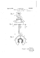
- Fig. 1 is a side elevation of the apparatus, partly in section to. show the internal construction thereof
- Fig. 2 is a top plan view of the same
- Fig. 3 is an end view
- Fig. 4 is a sectional view taken along the line IV and IV of the Fig.
- Fig. 5 is a section taken on the line VV of Fig. 1
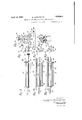
- Fig. 6 is vertical sectional View of the frame of a splash-guard
- F ig.r7 is a hand view thereof
- Fig. 8 the'pressing device
- Fig. 9 is a sectional View taken on the line IX and IX of Fig. 8
- Fig.10 is a side elevation ofa modified form of the said pressing 66 device
- Fig. 11 is a sectional viewtof the modified device taken on the line XI and XI of the Fig. 10
- Fig. 12 is a side elevation of another modifi'cation of the pressing, device
- v and Fig. 13 shows the section of Fig. 12 taken on the line XIII and XIII thereof.
- a pair of bearing blocks (3) and (4) the upper parts of which are 4 formed as bearings and
- a hollow shaft (7 to which is fitted a brake-wheel (8) is supported by the said bearings and has pulleys (9) and (10) connected there- U with at certain p'ointsbetween the bearings.
- the hollow shaft (7) carries a brake-wheel (8) at its outer end, and, also carries a mould supporting plate (11) which is fixed onits inner end and which supports one end of the v mould. To the right of the said plate, a 3
- the lower part of the bar has a bifurcated portion which supports the upper roller (21), which together with the lower supporting rollers (14) and (15) su tains the mould supporting plate (22).
- the mould (23) Between the mould supporting plates (11) and (22) is inserted the mould (23), which has formed adj acent the end thereof flanges (24) and (25) provided with binding-screws (26) and (27) which are loosely fitted through the holes (28) and (29) in the mould supporting plates and are provided with threaded securing nuts 30 and 31 to rigidly fix the mould to the supporting plates.
- a slideframe is mounted horizontally on the blocks (16), (32), (33), and (34) at the right-hand side of the abovementioned foundation block (12) so that a saddle shaped frame can be moved right and left upon the said slider by means of turning the handle (37
- the saddle-shaped frame (36) consists of a pair of spaced upstanding frames (38) and (40) which mount the open mouthed sleeve pipe (41) embracing the right-hand end of the horizontal shaft (42) of the scraping device.
- the upper end of the frames 38 and 40 are split and are provided with binding screws 43 and 44.
- the binders (43) and (44) are tightened and the mouth of the said sleeve-pipe is closed tightly by which means the horizontal shaft 42 is supported on level.
- a revolving shaft (45) is provided, and has one end supported by the said frames 38 and 40.
- a small toothed-wheel (46) is fixed to the righthand end of shaft 45 and engages with a worm-gear (47) the spindle (49) of which protrudes outwardly and has a handle (48) fitted thereto, by turning of which the revolving shaft rotates.
- Two hangers (50) and (51) at a distance of nearly the whole length of the mould, support the revolving shaft from the shaft 42 in a horizontal line.
- the said shaft is provided with the outer-pressing roller (52) and scraper (53) whichare fixed thereto.
- a bearing shaft '56 extending from the hanger 50 into the hollow shaft '4' serves to support and steady the left end of the horizontal shaft 42.
- the splash-guarding frame (67 is so dis posed as to cover the left-side mouth of the mould above mentioned and its head is hinged to the bar (57) which extends to the left of the mould and is supported by the supporting uprights (58) and (59) erected on the blocks (3) and
- the said guarding frame has hooks (60) and (61) on either hinged half to which a drawing cord (62) is tied on one end, and on the other, to the saddle-sha 'md frame (36) through suitable pulleys, so that when the saddle-frame is moved to the right, the splash-guard frame is auton'iatically opened by action of the cord.
- the frameblocks (13) of the lower supporting-rollers (14) and (15) are positioned between upstanding flanges (63) and (64) which stand fixed to the block (12) and by manipulating the pushing screws (65) and (66) which are threaded through said flanges the position of the frame-blocks (13) maybe regulated.
- One end of the scraper (53) of the outer pressing device shown in Fi s. 8 and 9 is formed with projection (68) at one end and a large finishing roller (70) of Various sizes adaptable to the sockets, is carried at the opposite end of the pressing roller. 52).
- Figs. 12 and 13 show the brush-scraper (55) by which the smoothing operation of the inner face is brought to the finish.
- the mould is first fixed between the mould supporting plates (11) and (12) after which the oulley (,3 is set to motion by means of a belt stretched between the said pulley and another pulley fixed to a driving shaft (the latter pulley andthe sha t not shown in the drawings), when the material is thrown into the mould from the right hand side of its mouth.
- the centrifugal force developed by the rotation of the mould forces the material outward to the inner surface of the mould.
- the revolving shaf (45) is made to rotate through the worm-gear (47) and small toothed wheel and by means of the scraper (53) attached to the said shaft, the inner face of the moulded pipe is smoothed and brought to arough finish.
- the next operation is to so turn the revolving shaft so as to bring under it the outer-pressing roll (52), which by pressing the semifinished inner face of the molded pipe and at the same time sufficiently poundingthe material completes the condensing and smoothing of the inner face; the refuse or excess material being discharged from the left-hand end of the mould into the splashguarding frame (67) through a space into mould-supporting plate (11).
- the reinforced concrete pipes can be made in the same manner by preparing and introducing iron bars into the mould before the commencement of moulding operations.
- the handle (3'?) is turned which moves the saddle shaped frame (36) to the right hand end of the slide frame- (35), when the mould (23) is taken off.
- a new mould is then fitted to the mould supporting plates (11) and (12) and the saddle shaped frame is moved towards the left side.
- the bar (56) fixed to the hanger (50) is in sorted into the hollow shaft (7).
- the mouth of the splash-guarding frame opens when the said saddle shaped frame moves towards rightand closes when it goes to the opposite direction thus forming a splash-guarding chamber.
- the relative position of the lower rollers to the mould is made adjustable by adjusting the pushing screws and (66) against the frame blocks (13), and that of the upper roller, by raising or lowering of the threaded bar (19) by means of the handle Wheel (18).
- revolutions of the mould is not limitedto one direction only but is made reversible by which means the density of concrete may be enhanced, and further that a speed-regulating device may be attached to the device by which the revolutions of mould may, instead of. being kept uniform, be altered according to requirements.
- an open ended centrifugal mould a sliding carriage mounted adjacent one end thereof, a supporting shaft carried by said carnage and adapted to extend into said mould, apair of hangers carried by said shaft, a rotatable shaft journalled in said hangers and a finishing element carried by said rotatable shaft.
- an open ended centrifugal mould a sliding carriage mounted adjacent one end thereof, a supporting shaft carried by said carriage and adapted to extend into said mould, a pair of hangers carried by said shaft, a ro tatable shaft journalled in said hangers, a
- finishing element carriedby said rotatableshaft, and means for rotating said rotatable shaft whereby to adjust the position of said finishing element with respect to the walls of said mould.
- a pair of mould supporting plates having a central opening therein and adapted to engage the ends of a tubular centrifugal mould, a horizontally supported rotatable hollow shaft, means. for mounting one of said plates on one end of said shaft, means for rotatably supporting the other'of said plates so as to dispose said mould in a horizontal position, a reciprocal carriage mounted adjacent one end of said mould, a horizontal shaft supported by and extending forwardly of said carriage and adapted to extend into said mould, a bearing portion formed at the forward end of said shaft and adapted to fit within the open end of said hollow shaft,
- a pair of mould supporting plates having a central opening therein, and adapted to engage the ends of a tubular centrifugal mould
- a horizontally supported rotatable hollow shaft means for mounting one of said plates on one end of said shaft, means for rotatably supporting the other of said plates so as to dispose said mould in a horizontal position, a reciprocal carriage mounted adjacent one end ofsaid mould, a horizontal shaft supported by and extending forwardly of said carriage and adapted to extend into said mould, a bearing portion formed at the forward end of said shaft and adapted to fit within the open end of said hollow shaft, a pair of hangers carried by said shaft, a rotatable shaft journalled in said hangers, and a finishing element carried by said rotatable shaft, and means for rotating said rotatable shaft whereby to adjust the position of said finishing element with respect to the sidesof the mould;
- an elongated scraper blade supported in alinement with the side of said mould and having a laterally projecting portion at one end for forming the pipe socket, an elongated finishing roller supported in alinement with the side of said mould and a radially enlarged finishing roller caradjustably mounting said scraper blade and finishing rollers within said mould whereby to successively bring them into operative relation with the material being moulded.
- An apparatus for centrifugally moulding concrete pipe an elongated scraper blade supported in alinement with the side of said mould, an elongated finishing roller supported in alinement with the side of said mould, and a pair of end finishing rollers supported one adjacent each end of said mould whereby to compress the concrete adjacent the ends of said mould and means for adjustably mounting said blade, finishing roller and end finishing rollers whereby to selectively position them in operative relation with the material being moulded.
Landscapes
- Engineering & Computer Science (AREA)
- Manufacturing & Machinery (AREA)
- Chemical & Material Sciences (AREA)
- Ceramic Engineering (AREA)
- Mechanical Engineering (AREA)
- Manufacturing Of Tubular Articles Or Embedded Moulded Articles (AREA)
Description
April 12, 1932. s. KUROYANAGI 1,854,046
APPARATUS FOR MANUFACTURING CONCRETE PIPES Filed Oct. 21 1929 3 Sheets- Sheet 1 Q q A? a L Q g/ N N, "a w c M/ CB "n n INVENTOR SWQL ZJ'O sgfuroyana yz/ ATTORNEYS April 1932- s. KUROYANAGI 1,854,046
APPARATUS FOR MANUFACTURING CONCRETE PIPES Filed Oct. 21, 1929 3 Sheets-Sheet 2 INVENTOR ,S'u a zlro Karo *an i/ y] M y a ATTORNEYS April 12, 1932. s. KUROYANAGI APPARATUS FOR MANUFACTURING CONCRETE PIPES Filed Oct. 21, 1929 3 SheetsSheet I NVEN TOR a iro liw'ayana v ATTORNEYS Patented Apr. 12, 1932 SUGAJIRO KUR-OYANAGI, 'OF KI'IASANJO, SAPPOBO, JAPAN APPARATUS FOR- MANUFACTURING CONCRETE PIIEES Application filed October 21, 1929. Serial No. 401,227.
This invention relates to improvements in apparatus for manufacturing concrete pipes and particularly to such an apparatus employing a centrifugal mould supported between two supporting plates and includingv a smoothing and compacting mechanism movable into said mould for compacting and smoothing the inner surface of the pipes.
The objects of the present invention are '10 firstly, to complete, within the mould, the
finishing processes, from crude, to the last fin ish by utilizing the'centrifugal force of the revolutions of the mould, secondly, to enhance the strength of the pipes coming out of the mould by giving a strong pressureto the end-part near the mouth of such a pipe, and lastly, to produce quickly concrete pipes of high, uniform and accurate qualities.
In the hitherto known apparatuses'for concrete pipe manufacture, the utilization of centrifugal force is not unknown but the means of its application is of such a simple nature that with the proportion of water recognized as suitable for a good concrete, the material is found too hard to adhere sufliciently and solidly to the inner wall of the mould which makes unavoidable in general practice the use of more water than. the recognized proportion resulting in excess water oozing out during' the work so that such excess 1s often pumped out of the mould causlng a temporary suspension of work. Consequently 1n the finished concrete pipes, the returns are found isolated due to the fact that the centrifugal force utilized is not distributed even- 1y along pipes so that the concrete cast, collects and sets unevenly, with the consequence that the inner wall of pipes presentsa rough and uneven surface and the desired uniformity of thickness and of density are not obtained. To remedy the above defects and to increase the strength of pipes the present apparatus has been devised by which concrete cast into the mould is given almost an equal pressure against its entire inner wall, and after belng roughly finished by the scraper the last finish is given to the cast pipe so that uniform thlckness with a smooth surface can be obtained. Besides, the device is of such a construction the whole length of'the inside of" that it requires no particular-skill fora working man to handle it.
In the annexed drawings, Fig. 1 is a side elevation of the apparatus, partly in section to. show the internal construction thereof, Fig. 2 is a top plan view of the same, Fig. 3 is an end view, Fig. 4 is a sectional view taken along the line IV and IV of the Fig.
1, Fig. 5 is a section taken on the line VV of Fig. 1, Fig. 6 is vertical sectional View of the frame of a splash-guard, F ig.r7 is a hand view thereof, Fig. 8 the'pressing device, Fig. 9 is a sectional View taken on the line IX and IX of Fig. 8, Fig.10 is a side elevation ofa modified form of the said pressing 66 device, Fig. 11 is a sectional viewtof the modified device taken on the line XI and XI of the Fig. 10, Fig. 12 is a side elevation of another modifi'cation of the pressing, device, v and Fig. 13 shows the section of Fig. 12 taken on the line XIII and XIII thereof.
To describe the apparatus in detail by the drawings, upon the foundation-blocks (1) and (2) are fixed a pair of bearing blocks (3) and (4) the upper parts of which are 4 formed as bearings and A hollow shaft (7 to which is fitted a brake-wheel (8) is supported by the said bearings and has pulleys (9) and (10) connected there- U with at certain p'ointsbetween the bearings. The hollow shaft (7) carries a brake-wheel (8) at its outer end, and, also carries a mould supporting plate (11) which is fixed onits inner end and which supports one end of the v mould. To the right of the said plate, a 3
pair of frame-blocks (13) and (13) are fixed on the foundation-block (12). The blocks 13 support two lower supporting rollers (let) and (15) respectively positioned opposite to each other. Upon" the foundationblock (16) which is close to the block (12) is erected a column (39) onto the upper part of which an arm (17 is fitted in such a manner that it can be freely moved horizontal- 95 ly. The end of'the said arm has a vertical screw threaded bar (19) which extends through the threaded hub of thehand wheel 18 carried by said arm so that by turning of the hand wheel (18), the said bar rises .100
and falls. The lower part of the bar has a bifurcated portion which supports the upper roller (21), which together with the lower supporting rollers (14) and (15) su tains the mould supporting plate (22). Between the mould supporting plates (11) and (22) is inserted the mould (23), which has formed adj acent the end thereof flanges (24) and (25) provided with binding-screws (26) and (27) which are loosely fitted through the holes (28) and (29) in the mould supporting plates and are provided with threaded securing nuts 30 and 31 to rigidly fix the mould to the supporting plates. A slideframe is mounted horizontally on the blocks (16), (32), (33), and (34) at the right-hand side of the abovementioned foundation block (12) so that a saddle shaped frame can be moved right and left upon the said slider by means of turning the handle (37 The saddle-shaped frame (36), consists of a pair of spaced upstanding frames (38) and (40) which mount the open mouthed sleeve pipe (41) embracing the right-hand end of the horizontal shaft (42) of the scraping device. The upper end of the frames 38 and 40 are split and are provided with binding screws 43 and 44. The binders (43) and (44) are tightened and the mouth of the said sleeve-pipe is closed tightly by which means the horizontal shaft 42 is supported on level. At a certain distano-e under the said horizontal shaft a revolving shaft (45) is provided, and has one end supported by the said frames 38 and 40. A small toothed-wheel (46) is fixed to the righthand end of shaft 45 and engages with a worm-gear (47) the spindle (49) of which protrudes outwardly and has a handle (48) fitted thereto, by turning of which the revolving shaft rotates. Two hangers (50) and (51), at a distance of nearly the whole length of the mould, support the revolving shaft from the shaft 42 in a horizontal line. The said shaft is provided with the outer-pressing roller (52) and scraper (53) whichare fixed thereto. A bearing shaft '56 extending from the hanger 50 into the hollow shaft '4' serves to support and steady the left end of the horizontal shaft 42.
The splash-guarding frame (67 is so dis posed as to cover the left-side mouth of the mould above mentioned and its head is hinged to the bar (57) which extends to the left of the mould and is supported by the supporting uprights (58) and (59) erected on the blocks (3) and The said guarding frame has hooks (60) and (61) on either hinged half to which a drawing cord (62) is tied on one end, and on the other, to the saddle-sha 'md frame (36) through suitable pulleys, so that when the saddle-frame is moved to the right, the splash-guard frame is auton'iatically opened by action of the cord. The frameblocks (13) of the lower supporting-rollers (14) and (15) are positioned between upstanding flanges (63) and (64) which stand fixed to the block (12) and by manipulating the pushing screws (65) and (66) which are threaded through said flanges the position of the frame-blocks (13) maybe regulated. One end of the scraper (53) of the outer pressing device shown in Fi s. 8 and 9 is formed with projection (68) at one end and a large finishing roller (70) of Various sizes adaptable to the sockets, is carried at the opposite end of the pressing roller. 52). As for the concrete pipes provided with no sockets, they tend to break down after being moulded so that to remedy this defect, the edge pressing rollers and (69) are provided at both ends of the supplementary roller (54) and by this means the mouth-end parts of pipes are strongly pressed before their inner faces are levelled by the scraper (53) to a semifinishcd condition. Figs. 12 and 13 show the brush-scraper (55) by which the smoothing operation of the inner face is brought to the finish.
To describe the operation, the mould is first fixed between the mould supporting plates (11) and (12) after which the oulley (,3 is set to motion by means of a belt stretched between the said pulley and another pulley fixed to a driving shaft (the latter pulley andthe sha t not shown in the drawings), when the material is thrown into the mould from the right hand side of its mouth. The centrifugal force developed by the rotation of the mould, forces the material outward to the inner surface of the mould. Then by turning the handle (48), the revolving shaf (45) is made to rotate through the worm-gear (47) and small toothed wheel and by means of the scraper (53) attached to the said shaft, the inner face of the moulded pipe is smoothed and brought to arough finish. The next operation is to so turn the revolving shaft so as to bring under it the outer-pressing roll (52), which by pressing the semifinished inner face of the molded pipe and at the same time sufficiently poundingthe material completes the condensing and smoothing of the inner face; the refuse or excess material being discharged from the left-hand end of the mould into the splashguarding frame (67) through a space into mould-supporting plate (11). It is to be remarked in this connection that the reinforced concrete pipes can be made in the same manner by preparing and introducing iron bars into the mould before the commencement of moulding operations. When the moulding of a pipe is thus finished, the handle (3'?) is turned which moves the saddle shaped frame (36) to the right hand end of the slide frame- (35), when the mould (23) is taken off. A new mould is then fitted to the mould supporting plates (11) and (12) and the saddle shaped frame is moved towards the left side.
The bar (56) fixed to the hanger (50) is in sorted into the hollow shaft (7). Thus arranged, the operation above described is re peated. The mouth of the splash-guarding frame opens when the said saddle shaped frame moves towards rightand closes when it goes to the opposite direction thus forming a splash-guarding chamber. To meet the.
changes in axial centre of a mould which is supported by the lower and upper supporting rollers (l4), (l5) and (21) due to the sizes .of moulds required, the relative position of the lower rollers to the mould is made adjustable by adjusting the pushing screws and (66) against the frame blocks (13), and that of the upper roller, by raising or lowering of the threaded bar (19) by means of the handle Wheel (18).
It is to be noted that the revolutions of the mould is not limitedto one direction only but is made reversible by which means the density of concrete may be enhanced, and further that a speed-regulating device may be attached to the device by which the revolutions of mould may, instead of. being kept uniform, be altered according to requirements.
Claims:
1. In a device of the character described,
an open ended centrifugal mould, a sliding carriage mounted adjacent one end thereof, a supporting shaft carried by said carnage and adapted to extend into said mould, apair of hangers carried by said shaft, a rotatable shaft journalled in said hangers and a finishing element carried by said rotatable shaft.
2. In a device of the character described, an open ended centrifugal mould, a sliding carriage mounted adjacent one end thereof, a supporting shaft carried by said carriage and adapted to extend into said mould, a pair of hangers carried by said shaft, a ro tatable shaft journalled in said hangers, a
finishing element carriedby said rotatableshaft, and means for rotating said rotatable shaft whereby to adjust the position of said finishing element with respect to the walls of said mould.
3. In a device of the character described, a pair of mould supporting plates having a central opening therein and adapted to engage the ends of a tubular centrifugal mould, a horizontally supported rotatable hollow shaft, means. for mounting one of said plates on one end of said shaft, means for rotatably supporting the other'of said plates so as to dispose said mould in a horizontal position, a reciprocal carriage mounted adjacent one end of said mould, a horizontal shaft supported by and extending forwardly of said carriage and adapted to extend into said mould, a bearing portion formed at the forward end of said shaft and adapted to fit within the open end of said hollow shaft,
and a finishing element supportedby said shaft.- i
r 4. In a devic-e of the character described,
said carriage and adapted to extend into said mould, bearing portionformed at the for ward end of said shaft and adapted to fit within the open end of said hollow shaft, a pair of hangers carried by said shaft, a rotatable shaft journalled in said hangers, and a finishing element carried by said rotatable shaft. i
5. In a device of the character described, a pair of mould supporting plates having a central opening therein, and adapted to engage the ends of a tubular centrifugal mould,
' a horizontally supported rotatable hollow shaft, means for mounting one of said plates on one end of said shaft, means for rotatably supporting the other of said plates so as to dispose said mould in a horizontal position, a reciprocal carriage mounted adjacent one end ofsaid mould, a horizontal shaft supported by and extending forwardly of said carriage and adapted to extend into said mould, a bearing portion formed at the forward end of said shaft and adapted to fit within the open end of said hollow shaft, a pair of hangers carried by said shaft, a rotatable shaft journalled in said hangers, and a finishing element carried by said rotatable shaft, and means for rotating said rotatable shaft whereby to adjust the position of said finishing element with respect to the sidesof the mould; I
6. In an apparatus for centrifugally moulding concrete pipe, an elongated scraper blade supported in alinement with the side of said mould and having a laterally projecting portion at one end for forming the pipe socket, an elongated finishing roller supported in alinement with the side of said mould and a radially enlarged finishing roller caradjustably mounting said scraper blade and finishing rollers within said mould whereby to successively bring them into operative relation with the material being moulded.
8. An apparatus for centrifugally moulding concrete pipe, an elongated scraper blade supported in alinement with the side of said mould, an elongated finishing roller supported in alinement with the side of said mould, and a pair of end finishing rollers supported one adjacent each end of said mould whereby to compress the concrete adjacent the ends of said mould and means for adjustably mounting said blade, finishing roller and end finishing rollers whereby to selectively position them in operative relation with the material being moulded.
In testimony whereof I have signed my name to this specification.
SUGAJIRO KUROYANAGI.
Priority Applications (1)
| Application Number | Priority Date | Filing Date | Title |
|---|---|---|---|
| US401227A US1854046A (en) | 1929-10-15 | 1929-10-21 | Apparatus for manufacturing concrete pipes |
Applications Claiming Priority (2)
| Application Number | Priority Date | Filing Date | Title |
|---|---|---|---|
| GB3134129A GB341122A (en) | 1929-10-15 | 1929-10-15 | Improvements in apparatus for the centrifugal casting of concrete pipes |
| US401227A US1854046A (en) | 1929-10-15 | 1929-10-21 | Apparatus for manufacturing concrete pipes |
Publications (1)
| Publication Number | Publication Date |
|---|---|
| US1854046A true US1854046A (en) | 1932-04-12 |
Family
ID=26260857
Family Applications (1)
| Application Number | Title | Priority Date | Filing Date |
|---|---|---|---|
| US401227A Expired - Lifetime US1854046A (en) | 1929-10-15 | 1929-10-21 | Apparatus for manufacturing concrete pipes |
Country Status (1)
| Country | Link |
|---|---|
| US (1) | US1854046A (en) |
-
1929
- 1929-10-21 US US401227A patent/US1854046A/en not_active Expired - Lifetime
Similar Documents
| Publication | Publication Date | Title |
|---|---|---|
| US1854046A (en) | Apparatus for manufacturing concrete pipes | |
| US2148558A (en) | Method and apparatus for coating cylinders | |
| US2446476A (en) | Apparatus for coating cylindrical surfaces | |
| US1993930A (en) | Mold for building constructional elements of concrete | |
| US1750748A (en) | Method and apparatus for making articles from alpha plastic substance | |
| CN219851822U (en) | Bending machine for iron wire production | |
| US2149029A (en) | Mechanism for making composition shingles | |
| CN212583154U (en) | Building ground decorates laying device | |
| US1863839A (en) | Machine for manufacturing hollow concrete bricks | |
| US2750646A (en) | Ceramic column texturing machines | |
| US106424A (en) | Improved water-pipe machine | |
| US2133517A (en) | Coating apparatus | |
| US3738A (en) | Machine formaking- sand | |
| NO116976B (en) | ||
| SU576219A1 (en) | Plant for applying protective layer onto core of centrifugally moulded tube | |
| US1479149A (en) | Apparatus for the manufacture of weldless tubes from fibrous materials and hydraulic cement substances | |
| US1380598A (en) | Machine for forming concrete blocks | |
| US341163A (en) | Machine for making paper pails | |
| US732421A (en) | Hat-body-felting machine. | |
| US400893A (en) | Sand-molding machine | |
| US1129797A (en) | Pottery-molding machine. | |
| CN216080752U (en) | Drying and dehumidifying device for rice processing | |
| US1303966A (en) | Machine fob | |
| CN221988601U (en) | A leather processing drying machine | |
| CN108890470A (en) | A kind of plastic mould surface processing device |