US1853928A - Belt fastener applying machine - Google Patents
Belt fastener applying machine Download PDFInfo
- Publication number
- US1853928A US1853928A US473833A US47383330A US1853928A US 1853928 A US1853928 A US 1853928A US 473833 A US473833 A US 473833A US 47383330 A US47383330 A US 47383330A US 1853928 A US1853928 A US 1853928A
- Authority
- US
- United States
- Prior art keywords
- prongs
- belt
- rollers
- roller
- fastener means
- Prior art date
- Legal status (The legal status is an assumption and is not a legal conclusion. Google has not performed a legal analysis and makes no representation as to the accuracy of the status listed.)
- Expired - Lifetime
Links
Images
Classifications
-
- F—MECHANICAL ENGINEERING; LIGHTING; HEATING; WEAPONS; BLASTING
- F16—ENGINEERING ELEMENTS AND UNITS; GENERAL MEASURES FOR PRODUCING AND MAINTAINING EFFECTIVE FUNCTIONING OF MACHINES OR INSTALLATIONS; THERMAL INSULATION IN GENERAL
- F16G—BELTS, CABLES, OR ROPES, PREDOMINANTLY USED FOR DRIVING PURPOSES; CHAINS; FITTINGS PREDOMINANTLY USED THEREFOR
- F16G3/00—Belt fastenings, e.g. for conveyor belts
- F16G3/003—Apparatus or tools for joining belts
-
- Y—GENERAL TAGGING OF NEW TECHNOLOGICAL DEVELOPMENTS; GENERAL TAGGING OF CROSS-SECTIONAL TECHNOLOGIES SPANNING OVER SEVERAL SECTIONS OF THE IPC; TECHNICAL SUBJECTS COVERED BY FORMER USPC CROSS-REFERENCE ART COLLECTIONS [XRACs] AND DIGESTS
- Y10—TECHNICAL SUBJECTS COVERED BY FORMER USPC
- Y10T—TECHNICAL SUBJECTS COVERED BY FORMER US CLASSIFICATION
- Y10T29/00—Metal working
- Y10T29/53—Means to assemble or disassemble
- Y10T29/53709—Overedge assembling means
- Y10T29/53713—Belt-hook attacher
Definitions
- nnn'r rns'rnnnnn APPLYING .MnoI-IrNE App ication fil a hi eest 1 Sex 1 9- .31 33- Th s v nti n re es 11 a el i st n f l p plying machines and is inthe natnrenf an imp ov e e t ma in disc se in my prior Patent 1,75%,959 issued.December[24 5; 1929.- 1
- chine is designed primarily tor applying belt lacings, hooks or fastener means toLvi ide belts or aprons, such as commonly used in laundry ironers or the like, although adapted for other similar uses, as Will be understood, by r those skilled in the art.
- the fastener means are inserted inia holder 01' rack and theedge lofthe hel -t inserted within theprongs of the fastener means.
- a carriage having two plane surface rollers set progressively relatiyelylto the fastener means is then moved lengthwise ofthe fastener means at thebelt edge soth'at pressure is progressively applied bythe rollers to imbed in and clinch the fastener means to the belt end.
- Figure 5 is a View similar to ' Figure llbutfillustratingtheda'st pressure roller.
- Figurefi 1 Figure is an enlarged vertical sectional View corresporidlng approxlmatelyf to the line L- ⁇ of Figure '1 ancl'show ng more. pardon;
- beltl hereinafter employed, is usecl n a generic sense to 1nclude not only belts of leather but belts or. apronsof fabric or othenmaterial.
- Mountdpnthegbed plate lO is'a rearrack supporting platell, secured 1n place by suitable bolts 12.
- P e e' is e e h esie "geeepee 'e' 59 a purpose hereinafter specified and on top of the latter is a rack 14, which extends the length of the machine, said rack 14 and plate 13 being secured by a plurality of bolts: 15 at suitable intervals therealong.
- a heavy plate 16 to which is secured an inwardly overhanging guide plate 17, and on the top of the latter is secured the belt fastener means holder 18, said plates 16 and 17 and holder 18 extending the full length of the machine, as will be understood.
- a preferably case hardened anvil plate 19 against which the lacings or fasteners are clinched is inserted in the top face of the plate 17 .
- a horizontal table or support is provided not only for the lacings or fasteners but for the beltfend 20.
- the holder 18 is detachably or removably secured in position by countersunk screws 21 so that different holders may be used with the same apparatus.
- Bodily movable lengthwise of the machine is a carriage, the main casting of which is indicated by the reference character A.
- Said carriage is relatively elongated and is formed with three generally semi-circular housings 22, 23 and 24 along the rear side and also with web sections 2525 providing three sets of bearings for the pinions and pressure rollers, hereinafter described.
- the carriage casting A is further provided with depending web sections 26, with which are cast integrally two journal bearings 27 for the guide rollers hereinafter described. Journaled in the three sets of upper journal bearings are three shafts 28, 29 and 30, respectively.
- the guide rollers 132 engage .under the guide plates 13 and 17, and obviously prevent the carriage A from lif ing up and consequently the-exertion of pressure on the fastener means by the pressure rollers.
- the front guide plate 17 is also preferably provided with a longitudinally extending groove 34 in which works a corresponding guide flange 35 formed on the earriage casting, so as to maintain the true path of longitudinal travel of the carriage in its movements back and forth on the machine.
- each shaft is cut away at its inner end so as to provide a flange section 37 within the hubportion 38 of the pinion.
- Each hub portion 38 carries two set screws 39-39 cooperable with the flange section 37 so that the pinion can be adjusted angularly with respect to the shaft, which in turn provides for the angular adjustment between the pinions and the respective pressure rollers 31 and 32 at the other'ends of the shafts, for the purpose hereinafter described.
- the third shaft 30 carries at its rear end another pinion 40, which may be keyed or pinned as shown in Figure 3 and said shaft 30 also carries an operating handle 41. 'As will be understood, all pinion-s 36 and 40 cooperate with the rack 14 so that, upon rotation of the handle 41, positive movement longitudinally of the machine is imparted to the carriage and all three pressure rollers are simultaneously and positively rotated.
- the front end of its shaft 30 is preferably adjustable vertically in an anti-friction ball bearing 42, by means of a set screw 43, so that the distance between the active plane surface of the roller 33 and the anvil plate 19 can be accurately gauged and adjusted.
- the two advance pressure rollers 31 and 32 are of like construction, each being preferably splined to its corresponding shaft.
- Each of said rollers has its periphery provided with a series of teeth 44-44, which are inclined from upper left downwardly to lower right, as viewed in top'plan and as shown in Figure 1.
- the teeth on the underside of said pressure rollers where the same engage with the prongs 45 ofthe fastener means, as shown best in Figures 4 and 6, will have the teeth all sloping in the opposite direction.
- Said teeth 44 are of a pitch or are so spaced as to correspond accurately with the spacing of the prongs 45 of the fastener means, whether the latter be of the continuous belt lacing type or the individual hook type.
- the angular adjustment provided for between the pressure rollers 31 and 32 and their respective pinions 36 permits of the accurateadjustment of the teeth 44, with the notches 46 of the holder 18 that carries and positions the fastener means 45, the latter being held in place by a gauge pin 47, as will be understood. In this way,
- the first roller 31 willserveto initially imbed the prongs'inthe'belt; the second pressure roller 32 will continue the deformation and imbedding and the final pressure roller 33 with the plane surface, after the prongs have been sufiiciently set so that displacement can no longer occur, will complete'the imbedding and ultimate Q clinching over of the prongs.
- toothed pressure rollers 31- and 32 may be interchanged for others of dif ferent pitch, corresponding to the spacing of the notches 46 of the holder 18, if different size fastener means are employed.
- the combination with a frame of means thereon for holding a length of pronged belt fastener means in position to receive the end of a belt inserted within the prongs; a carrier mounted on said frame toreciprocate lengthwiseof said holding means; and a plurality of rollers on said carriage successively engageable with the fastener means as the carriage is reciprocated, the advance roller having its periphery formed to'indiyid-ual-ly straddle the -prongs.
- prong-setting and space-retaining means mounted .on said frame and movable leirgtlr wise of said holdingmeans and individually and selectively engageablewith theprongs; and additional means for further setting -.and clinching the prongs also mounted on .said
Landscapes
- Engineering & Computer Science (AREA)
- General Engineering & Computer Science (AREA)
- Mechanical Engineering (AREA)
- Slide Fasteners (AREA)
Description
April 12, 1932.
G. E PURPLE BELT FASTENER APPLYING MACHINE F iled Aug. 8, 1930 5 Sheets-Sheet l IllllllllllllllllIHHIIIHHIIIIHIIIIIIlllllllllllll April 12, 1932.
G. E. PURPLE BELT FASTENER APPLYING MACHINE Filed Aug. 8, 1930 3 Sheets-Sheet 2 (WWI/672W George E. P4117076 April 12, I932. 3.v E. PURPLE 1,853,928
BELT FASTENER APPLYING MACHINE Filed Aug. 8, 1930 3 Sheets-Sheet 3 Patented Apr. 12, 1932 enonen E. PURPLE; on LA GRA GE, rLmnors, Assrsnon r0 FLEXIBLE ,srnEn'LAerne GQIYIEANY, or: crusher rn lrngrs, A coerce-anionic]? 'rnr norjs.
nnn'r rns'rnnnn APPLYING .MnoI-IrNE App ication fil a hi eest 1 Sex 1 9- .31 33- Th s v nti n re es 11 a el i st n f l p plying machines and is inthe natnrenf an imp ov e e t ma in disc se in my prior Patent 1,75%,959 issued.December[24 5; 1929.- 1
' As in the formerpatent, the present ma: chine is designed primarily tor applying belt lacings, hooks or fastener means toLvi ide belts or aprons, such as commonly used in laundry ironers or the like, although adapted for other similar uses, as Will be understood, by r those skilled in the art. gln the machine of said patent, the fastener means are inserted inia holder 01' rack and theedge lofthe hel -t inserted within theprongs of the fastener means. I A carriage having two plane surface rollers set progressively relatiyelylto the fastener means, is then moved lengthwise ofthe fastener means at thebelt edge soth'at pressure is progressively applied bythe rollers to imbed in and clinch the fastener means to the belt end. In actual practice, it has been found that, due to the applicationgof pressure on the rollers simultaneously with therboclily adv n e n 5 th i lle s 3 the row or length of the iastener means there is a constant tendencyto displace or push the p n fh fe iteh rimee p t o pe men w th res l th t epplie iene thefastener means is uneven. andnnsatisy" Fu t r, w theei Paten ed me chine, due to the use of all smooth or plane surface pressure rollers, a preliminary or initial imbedding of the [prongs into the belt 1 fl end by hammering is necessary in order toobtain smooth flatten ng down of theprongs; Such preliminary hammering of the prongs obyiously requiresad ditional time and labor e pro gs ri g t epn eeti z i i-th ro le pr e th endthe -t eepe t eh of attachingthe fastener means maybe car ried out more quickly, at .1 ss cost and with alme e ei tresll t- Objects of my present invention,theretore,
- -More specifically, an object of myinyention s to provide in the type of mach1ne1nd1- cated, an arrangement and construction .Of
pressure rollers such that the advance lrcller orrollers will, intimed relation; individually engage the prongs ,of the fastener'means and accurately and'positiyely guide the. same proper posi ion andei thersetfor imbed the same in the belt end; With'a'n assured vproper final clinching. v
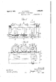
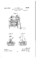
Other objects of my invention wi lfmQ fi clearly appear; from the '.clescriptioni"and claims hereinafter following. f l In t e r wings formi g paren -this pe i e j Fi ure 1 'te hle v ei Le e m c em yi s y improvements, parts being broken awa in, order to accom niodate the figureon the sheet. Figure Zis a fronte'l-evational viewioflthe machine shown in Figure l and similarlybroken aiwayf Figure3.1s a vertical transverse sectional View corresponding to the hue ,otFigure 1,
larly the first pressure roller. In .thisfigure is alsoinldicated in-dotted lines, theoriginal' position: assumed by the" belt fastener means. Figure 5 is a View similar to 'Figure llbutfillustratingtheda'st pressure roller. Figurefi 1 Figure is an enlarged vertical sectional View corresporidlng approxlmatelyf to the line L-{ of Figure '1 ancl'show ng more. pardon;
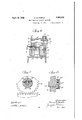
is ,al transyerse verticallsectionalyiew corre V spending to "the line .656 of Figure l. c. 7 1s anfenlarged detail yiew corresponding to the line 7+7 of Figured And Figurefi is a detail sectional View corresponding to the line:8,8 of Eigure fi.
Insaid draayings, ,the main support or bed plate of theamachin'e is indicated ati1Q,,the
same preferably being inihe form .of an inverted heavy channel, and which may gbegol any desired length, corresponding to the maximum width of belt or pgqn tdh'e lai i d In this connection, it will be understood that the term beltl, hereinafter employed, is usecl n a generic sense to 1nclude not only belts of leather but belts or. apronsof fabric or othenmaterial. Mountdpnthegbed plate lO is'a rearrack supporting platell, secured 1n place by suitable bolts 12. 1 'On top of the] P e e' is e e h esie "geeepee 'e' 59 a purpose hereinafter specified and on top of the latter is a rack 14, which extends the length of the machine, said rack 14 and plate 13 being secured by a plurality of bolts: 15 at suitable intervals therealong.
Along the front edge of the bed plate 10 extends a heavy plate 16 to which is secured an inwardly overhanging guide plate 17, and on the top of the latter is secured the belt fastener means holder 18, said plates 16 and 17 and holder 18 extending the full length of the machine, as will be understood. Also inserted in the top face of the plate 17 is a preferably case hardened anvil plate 19 against which the lacings or fasteners are clinched, as will be understood. With this construction, as clear from the drawings, a horizontal table or support is provided not only for the lacings or fasteners but for the beltfend 20. As will be further understood, the holder 18 is detachably or removably secured in position by countersunk screws 21 so that different holders may be used with the same apparatus. Bodily movable lengthwise of the machine is a carriage, the main casting of which is indicated by the reference character A. Said carriage is relatively elongated and is formed with three generally semi-circular housings 22, 23 and 24 along the rear side and also with web sections 2525 providing three sets of bearings for the pinions and pressure rollers, hereinafter described. The carriage casting A is further provided with depending web sections 26, with which are cast integrally two journal bearings 27 for the guide rollers hereinafter described. Journaled in the three sets of upper journal bearings are three shafts 28, 29 and 30, respectively. To the front or outer ends ofthese shafts are keyed or otherwise secured three pressure rollers 31, 32 and 33, respectively, said rollers being so positioned, as shown in Figure 2, that their effective bearing surfaces are progressively downwardly set from left to right so as to effect a progressive setting and clinching of the fastener means, as hereinafter explained.
Journaled in the two lower bearing sections 2727, which are preferably located under the first and last pressure rollers 31 and 33, respectively, are two shafts 131131, each of which carries at its front and rear ends a guide roll-er 132132, the latter being preferably, in turn, mounted on the shafts 131 by anti-friction ball bearings 133-133, as best shown in Figure 3. The guide rollers 132 engage .under the guide plates 13 and 17, and obviously prevent the carriage A from lif ing up and consequently the-exertion of pressure on the fastener means by the pressure rollers. The front guide plate 17 is also preferably provided with a longitudinally extending groove 34 in which works a corresponding guide flange 35 formed on the earriage casting, so as to maintain the true path of longitudinal travel of the carriage in its movements back and forth on the machine.
Secured to the rear or inner ends of the two advance shafts 28 and 29 are pinions 36-36. The details of the connection to the respective shafts is shown best in Figures 6, 7 and 8. As there shown, each shaft is cut away at its inner end so as to provide a flange section 37 within the hubportion 38 of the pinion.
Each hub portion 38 carries two set screws 39-39 cooperable with the flange section 37 so that the pinion can be adjusted angularly with respect to the shaft, which in turn provides for the angular adjustment between the pinions and the respective pressure rollers 31 and 32 at the other'ends of the shafts, for the purpose hereinafter described. The third shaft 30 carries at its rear end another pinion 40, which may be keyed or pinned as shown in Figure 3 and said shaft 30 also carries an operating handle 41. 'As will be understood, all pinion-s 36 and 40 cooperate with the rack 14 so that, upon rotation of the handle 41, positive movement longitudinally of the machine is imparted to the carriage and all three pressure rollers are simultaneously and positively rotated. In the case of the'last or final pressure roller 33, the front end of its shaft 30 is preferably adjustable vertically in an anti-friction ball bearing 42, by means of a set screw 43, so that the distance between the active plane surface of the roller 33 and the anvil plate 19 can be accurately gauged and adjusted.
The two advance pressure rollers 31 and 32 are of like construction, each being preferably splined to its corresponding shaft. Each of said rollers has its periphery provided with a series of teeth 44-44, which are inclined from upper left downwardly to lower right, as viewed in top'plan and as shown in Figure 1. As will be understood, the teeth on the underside of said pressure rollers where the same engage with the prongs 45 ofthe fastener means, as shown best in Figures 4 and 6, will have the teeth all sloping in the opposite direction. Said teeth 44 are of a pitch or are so spaced as to correspond accurately with the spacing of the prongs 45 of the fastener means, whether the latter be of the continuous belt lacing type or the individual hook type. As previously described, the angular adjustment provided for between the pressure rollers 31 and 32 and their respective pinions 36 permits of the accurateadjustment of the teeth 44, with the notches 46 of the holder 18 that carries and positions the fastener means 45, the latter being held in place by a gauge pin 47, as will be understood. In this way,
it will be seen that the teeth 44 of the first and second rollers are accurately adjusted so that each prong of the fastener means will be straddled by or engaged between two adjacent teeth of the respective pressure rollers and thereby positively and accurately maintained in proper-positionwithout dan ger of the prongs "being pushed or offset.
tion of movement of the carriage so as to ing obtained from the three rollers.
preserve the proper alinement of thefprongs and thereby compensate for the shift of the prongs'which might otherwiseoccur,due to the bodily movement ofthe pressurerollers simultaneously with the depressing-or inibedding of the fastener prongs. By progres sively setting the pressurerollers as herein before stated, the first roller 31 willserveto initially imbed the prongs'inthe'belt; the second pressure roller 32 will continue the deformation and imbedding and the final pressure roller 33 with the plane surface, after the prongs have been sufiiciently set so that displacement can no longer occur, will complete'the imbedding and ultimate Q clinching over of the prongs.
From the preceding description, taken in connection with the drawings, it will be seen that no preliminary hanimering'down ofthe fastener means is necessarybut, on the contrary, the fastener means may be inserted and held in the holder, the end of thebelt inserted between the prongs and then the carriage reciprocated' and a complete clinch- Further, the use of toothed pressure rollers insures the maintenance of proper alinement of the prongs, thereby eliminating any tendency of the fastener meansto buckle or creep with respect to the end .of the belt and a final smooth and neat application obtained.
As will be understood by those skilled in the art, the toothed pressure rollers 31- and 32 may be interchanged for others of dif ferent pitch, corresponding to the spacing of the notches 46 of the holder 18, if different size fastener means are employed.
Although I have herein shown and described what I now consider the preferred manner of carrying out my invention, the same is merely illustrative and I contemplate all such changes and modifications as come Within the scope of the claims appended hereto.
I claim: 1. In a machine of the character described,
the combination with a frame of means thereon for holding a length of pronged belt fastener means in position to receive the end of a belt inserted within the prongs; a carrier mounted on said frame toreciprocate lengthwiseof said holding means; and a plurality of rollers on said carriage successively engageable with the fastener means as the carriage is reciprocated, the advance roller having its periphery formed to'indiyid-ual-ly straddle the -prongs.
2. In amachine ofthe'character described, the combination with a frameyof; means thereon. for holding a length of prongedbelt fastener means in position'toreceive the end of a belt inserted withint'heprongs 351F211:
rier mounted on said frame to reciprocate lengthwise" of i said i holding means and [:an advanceitoothed pressure roller: on said care riage'having theteeththereof engageahle'hetweentheipro-ngs; and a rear planesurfaco,
pressure roller on said carriage-for effecting,
final clinching of the prongs.
:In avmachine of thecharacter described,
the combination: with .a supporting frame of means thereon for holding a 'l'engthiof, rpr'ongedbelt fastener meansiinrpositioneto receive the .endzof a belt. within the prongs;
prong-setting and space-retaining means mounted .on said frame and movable leirgtlr wise of said holdingmeans and individually and selectively engageablewith theprongs; and additional means for further setting -.and clinching the prongs also mounted on .said
frame and movable lengthwise of said holding' means.
4. Ina machine of the character described, I
the combination with a frame;:;o:f-means fastener means in position to receive the end of a belt insertedwithin the prongs;avpressure roller mounted to reciprocate length wise of said holding meanswand' havinga notched periphery to selectively straddle the prongs and initially set' the same in -thesbelt end; and an additional= pressure roller also mounted to reciprocate lengthwise ofsaid holding-means to further setthe prongs.
thereon for holding a length of pronged belt fastener means in position toareceiveithe end of a belt inserted within the prongs; t wo set pressure :rollers, xaeach.
progressively mounted to reciprocate lengthwise ofsaid holding means and having notched periph- V eries to individually straddle the prongs and progressively setthe'sameg-and a final pres- 7 sure roller also reciprocally mounted. V o v 6; "In a machme of the character described,
the combination witha frame; of a holder thereon for belt fastener-means with prongs uniformly spaced, means for setting the prongs into a beltend includingv a roller having. a1 periphery notched to correspond with the spacingof the prongs; a reciprocall-yf mounted carriage for supportin-gxsaid roller; -means for positively reciprocating said carriage including a rack and pinion;
thereon'for holding a lengthof pronged belt 95 1:5. In amachine of the character described, Q 59 the combination with a frame;ofnne'ans the pressure roller and pinion whereby to accurately position the notches of thepressure roller with reference to the prongs.
8. In a machine of the character described,
the combination with a frame; of a holder thereon for retaining belt fastener means with prongs uniformly spaced; a carriage mounted for longitudinal movement with ref erence to said holder; a plurality of pressure rollers mounted in said carriage and adapted to successively engage the fastener means, certain of said rollers having notched peripheral surfaces to receive the prongs; and means for imparting positive rotation to said notched pressure rollers including a fixed rack, a pinion associated with each of said rollers, and devices for angularly adjusting each notched pressure roller with respect to its respective pinion.
9. In a machine of the character described, the combination with a supporting frame having a holder for a length of belt fastener means thereon and a parallel rack; of a car riage adapted to reciprocate lengthwise of said holder; three pressure rollers mounted on said carriage and progressively set with their peripheral surfaces adapted to successively engage the fastener means and set the same, the first two of said rollers having notched peripheries to receive the prongs of the fastener means; shafts fixed to each of said pressure rollers and each carrying a pinion cooperable with said rack; and means for angularly adjusting each notched roller with respect to its pinion.
10. In a machine of the character described, the combination with a frame; of holding means thereon for retaining belt fastener means having a plurality of uniformly spaced prongs therealong and within which prongs the end of a belt is adapted tobe inserted; and a plurality of pressure-applying devices movable on said frame lengthwise of said holding means, certain of said devices having the pressure-applying surface provided with recesses uniformly spaced to correspond with the spacing of the prongs and adapted to receive the latter therewithin while being moved lengthwise of the holding means. I
11. In a machine of the character described, the combination with a frame; of fixed holding means thereon for belt fastener means having uniformly spaced prongs therealong; a pressure-applying roller having recesses in its periphery uniformly spaced to correspond withthe spacing of the prongs and within which recesses the prongs are adaptedto be individually received as the roller moves lengthwise of said holding means; a carrier mounted on said frame to reciprocate parallel to said holding means and in which said roller is journaled; cooperable means on the roller journal and frame for positively effecting rotation of said roller in timed relation with respect to said holding means when said carrier is reciprocated; and additional pressure-applying means also engageable with the prongs of the belt fastener means after the latter have been engaged by said roller.
In witness that I claim the foregoing I have hereunto-subscribed my name this 9th day of July, 1930.
GEORGE E. PURPLE.
Priority Applications (1)
| Application Number | Priority Date | Filing Date | Title |
|---|---|---|---|
| US473833A US1853928A (en) | 1930-08-08 | 1930-08-08 | Belt fastener applying machine |
Applications Claiming Priority (1)
| Application Number | Priority Date | Filing Date | Title |
|---|---|---|---|
| US473833A US1853928A (en) | 1930-08-08 | 1930-08-08 | Belt fastener applying machine |
Publications (1)
| Publication Number | Publication Date |
|---|---|
| US1853928A true US1853928A (en) | 1932-04-12 |
Family
ID=23881187
Family Applications (1)
| Application Number | Title | Priority Date | Filing Date |
|---|---|---|---|
| US473833A Expired - Lifetime US1853928A (en) | 1930-08-08 | 1930-08-08 | Belt fastener applying machine |
Country Status (1)
| Country | Link |
|---|---|
| US (1) | US1853928A (en) |
Cited By (3)
| Publication number | Priority date | Publication date | Assignee | Title |
|---|---|---|---|---|
| US5020209A (en) * | 1989-11-06 | 1991-06-04 | Flexible Steel Lacing Company | Belt lacing and cutter assembly |
| US5680688A (en) * | 1996-02-15 | 1997-10-28 | Garner; James Melvin | Portable apparatus for affixing a lacer to a belt |
| US6311393B1 (en) | 1999-08-25 | 2001-11-06 | James M. Garner | Assembly for attaching fasteners to a belt |
-
1930
- 1930-08-08 US US473833A patent/US1853928A/en not_active Expired - Lifetime
Cited By (3)
| Publication number | Priority date | Publication date | Assignee | Title |
|---|---|---|---|---|
| US5020209A (en) * | 1989-11-06 | 1991-06-04 | Flexible Steel Lacing Company | Belt lacing and cutter assembly |
| US5680688A (en) * | 1996-02-15 | 1997-10-28 | Garner; James Melvin | Portable apparatus for affixing a lacer to a belt |
| US6311393B1 (en) | 1999-08-25 | 2001-11-06 | James M. Garner | Assembly for attaching fasteners to a belt |
Similar Documents
| Publication | Publication Date | Title |
|---|---|---|
| US1853928A (en) | Belt fastener applying machine | |
| CN106488988A (en) | Leather press machine | |
| US2509354A (en) | Pressing machine | |
| DE865274C (en) | Method and device for wrapping objects of any shape, especially fragile objects | |
| US3669324A (en) | Cover material feeding and forming apparatus for a quilting machine | |
| DE1760952C3 (en) | Device for ironing or embossing leather | |
| US2336535A (en) | Wood bending machine | |
| US2333998A (en) | Machine for finishing edges of underpadding | |
| US1919639A (en) | Tile machinery | |
| US2497043A (en) | Apparatus, including rolls with mandrel gripping and work contacting portions for making curved profiles | |
| US2636455A (en) | Dough molder pressure board mounting | |
| US2202016A (en) | Manufacture of metal articles | |
| US1821337A (en) | Apparatus for and method of printing or embossing pencils | |
| US1661316A (en) | Scutching machine | |
| ITBO970576A1 (en) | MACHINE TOOL FOR PANEL PROCESSING. | |
| DE654141C (en) | Polishing machine for flat workpieces | |
| US2530573A (en) | Machine for performing putting-out or analogous operations on hides or skins | |
| US1710894A (en) | Belt-lacing machine | |
| US1740959A (en) | Machine for inserting belt lacings | |
| US1637030A (en) | Method and means for feeding articles | |
| US2614411A (en) | Machine for roughening leather and plastic materials | |
| US3197991A (en) | Apparatus and method for tapering bars | |
| US1924257A (en) | Cloth forming mechanism | |
| GB1507114A (en) | Apparatus for producing conveyor belts | |
| DE643089C (en) | Machine for planing leather |