US1853893A - Draft appliance for locomotives - Google Patents
Draft appliance for locomotives Download PDFInfo
- Publication number
- US1853893A US1853893A US348750A US34875029A US1853893A US 1853893 A US1853893 A US 1853893A US 348750 A US348750 A US 348750A US 34875029 A US34875029 A US 34875029A US 1853893 A US1853893 A US 1853893A
- Authority
- US
- United States
- Prior art keywords
- passageway
- draft
- smoke
- smoke box
- upwardly
- Prior art date
- Legal status (The legal status is an assumption and is not a legal conclusion. Google has not performed a legal analysis and makes no representation as to the accuracy of the status listed.)
- Expired - Lifetime
Links
- 230000003137 locomotive effect Effects 0.000 title description 6
- 239000000779 smoke Substances 0.000 description 23
- 239000007789 gas Substances 0.000 description 5
- 238000002485 combustion reaction Methods 0.000 description 4
- 238000010276 construction Methods 0.000 description 4
- 238000005266 casting Methods 0.000 description 3
- 206010022000 influenza Diseases 0.000 description 3
- 238000009434 installation Methods 0.000 description 2
- 238000005304 joining Methods 0.000 description 2
- 238000012423 maintenance Methods 0.000 description 2
- 238000004519 manufacturing process Methods 0.000 description 2
- 239000003818 cinder Substances 0.000 description 1
- 238000004140 cleaning Methods 0.000 description 1
- 230000002950 deficient Effects 0.000 description 1
- 238000012986 modification Methods 0.000 description 1
- 230000004048 modification Effects 0.000 description 1
- 238000005192 partition Methods 0.000 description 1
Images
Classifications
-
- F—MECHANICAL ENGINEERING; LIGHTING; HEATING; WEAPONS; BLASTING
- F23—COMBUSTION APPARATUS; COMBUSTION PROCESSES
- F23L—SUPPLYING AIR OR NON-COMBUSTIBLE LIQUIDS OR GASES TO COMBUSTION APPARATUS IN GENERAL ; VALVES OR DAMPERS SPECIALLY ADAPTED FOR CONTROLLING AIR SUPPLY OR DRAUGHT IN COMBUSTION APPARATUS; INDUCING DRAUGHT IN COMBUSTION APPARATUS; TOPS FOR CHIMNEYS OR VENTILATING SHAFTS; TERMINALS FOR FLUES
- F23L17/00—Inducing draught; Tops for chimneys or ventilating shafts; Terminals for flues
- F23L17/16—Induction apparatus, e.g. steam jet, acting on combustion products beyond the fire
Definitions
- the present invention relates to draft ap- Another object of the invention is to propliances for steam locomotives, and more vide a mechanism whereby the leaks heretoparticularly'to, improved means cooperating fore present in the smoke box are eliminated. withthe exhaust jet in the'smoke box to-jin- Other-objects of the inventionwillhereinduce an efficient forced draft through the after appear.
- V, v j p disposed in the "lower part of the smoke box,
- whic'h is herein exemplified, there "is nozzle to permit the smoke. and gases in the provided in the smokebox, 10, of the locomosmokebox to become entrained with the jet. 'tive, an independent passageway, 11, leading To develop with such mechanism, a draft of from a point forward of the boiler flues, 12, p
- An object of the present invention is to prosuflicient velocity to make the mechanism self vide a forced draft appliance whereby the cleaning in theusual mannen' various disadvantages inherent in the de-
- the lift pipe 16 comprises three main por-' scribed prior constructions are overcome.
- tions viz: alower portion,-16a,which con- 40
- Another object of the present invention is tains the exhaust nozzle, and is joined to the '90 to combine the exhaust nozzle, and lift pipe draft pipe, an intermediate portion, 16b,havin a single integral casting, whereby a subing walls which converge upwardly above the stantial economy in manufacturing, installanozzle, and atop portion, 160, having walls tion, and maintenance costs is effected and which diverge upwardly from the intermedicentralization of the steam jet with the lift ate portion.
- the construction is analogous to pipe is insured. the well knowniventuri tube.
- a further object of the .inv'ention is to pro- It is to be particularly noted that by formvide a mechanism. which will produce an efing the draft pipe and the lift pipe as deficient forced draft without the development scribed,the passageway, 11, is ofmaximum of undesirable back pressure on the pistons.
- cross sectional effective area, at the dia- L trated body of gases, is that it enables a'rela tively large jet to be used, compared to that formerly required, thus practically eliminating back pressure on the, pistons.
- the lift pipe, and exhaust nozzle are preferably. formed as one-piecein'tegral casting, whereby :a substantial economy in manufacturing, installation, and maintenance costs is effected, andian' accurate: central alignment of the nozzle with the lift pipe is'insured.
- Another advantage of the improved construction is thzatit is essentially comprised in two main parts, 6 thus eliminating the chance of varying from the original installation in taking down and reassembling the apparatus.
- boiler havingfiues; a smoke box forward of the fiues; an unbroken passageway therein forleading products of combustion forward- :ly ofthesmoke box and out-through thetop :10!)
- a passageway for the products of combustion inthe forward end of said smoke box comprising an intermediate portion having upwardly converging walls, an upper portion adjacent the intermediate portion having upwardly diverging walls therebyfforming a throat atthe juncture of the converg .ing and diverging walls, a lower'portion open 12 at its rear adjacent the in intermediate portion, and forwardly converging walls connectingsaid openingswhereby a passageway having enclosing. side walls. and'open ends is provided 'forconveylng the products of com- 1 bustion; and an exhaust nozzle extending up wardly through said lower portion having an outlet concentric with the said throat.
- An integral casting for a locomotive smoke box comprising a passageway including a lower portion having an openlng at the c rear for the admission of the products of combustion, an intermediate portion adjacent the lower portion having upwardly converging. walls, an upper portion adjacent the intel-mediate portlon having upwardly diverging walls thereby forming a throat at the juncture of the converging and diverging walls; and an exhaust nozzle, having a lower
Landscapes
- Engineering & Computer Science (AREA)
- Chemical & Material Sciences (AREA)
- Combustion & Propulsion (AREA)
- Mechanical Engineering (AREA)
- General Engineering & Computer Science (AREA)
- Chimneys And Flues (AREA)
Description
"FIG J:
April 12, 1932.
A. W. BRUCE DRAFT APPLIANCE FOR LOCOMOTIVES Filed March 21, 1929 -1 and enters the flaring lower end of a lift pipe descriptively to the I specific embodiment 65 -30 nozzle to be disposed out of central'align plate, the'top wall, a, being formed with 80 Patented 12 1932 j p a Q UNITED STATES, PATEN OFFICE? v i i V l i V w ucaomaw YoRK,-' 1\T i Dream APPLIANCE non jnoc' j j tion filed March 21, 1929. Serial No. 348,750;
The present invention relates to draft ap- Another object of the invention is to propliances for steam locomotives, and more vide a mechanism whereby the leaks heretoparticularly'to, improved means cooperating fore present in the smoke box are eliminated. withthe exhaust jet in the'smoke box to-jin- Other-objects of the inventionwillhereinduce an efficient forced draft through the after appear. V
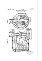
flues of the'boiler. a In the accompanying drawings, Figure Q Heretofore, the usualpractice for induc- 1 is a fragmental longitudinal vertical central ing aforced draft through the fines of 1000- section of the forward end of alocomotive motive boilers has been to entrainthe smoke embodyingthe invention; and Fig. 2, a trans- 10 and gases which enter the smokebox, in a jet verse vertical section, the right hand half to of exhaust steam from the cylinders, by takenfon theline B B and the lefthand half whichjet they are carried out of the stack. on the line A A, of themechanism'sh own in The jet of exhaust steam flows from a nozzle Figure 1. V, v j p disposed in the "lower part of the smoke box, In the practice of the invention, referring spaced aconsiderable distance above the thereof, whic'h is herein exemplified, there "is nozzle to permit the smoke. and gases in the provided in the smokebox, 10, of the locomosmokebox to become entrained with the jet. 'tive, an independent passageway, 11, leading To develop with such mechanism, a draft of from a point forward of the boiler flues, 12, p
proper efficiency, it was necessary to employ and superheater pipes, 13, out of the stack, 14. 170 a concentrated powerful jet of steam, and The passageway, 11, is formed of three main consequently undesirable back pressure on sections, viz: a draft pipe, 15, a lift pipe, 16, the pistons was present. "Further objectionand the smoke stack 14. i V able features-of the old mechanism,werethe The space within the smoke box is partitortuous routes in the smoke box which the tioned'ofi' forwa'rdlyof the superheater'pipes 75 smoke and gases had to traverse before reachby a diaphragm plate, 17, formed with a large ing the steam jet'and the dead spaces that central opening communicating with the were present in the smoke box. Another obdraft pipe,f15. Thewalls of the draft pipe jectionablefeature was the liability of the converge forwardly from the diaphragm ment with .the lift pipe, with consequent ima manhole which is closed by the cover plate, 'pairment of the efficiency of the'jet- Another 15?), Within the'draft pipe is a damper, 150, objectionable feature, was the leaks present and a sheet of wire netting, 15d. The damper at theplaces where thevarious fittings were is provided with a wall suitably inclined attached. I to project the cinders against the netting with '85 An object of the present invention is to prosuflicient velocity to make the mechanism self vide a forced draft appliance whereby the cleaning in theusual mannen' various disadvantages inherent in the de- The lift pipe 16 comprises three main por-' scribed prior constructions are overcome. tions, viz: alower portion,-16a,which con- 40 Another object of the present invention is tains the exhaust nozzle, and is joined to the '90 to combine the exhaust nozzle, and lift pipe draft pipe, an intermediate portion, 16b,havin a single integral casting, whereby a subing walls which converge upwardly above the stantial economy in manufacturing, installanozzle, and atop portion, 160, having walls tion, and maintenance costs is effected and which diverge upwardly from the intermedicentralization of the steam jet with the lift ate portion. The construction is analogous to pipe is insured. the well knowniventuri tube.
A further object of the .inv'entionis to pro- It is to be particularly noted that by formvide a mechanism. which will produce an efing the draft pipe and the lift pipe as deficient forced draft without the development scribed,the passageway, 11, is ofmaximum of undesirable back pressure on the pistons. cross sectional effective area, at the dia- L trated body of gases, is that it enables a'rela tively large jet to be used, compared to that formerly required, thus practically eliminating back pressure on the, pistons.
The lift pipe, and exhaust nozzle are preferably. formed as one-piecein'tegral casting, whereby :a substantial economy in manufacturing, installation, and maintenance costs is effected, andian' accurate: central alignment of the nozzle with the lift pipe is'insured.
An importantadvantage of the improved construction is thatF-by conducting the smoke or gases throughan independent passage-in the smoke boxythe necessityheretofore .present, of maintaining air tight joints for all attachments in advance :of the diaphragm plate,.is eliminated.
Another advantage of the improved construction is thzatit is essentially comprised in two main parts, 6 thus eliminating the chance of varying from the original installation in taking down and reassembling the apparatus.
While one ofthepreferred embodiments of .the invention has been described, it is toibe understood that various modifications in form,assenib1y,and details, maybe resorted .to without departing from the spirit and scope of the inventiondefinedin the following claims.
The invention claimed, and desired to bev securedby Lctters PPatent, is
1. 'Inra locomotive the combination of, a boiler havingiflues a smoke boxhaving. atop 'wall, 'forward'of the fines an-unbroken draft passageway comprising a portion leading from a point forward of r the fines longitudinally through the smoke'boxtowardithe front thereof, and a portion. above the; longitudinal portion leading verticallyeupward from the ilongitudinaliportion and out through the top wall *of the smoke box, *thesaid passageway having a bottom wall:inclinedupwardly to ward the front oftheasmoke box; and anexhaust nozzle projecting through: said bottom wall and extending upwardly through said longitudinal portion and opening within the from a:point forward of'ithezboiler fluesrlon- *gitudinally through the: smoke box :toward the front thereof, and a portion above the longitudinal portion joining 'said longitudinal openingwithin said portion and leading vertically upward therefrom through the top wall of the smoke box, the said vertical portion having the form of a Venturi passageway, the said draft passageway having a bottom wall inclined upwardly toward the front of the smoke box; and an exhaust nozzle projecting through said lino-lined bottom wall ,into the passageway and extending through said longitudinal portion and opening within said vertical portion-ofthe passageway, the said nozzle being disposed in axial alignment with the vertical Venturiportion of the passageway.
3. .In alocomotive, the combination of, a boiler having fiues; a smoke box forward of so the fines; a tubular unbroken passageway for conductingproductsof combustion forwardlyof thesmoke boxand outthrough the top thereof, the said passageway comprising a vertical portion having the form of a Venturi 1st tube and a longitudinal forwardlytapering portion leading from apoint forward of the boiler fines and joined at its forward end, on its upper-side, to the base of the Venturi portion; and an exhaust nozzle projecting ,eo into the .passagewayand extending upwardly through said lon itudinal portionand Xnturi portion, thesaid exhaustmozzle being in axial alignment with the Venturiportionthereof. 1
i. In a locomotive,?the combination of, a
boiler havingfiues; a smoke box forward of the fiues; an unbroken passageway therein forleading products of combustion forward- :ly ofthesmoke box and out-through thetop :10!)
thereof, comprising a-longitudinal forward- ,ly tapering portion leading frorn'a-pointforwardof the boiler flues toward the front of thesmoke box, a verticalupwardly tapering portion joining the longitudinal portion at i its forward endon the upper sidethereof,
'and a'vertical upwardly flaring portion joiningthe-vertical upwardly tapering portion;
ing within the vertical upwardly tapering :portionof the passageway.
5. In a locomotive, the combination of-a smoke box, a partition separating ,the front portion from the rear portion'of thesmoke box, saidpartit-io-n having an opening therein; a passageway for the products of combustion inthe forward end of said smoke box comprising an intermediate portion having upwardly converging walls, an upper portion adjacent the intermediate portion having upwardly diverging walls therebyfforming a throat atthe juncture of the converg .ing and diverging walls, a lower'portion open 12 at its rear adjacent the in intermediate portion, and forwardly converging walls connectingsaid openingswhereby a passageway having enclosing. side walls. and'open ends is provided 'forconveylng the products of com- 1 bustion; and an exhaust nozzle extending up wardly through said lower portion having an outlet concentric with the said throat.
6. An integral casting for a locomotive smoke box, comprising a passageway including a lower portion having an openlng at the c rear for the admission of the products of combustion, an intermediate portion adjacent the lower portion having upwardly converging. walls, an upper portion adjacent the intel-mediate portlon having upwardly diverging walls thereby forming a throat at the juncture of the converging and diverging walls; and an exhaust nozzle, having a lower
Priority Applications (1)
| Application Number | Priority Date | Filing Date | Title |
|---|---|---|---|
| US348750A US1853893A (en) | 1929-03-21 | 1929-03-21 | Draft appliance for locomotives |
Applications Claiming Priority (1)
| Application Number | Priority Date | Filing Date | Title |
|---|---|---|---|
| US348750A US1853893A (en) | 1929-03-21 | 1929-03-21 | Draft appliance for locomotives |
Publications (1)
| Publication Number | Publication Date |
|---|---|
| US1853893A true US1853893A (en) | 1932-04-12 |
Family
ID=23369375
Family Applications (1)
| Application Number | Title | Priority Date | Filing Date |
|---|---|---|---|
| US348750A Expired - Lifetime US1853893A (en) | 1929-03-21 | 1929-03-21 | Draft appliance for locomotives |
Country Status (1)
| Country | Link |
|---|---|
| US (1) | US1853893A (en) |
-
1929
- 1929-03-21 US US348750A patent/US1853893A/en not_active Expired - Lifetime
Similar Documents
| Publication | Publication Date | Title |
|---|---|---|
| US1853893A (en) | Draft appliance for locomotives | |
| US1185008A (en) | Locomotive. | |
| US2009727A (en) | Steam generator | |
| US1045577A (en) | Smoke-consuming apparatus. | |
| US1372976A (en) | Locomotive draft appliance | |
| US1069105A (en) | Water-tube boiler. | |
| US130820A (en) | Improvement in spark arresters and consumers for locomotives | |
| US666392A (en) | Locomotive-boiler. | |
| US1050451A (en) | Locomotive-feed-water heater. | |
| US783998A (en) | Smoke-consumer. | |
| US1392080A (en) | Superheater in steam-boilers | |
| US552671A (en) | Fire-box for locomotives | |
| US123437A (en) | Improvement in steam-boilers | |
| US1474116A (en) | Boiler construction | |
| US1097692A (en) | Air-superheater for steam-boiler furnaces. | |
| US1386050A (en) | Draft-equalizer for steam-boilers | |
| US469844A (en) | Edward e | |
| US782488A (en) | Steam-boiler superheater. | |
| US1536650A (en) | Furnace attachment | |
| US361738A (en) | Spark-arrester | |
| US1059378A (en) | Locomotive. | |
| US794566A (en) | Locomotive-boiler. | |
| US1346334A (en) | Water-heater for boilers | |
| US416958A (en) | John sharket | |
| US928880A (en) | Locomotive-boiler. |