US1853831A - Toy pistol - Google Patents
Toy pistol Download PDFInfo
- Publication number
- US1853831A US1853831A US478713A US47871330A US1853831A US 1853831 A US1853831 A US 1853831A US 478713 A US478713 A US 478713A US 47871330 A US47871330 A US 47871330A US 1853831 A US1853831 A US 1853831A
- Authority
- US
- United States
- Prior art keywords
- trigger
- hammer
- actuating member
- strip
- projection
- Prior art date
- Legal status (The legal status is an assumption and is not a legal conclusion. Google has not performed a legal analysis and makes no representation as to the accuracy of the status listed.)
- Expired - Lifetime
Links
- 210000003414 extremity Anatomy 0.000 description 8
- 238000010276 construction Methods 0.000 description 6
- 238000004880 explosion Methods 0.000 description 3
- 235000012571 Ficus glomerata Nutrition 0.000 description 1
- 240000000365 Ficus racemosa Species 0.000 description 1
- 108010000916 Fimbriae Proteins Proteins 0.000 description 1
- 235000015125 Sterculia urens Nutrition 0.000 description 1
- 210000001217 buttock Anatomy 0.000 description 1
- 238000005266 casting Methods 0.000 description 1
- 238000004519 manufacturing process Methods 0.000 description 1
- 230000007246 mechanism Effects 0.000 description 1
Images
Classifications
-
- F—MECHANICAL ENGINEERING; LIGHTING; HEATING; WEAPONS; BLASTING
- F41—WEAPONS
- F41C—SMALLARMS, e.g. PISTOLS, RIFLES; ACCESSORIES THEREFOR
- F41C3/00—Pistols, e.g. revolvers
- F41C3/06—Cap-firing pistols, e.g. toy pistols
- F41C3/08—Cap-firing pistols, e.g. toy pistols with band supply
Definitions
- This invention relates to toy pistols and particularly such pistols ofthe automatictype designed to employ a strip or roll of caps which are progressively fed and exploded by operations of the trigger.
- the object of this invention is to provide a simple construction of this character, and one which will not jam or clog.
- the invention embodies means for positively actuating the hammer and for returning the hammer and trigger to their normal positions after each discharge.
- the invention has as one of its principal features, the provision of means for simultaneously gripping a cap strip upon opposite sides for feeding it, whereby there is no lagging of the strip such as occurs with the pistols now in use, with the result that no pilin up or twisting of the strip within the pistol will be possible.
- a further object of the invention is to effectively guide the strip, which is accomplished by the gripping means.
- These grip- )llig means are novel in their construction well operation. 1
- Figure 1 is a view with one partof the housing removed showing the parts in normal position.
- Figure 2 is a similar view showing the trigger as pulled initially and the position of the other parts.
- Figure 3 is a similar view showing the trigger pulled to the point where the hammer will be released.
- igure 5 is a detail view of the trigger, the operating member and the hammer.
- this pistol is preferably comprised of a housing or casing which as usual is made of sectional castings suitably secured together by bolts or screws 11 and 12.
- he numeral 13 indicates a suitable pin or stud adapted to receive the usual roll of caps.
- the trigger member is indicated at 14, the operating member at 15, and the hammer at 16.
- the trigger is pivotally supported within the casing and to this end is provided with an opening 17 receiving an upstanding pivot pin 17, integral with the casing.
- the trigger member is provided with a projection 18, and the pistol casing is provided with an upstanding lug 19 forming a stop for the trigger in its upward movement as shown in the drawings.
- This lug and projection receive and hold a coil spring 20 arranged on the lug 17 which is a relatively strong spring.
- the trigger member has an extension 21 terminating in an offset portion 22 having an inner flat surface 23.
- the trigger is provided with a laterally extending pin 24: for a purpose which will now be described.
- the actuating member 15 is provided with an opening 25 to receive the pin or stud 24 and is adapted to pivot thereon.
- the actuating member is provided with a recess and projection indicated at 26, and upon reference to Figures. 1, 2 and 3, it will be seen that a coil spring 27, has its coils arranged about the stud 24: with one extremity engaging beneath the projection 26 and the other end engaging the pivot 17.
- the actuating member 15 is provided with an enlarged end or extremity 28 and upon reference to Fig ures 1, 2 and 3, it will be observed that the end portion is flat as indicated at 29.
- the under surface of the actuating member is curved or ar-cuate to provide a recess 30 which terminates in a notch or projection 31 and the remainder of the edge portion of the actuating member is, also curved as shown in the detail view for a purpose which will presently be described.
- the hammer member 16 is pivoted upon a stud 32 preferably formed integral with one of the sections of the casing and said ham-
- the mer comprises a striker portion 33.
- hammer at a point adjacent its pivotal mounting is provided with a notch 34 and thesection is provided with a notch 85, said notches nates in the notch 37.
- the hammer member is provided with a projection 37 having a rounded upper surface 38, as shown in Figure 5.
- the line construction shown in Figures 1, 2 and 3 is to indicate the course of a strip of caps, which it will be observed, pass from the roll positioned about the stud 13 upwardly past the fiat face 23 of the trigger member, whereby the strip is fed to the fiat striking surface 39 of the pistol.
- the springs 20 and 36 are of greater strength than the spring 27, and these two springs acting respectively upon the trigger and the hammer serve to maintain the parts in the normal position shown in Figure 1, and to return them to that position immediately the trigger is released.
- the spring 36 maintains the hammer normally against the anvil and the spring20 maintains the trigger normally in engagement with the stop 19.
- the spring 27, of course, is a relatively weak-er spring and is designed to always keep the actuating member projected outwardly.
- the projecting portion of the hammer can fit thereunder, and, consequently, all of these parts can be placed within the usual area associated with the conventional design of a pistol.
- the lower portion of the hammer is offset as shown at 40 so that the ends of the trigger and actuating member may fit within the recess or space provided between the offset portion and the turned up portion which termi- This is important, .because bulky and unwieldly mechanisms are not generally acceptable, because they do not resemble the real article.
- a roll of caps is positioned upon the stud 13 and the end is guided between the opposed faces :23 and 29, as shown for example in Figure 1.
- the flat face 23 of the trigger When the trigger is initially pulled inwardly, it will be noted that the flat face 23 of the trigger will be moved upwardly and simultaneously with this movement when the flat face reaches the limit of its initial movement, the end of the actuating member will engage the strip in contact with the flat face of the trigger member.
- the grip ping action of the two members upon the strip is simultaneous, and one member does not move through any considerable distance, or so individually with respect to the other gripping member as to drag the strip with it and cause a piling up or twisting within the pistol.
- the actuating member is carried by the trigger member so that the two gripping surfaces are operated simultaneously and grip the strip upon opposite sides at the identical moment.
- the point or engagement of the two members with the strip is such that the an gular corner of the actuating member strikes the strip directly opposite, centrally of the flat surface of the trigger member so that there is in eifect a biting or gripping which is positive and does not allow of any loose play or slippage.
- the construction of the actuating member and the trigger member is such as to allow the provision of a relatively long foot 28, 29 and consequently this gripping action is very tenacious.
- the arcuate recess .provided at 30, 31 of the actuating member is sufficiently large to permit the gripping members to grip the strip by initial movement of the trigger so that upon further movement of the trigger the projection 31 will positively engage the projection 37 to retract the hammer.
- the desirability of this is obvious, since when the trigger is retracted to withdraw the hammer, the two gripping members are moved upwardly, gripping the strip between them to feed a cap into proper position for explosion.
- the projection 31 Upon further pulling the trigger, the projection 31 is disengaged from the projection 37 and the rounded surface 38 of the projection 37 will engage the rounded under surface of the lower edge of the actuating member so that the hammer is free to act under the force of the spring 36 to explode the cap striking the surface 39.
- the spring 20 will serve to force the trigger back to normal position and likewise the actuating member, the rounder lower edge of which will be moved downwardly with the trigger over the rounded surface '38 of the projection 3? against the tension of spring 27 to again bring the projection 37 into register with the projection 31 so that theparts are in the normal position sh own in Figure 1.
- the spring 27, it will be clear, will always serve to keep the actuating member projected and is provided as auxiliary means for positively accomplishing the gripping action.
- the actuating member not only cooperates to grip and feed the strip upwardly when the trigger is pulled, but likewise operates the hammer.
- a toy pistol comprising a casing, a trigger, a hammer, and an actuating member having integral means for operating the hammer carried by the trigger and cooperating therewith to grip and feed a strip of caps.
- a toy pistol comprising a casing, a trigger, a hammer, an actuating member having integral means for operating the hammer carried by the trigger and cooperating therewith to grip and feed a strip of caps, and
- a toy pistol comprising a casing, a trigger, a hammer, an actuating member having integral means for o crating the hammer pivotally carried by tie trigger and cooperating therewith to grip and feed a strip of caps, and springs acting upon said tr1gger, actuating member and hammer, that of said actuating member being relatively weak.
- a casing a trigger, a hammer, and an actuating member having integral means carried by said trigger for actuating the hammer and cooperating with the trigger to feed a strip of caps, and a weak spring associated with said actuating member.
- a casing a trigger memher, a hammer, an actuating member carried by the trigger member having integral means for operating the hammer and cooperating with the trigger member to feed a strip of caps, said trigger member and actuating member having opposed surfaces, one of which is flat and the other presented angularly to the flat portion when the trigger is pulled to grip the strip of caps upon opposite sides.
- a casing a trigger member, a hammer, an actuating member carried by the trigger member having integral means for operating the hammer and cooperating with the trigger member to feed a strip of caps, said trigger member and actuating member having opposed surfaces, one of which is flat and the other presented angularly to the flat portion when the trigger is pulled to simultaneously grip the strip of caps upon opposite sides.
- a casing a trigger member, a hammer, an actuating member carried by the trigger member having integral means for operating the hammer and cooperating with the trigger member to feed a strip of caps, said trigger member and actuating memher, having opposed surfaces, one of which is fiat and the other presented angularly to the flat portion when the trigger is pulled to simultaneously grip the strip of caps upon opposite sides, and springs engaging said hammer, trigger, and actuating member.
- a casing a. trigger, a hammer, an actuating member carried by the trigger having integral means for operating the hammer, the said hammer actuating memher having a gripping surface cooperating with a gripping surface formed on the trigger to grip and feed a strip of caps, one of said surfaces being flat and the other presented angularly thereto, the pulling of the trigger serving to move the gripping surfaces simultaneously into engagement with the strip and further movement of the trigger serving to simultaneously move the two members and the strip to feed a cap to the striking surface.
- a toy pistol a casing, a trigger, a
- the said hammer actuating member having a gripping surface cooperating with a gripping surface formed on the trigger to grip and feed a strip of caps, one of said surfaces being flat and the other presented angularly thereto, the pulling of the trigger serving to move the gripping surfaces simultaneously into engagement with the strip, further movement of the trigger serving to simultaneously move the two members and the strip to feed a cap to the striking surface, springs engaging said trigger and hammer, and a weaker spring acting upon said actuating member.
- a casing, a trigger, a hammer, and an actuating member carried by the trigger having integral means for actuating the hammer and cooperating with the trigger to feed a strip of caps, said actuating member having a projection and the said hammer having a projection whereby pulling of the trigger will retract the hammer and move the trigger and actuating member upwardly to feed the strip.
- a casing a trigger, a hammer, and an actuating member carried by the trigger for actuating the hammer and cooperating-with the trigger for gripping and feeding a strip of caps, said actuating member being movably supported upon the trigger and being normally urged by a spring toward a gripping surface formed on the trigger.
- a casing a trigger, a hammer, and an actuating member carried by the trigger for actuating the hammer and cooperating with the trigger for gripping and feeding a strip of caps, said actuating member being pivotally supported upon the trigger and being normally urged by a spring toward a gripping surface formed on the trigger, one edge of the said member being provided with an arcuate portion terminating in a projection and being curved on the other side of said projection.
- a housing a trigger, said trigger being pivoted upon the housing and being extended, the extended portion of the trigger being provided with an offset portion having a fiat inner surface at one end, an actuating member pivotally mounted on said trigger and having a relatively large angular extremity adjacent said flat surface, the said angular extremity being adapted to engage said flat surface upon initial movement of the trigger, and a hammer operated by the actuating member upon further movement of th trigger.
- a housing a trigger, said trigger being pivoted upon the housing and being extended, the extended portion of the trigger being provided with an offset portion having a flat inner surface at one end, an actuatingmember pivotally mounted on said trigger and having a relatively large angular extremity adjacent said flatsurface, the said angular extremity being adapted to engage said flat surface upon initial movement of the trigger, and a hammer operated by the actuating member upon further movement of the trigger, said actuating member having a projection adapted to engage a projection on the hammer and one edge of the actuating member being curved adjacent the projection thereon whereby after an explosion the said curved edge will ride over the projection of the hammer to bring the two projections into register.
- a housing a trigger, said trigger being pivoted upon the housing and being extended, the extended portion of the trigger being provided with an ofiset portion having a flat inner surface at one end, a spring projected actuating member pivotally mounted on said trigger and having a relatively large angular extremity adjacent said flat surface, the said angular extremity being adapted to engage said fiat surface upon initial movement of the trigger, a hammer operated by the actuating member upon further movement of the trigger, said actuating member having a projection adapted to engage a projection on the hammer and one edge of the actuating member being curved adjacent the projection thereon whereby after an explosion the said curved edge will ride over the projection of the hammer to bring the two projections into operating register, and springs engaging said trigger and hammer, the spring associated with the actuating member being weaker than the hammer spring whereby the curved edge of the actuating member may be moved against the tension of the spring past the projection of the hammer to accomplish the said said
Landscapes
- Engineering & Computer Science (AREA)
- General Engineering & Computer Science (AREA)
- Toys (AREA)
Description
April 12, 1932. E. s. PEAKE; 1,853,831
Filed Aug. 29, 1950 2 Sheets-Shee g toz WW MM April 12, 1932. r E. s. PEAKE TOY PISTOL Filed Aug. 29, 1930 2 Sheets-Sheet 2 gwomtox Edward S Peal Patented Apr. 12, 1932 tlhiiTE 3T 'F'E FATQENT @FFEQE EDWARD S. PEAKE, OF WESTERVILLE, OHIO, ASSIGNOR TO THE KILGORE MFG. COM- PANY, OF WESTERVILLE, OHIO, A CORPORATION OF OHIO TOY PISTOL Application filed August 29, 1930. Serial No. 478,713.
This invention relates to toy pistols and particularly such pistols ofthe automatictype designed to employ a strip or roll of caps which are progressively fed and exploded by operations of the trigger.
' The object of this invention is to provide a simple construction of this character, and one which will not jam or clog.
To this end the invention embodies means for positively actuating the hammer and for returning the hammer and trigger to their normal positions after each discharge.
Furthermore, the invention has as one of its principal features, the provision of means for simultaneously gripping a cap strip upon opposite sides for feeding it, whereby there is no lagging of the strip such as occurs with the pistols now in use, with the result that no pilin up or twisting of the strip within the pistol will be possible.
A further object of the invention is to effectively guide the strip, which is accomplished by the gripping means. These grip- )llig means are novel in their construction well operation. 1
As is well known, articles of this character are sold in tremendous quantities and it is fundamentally important that the construction be sufficiently simple as to be capable of manufacture at a minimum cost.
Referring to the drawings:
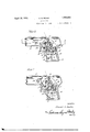
Figure 1 is a view with one partof the housing removed showing the parts in normal position.
Figure 2 is a similar view showing the trigger as pulled initially and the position of the other parts.
Figure 3 is a similar view showing the trigger pulled to the point where the hammer will be released.
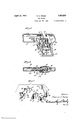
Figure at is a top View partly in section, and
igure 5 is a detail view of the trigger, the operating member and the hammer.
Referring to the drawings and particularly to Figure l, it will be understood that this pistol is preferably comprised of a housing or casing which as usual is made of sectional castings suitably secured together by bolts or screws 11 and 12.
he numeral 13 indicates a suitable pin or stud adapted to receive the usual roll of caps.
Referring to Figure 5, the trigger member is indicated at 14, the operating member at 15, and the hammer at 16.
The triggeris pivotally supported within the casing and to this end is provided with an opening 17 receiving an upstanding pivot pin 17, integral with the casing. The trigger member is provided with a projection 18, and the pistol casing is provided with an upstanding lug 19 forming a stop for the trigger in its upward movement as shown in the drawings. This lug and projection receive and hold a coil spring 20 arranged on the lug 17 which is a relatively strong spring. The trigger member has an extension 21 terminating in an offset portion 22 having an inner flat surface 23.
The trigger is provided with a laterally extending pin 24: for a purpose which will now be described.
The actuating member 15 is provided with an opening 25 to receive the pin or stud 24 and is adapted to pivot thereon. The actuating member is provided with a recess and projection indicated at 26, and upon reference to Figures. 1, 2 and 3, it will be seen that a coil spring 27, has its coils arranged about the stud 24: with one extremity engaging beneath the projection 26 and the other end engaging the pivot 17. The actuating member 15 is provided with an enlarged end or extremity 28 and upon reference to Fig ures 1, 2 and 3, it will be observed that the end portion is flat as indicated at 29. The under surface of the actuating member is curved or ar-cuate to provide a recess 30 which terminates in a notch or projection 31 and the remainder of the edge portion of the actuating member is, also curved as shown in the detail view for a purpose which will presently be described.
The hammer member 16 is pivoted upon a stud 32 preferably formed integral with one of the sections of the casing and said ham- The mer comprises a striker portion 33.
hammer at a point adjacent its pivotal mounting is provided with a notch 34 and thesection is provided with a notch 85, said notches nates in the notch 37.
receiving a spring 36 which acts upon the hammer.
At one end the hammer member is provided with a projection 37 having a rounded upper surface 38, as shown in Figure 5.
The line construction shown in Figures 1, 2 and 3 is to indicate the course of a strip of caps, which it will be observed, pass from the roll positioned about the stud 13 upwardly past the fiat face 23 of the trigger member, whereby the strip is fed to the fiat striking surface 39 of the pistol.
At this point it will be stated that the springs 20 and 36 are of greater strength than the spring 27, and these two springs acting respectively upon the trigger and the hammer serve to maintain the parts in the normal position shown in Figure 1, and to return them to that position immediately the trigger is released. The spring 36 maintains the hammer normally against the anvil and the spring20 maintains the trigger normally in engagement with the stop 19. The spring 27, of course, is a relatively weak-er spring and is designed to always keep the actuating member projected outwardly.
In this connection it will be noted that by making the trigger offset, it is possible to have an extended foot upon the actuating member, as shown at 28, 29, since this foot will be positioned within the recess formed between extension 22 and the body portion of the trigger. By having a relatively wide and broad gripping surface, due to the construction, a very effective gripping as well as guiding of the cap strip is provided.
By making the actuating member arcuate on its under surface, as shown at 30, the projecting portion of the hammer can fit thereunder, and, consequently, all of these parts can be placed within the usual area associated with the conventional design of a pistol.
In this connection it will be observed that the lower portion of the hammer is offset as shown at 40 so that the ends of the trigger and actuating member may fit within the recess or space provided between the offset portion and the turned up portion which termi- This is important, .because bulky and unwieldly mechanisms are not generally acceptable, because they do not resemble the real article.
In operating the invention, a roll of caps is positioned upon the stud 13 and the end is guided between the opposed faces :23 and 29, as shown for example in Figure 1.
When the trigger is initially pulled inwardly, it will be noted that the flat face 23 of the trigger will be moved upwardly and simultaneously with this movement when the flat face reaches the limit of its initial movement, the end of the actuating member will engage the strip in contact with the flat face of the trigger member. In other words, the grip ping action of the two members upon the strip is simultaneous, and one member does not move through any considerable distance, or so individually with respect to the other gripping member as to drag the strip with it and cause a piling up or twisting within the pistol. The actuating member, it will be observed, is carried by the trigger member so that the two gripping surfaces are operated simultaneously and grip the strip upon opposite sides at the identical moment.
It will further be noted that as shown in Figure 2, the point or engagement of the two members with the strip is such that the an gular corner of the actuating member strikes the strip directly opposite, centrally of the flat surface of the trigger member so that there is in eifect a biting or gripping which is positive and does not allow of any loose play or slippage. As previously described, the construction of the actuating member and the trigger member is such as to allow the provision of a relatively long foot 28, 29 and consequently this gripping action is very tenacious. In the case of conventional pistols, this is a marked advantage because very frequently the member corresponding the trigger member strikes the strip before the other gripping member, with the result that in its movement it drags the strip, whereas in the present case the angular surface and the flat surface simultaneously grip the strip on opposite sides.
With the parts in the position shown in F igure 2, the trigger is drawn to the position shown in Figure 3, which will result in the retraction of the hammer.
It will be noted that the arcuate recess .provided at 30, 31 of the actuating member is sufficiently large to permit the gripping members to grip the strip by initial movement of the trigger so that upon further movement of the trigger the projection 31 will positively engage the projection 37 to retract the hammer. The desirability of this, of course, is obvious, since when the trigger is retracted to withdraw the hammer, the two gripping members are moved upwardly, gripping the strip between them to feed a cap into proper position for explosion.
Upon further pulling the trigger, the projection 31 is disengaged from the projection 37 and the rounded surface 38 of the projection 37 will engage the rounded under surface of the lower edge of the actuating member so that the hammer is free to act under the force of the spring 36 to explode the cap striking the surface 39.
The spring 20 will serve to force the trigger back to normal position and likewise the actuating member, the rounder lower edge of which will be moved downwardly with the trigger over the rounded surface '38 of the projection 3? against the tension of spring 27 to again bring the projection 37 into register with the projection 31 so that theparts are in the normal position sh own in Figure 1.
, 23 and 29, since the actuating member is carried by the trigger. Consequently, after each discharge, the spring 20 will return the trigger and actuating member to normal position moving the inner body portion downwardly, whereby the projection 31 is brought in register with the projection 37 and the two gripping surfaces or pro ect1ons are separated. In this downward movement or return of the trlgger, it will be clear that the hammer member does not move, but rather the curving surface or lower edge of the actuating member and its projection 31 ride past the projection 37 and rounded head 38 thereof.
The spring 27, it will be clear, will always serve to keep the actuating member projected and is provided as auxiliary means for positively accomplishing the gripping action.
It will be observed that by provision of the springs 20 and 36, effective operation of the parts in timed relation is obtained and, moreover, by the positioning of the actuating member upon the trigger, whereby it is carried, the movement of the two gripping surfaces are simultaneous.
The actuating member, it will be observed, not only cooperates to grip and feed the strip upwardly when the trigger is pulled, but likewise operates the hammer.
T he upward movement of the inner body portion of the trigger member, which causes the fiat face 23 to move upwardly, and the angular portion 28, 29 to move outwardly, results in the simultaneous gripping of the strip upon opposite sides, and the further movement of the trigger inwardly causes the gripping members to feed the strip positively to the striking surface. These gripping members in the normal position of the parts shown in Figure 1, serve as guides for the strip and it will be noted upon reference to Figure 1, that the strip moves over the upper corner of the actuating member and the ower corner of the trigger member.
The invention may, of course, be further nodiiied in a number of ways, all of which are considered to be covered in the claims which are appended hereto.
What I claim is:
1. A toy pistol comprising a casing, a trigger, a hammer, and an actuating member having integral means for operating the hammer carried by the trigger and cooperating therewith to grip and feed a strip of caps.
2. A toy pistol comprising a casing, a trigger, a hammer, an actuating member having integral means for operating the hammer carried by the trigger and cooperating therewith to grip and feed a strip of caps, and
springs acting upon said trigger and hammer.
3. A toy pistol comprising a casing, a trigger, a hammer, an actuating member having integral means for o crating the hammer pivotally carried by tie trigger and cooperating therewith to grip and feed a strip of caps, and springs acting upon said tr1gger, actuating member and hammer, that of said actuating member being relatively weak.
i. In a toy pistol, a casing, a trigger, a hammer, and an actuating member having integral means carried by said trigger for actuating the hammer and cooperating with the trigger to feed a strip of caps, and a weak spring associated with said actuating member. V
5. In a toy pistol, a casing, a trigger memher, a hammer, an actuating member carried by the trigger member having integral means for operating the hammer and cooperating with the trigger member to feed a strip of caps, said trigger member and actuating member having opposed surfaces, one of which is flat and the other presented angularly to the flat portion when the trigger is pulled to grip the strip of caps upon opposite sides.
6. In a toy pistol, a casing, a trigger member, a hammer, an actuating member carried by the trigger member having integral means for operating the hammer and cooperating with the trigger member to feed a strip of caps, said trigger member and actuating member having opposed surfaces, one of which is flat and the other presented angularly to the flat portion when the trigger is pulled to simultaneously grip the strip of caps upon opposite sides.
7. In a toy pistol, a casing, a trigger member, a hammer, an actuating member carried by the trigger member having integral means for operating the hammer and cooperating with the trigger member to feed a strip of caps, said trigger member and actuating memher, having opposed surfaces, one of which is fiat and the other presented angularly to the flat portion when the trigger is pulled to simultaneously grip the strip of caps upon opposite sides, and springs engaging said hammer, trigger, and actuating member.
8. In a toy pistol, a casing, a. trigger, a hammer, an actuating member carried by the trigger having integral means for operating the hammer, the said hammer actuating memher having a gripping surface cooperating with a gripping surface formed on the trigger to grip and feed a strip of caps, one of said surfaces being flat and the other presented angularly thereto, the pulling of the trigger serving to move the gripping surfaces simultaneously into engagement with the strip and further movement of the trigger serving to simultaneously move the two members and the strip to feed a cap to the striking surface.
9 In a toy pistol, a casing, a trigger, a hammer, an actuating member carried by the trigger having integral means for operating the hammer, the said hammer actuating member having a gripping surface cooperating with a gripping surface formed on the trigger to grip and feed a strip of caps, one of said surfaces being fiat and the other presented anvgularly thereto, the pulling of the trigger serving to move the gripping surfaces simultaneously into engagement with the strlp, further movement of the trigger serving to simultaneously move the two members and the strip to feed a cap to the striking surface and springs engaging said trigger, hammer, and actuating member.
10. In a toy pistol, a casing, a trigger, a
trigger for operating the hammer, the said hammer actuating member having a gripping surface cooperating with a gripping surface formed on the trigger to grip and feed a strip of caps, one of said surfaces being flat and the other presented angularly thereto, the pulling of the trigger serving to move the gripping surfaces simultaneously into engagement with the strip, further movement of the trigger serving to simultaneously move the two members and the strip to feed a cap to the striking surface, springs engaging said trigger and hammer, and a weaker spring acting upon said actuating member.
11. In a toy pistol, a casing, a trigger, a hammer, and an actuating member carried by the trigger having integral means for actuating the hammer and cooperating with the trigger to feed a strip of caps, said actuating member having a projection and the said hammer having a projection whereby pulling of the trigger will retract the hammer and move the trigger and actuating member upwardly to feed the strip.
12. In a toy pistol, a casing, a trigger, a hammer, and an actuating member carried by the trigger for actuating the hammer and cooperating with the trigger to feed a strip of caps, said actuating member having an integral projection and the said hammer having a projection whereby pulling of the trigger will retract the hammer and move the trigger and actuating member upwardly to feed the strip, the projection of the hammer upon further movement being disengaged'from the projection on the actuating member, to permit the hammer to strike, a spring acting upon the hammer to force it to striking position, and a spring acting upon the trigger to return it to normal position, and to bring the two projections again into register.
13. In a toy pistol, a casing, a trigger, a hammer, an actuating member carried by the trigger having integral means to actuate the hammer, said trigger and actuating member having opposed gripping surfaces, the grip ping surface of the actuating member being normally urged toward the grippingsurface of the trigger, the said actuating member being provided with means whereby the gripping surfaces simultaneously grip a strip of caps upon opposite sides when the trigger is initially moved and upon further movement of the trigger retract the hammer and feed said strip toward a striker plate.
14. In a toy pistol, a casing, a trigger, a hammer, a spring pressed actuating member carried by the trigger having integral means to actuate the hammer, said trigger and actuating member having opposed gripping surfaces, the gripping surface of the actuating member being normally urged toward the gripping surface of the trigger, the said actuating member being provided With means whereby the gripping surfaces simultaneously grip a strip of caps upon opposite sides when the trigger is initially moved and upon further movement of the trigger retract the hammer and move said strip toward a striker plate, and springs acting upon said trigger and hammer.
15. In a toy pistol, a casing, a trigger, a hammer, and an actuating member carried by the trigger for actuating the hammer and cooperating-with the trigger for gripping and feeding a strip of caps, said actuating member being movably supported upon the trigger and being normally urged by a spring toward a gripping surface formed on the trigger.
16. In a toy pistol, a casing, a trigger, a hammer, and an actuating member carried by the trigger for actuating the hammer and cooperating with the trigger for gripping and feeding a strip of caps, said actuating member being pivotally supported upon the trigger and being normally urged by a spring toward a gripping surface formed on the trigger, one edge of the said member being provided with an arcuate portion terminating in a projection and being curved on the other side of said projection.
17. In a toy pistol, a housing, a trigger, said trigger being pivoted upon the housing and being extended, the extended portion of the trigger being provided with an offset portion having a fiat inner surface at one end, an actuating member pivotally mounted on said trigger and having a relatively large angular extremity adjacent said flat surface, the said angular extremity being adapted to engage said flat surface upon initial movement of the trigger, and a hammer operated by the actuating member upon further movement of th trigger.
18. In a toy pistol, a housing, a trigger, said trigger being pivoted upon the housing and being extended, the extended portion of the trigger being provided with an offset portion having a flat inner surface at one end, an actuatingmember pivotally mounted on said trigger and having a relatively large angular extremity adjacent said flatsurface, the said angular extremity being adapted to engage said flat surface upon initial movement of the trigger, and a hammer operated by the actuating member upon further movement of the trigger, said actuating member having a projection adapted to engage a projection on the hammer and one edge of the actuating member being curved adjacent the projection thereon whereby after an explosion the said curved edge will ride over the projection of the hammer to bring the two projections into register.
19. In a toy pistol, a housing, a trigger, said trigger being pivoted upon the housing and being extended, the extended portion of the trigger being provided with an ofiset portion having a flat inner surface at one end, a spring projected actuating member pivotally mounted on said trigger and having a relatively large angular extremity adjacent said flat surface, the said angular extremity being adapted to engage said fiat surface upon initial movement of the trigger, a hammer operated by the actuating member upon further movement of the trigger, said actuating member having a projection adapted to engage a projection on the hammer and one edge of the actuating member being curved adjacent the projection thereon whereby after an explosion the said curved edge will ride over the projection of the hammer to bring the two projections into operating register, and springs engaging said trigger and hammer, the spring associated with the actuating member being weaker than the hammer spring whereby the curved edge of the actuating member may be moved against the tension of the spring past the projection of the hammer to accomplish the said registering of the projections.
In testimony whereof I have hereunto set my hand.
EDWARD S. PEAKE.
Priority Applications (1)
| Application Number | Priority Date | Filing Date | Title |
|---|---|---|---|
| US478713A US1853831A (en) | 1930-08-29 | 1930-08-29 | Toy pistol |
Applications Claiming Priority (1)
| Application Number | Priority Date | Filing Date | Title |
|---|---|---|---|
| US478713A US1853831A (en) | 1930-08-29 | 1930-08-29 | Toy pistol |
Publications (1)
| Publication Number | Publication Date |
|---|---|
| US1853831A true US1853831A (en) | 1932-04-12 |
Family
ID=23901077
Family Applications (1)
| Application Number | Title | Priority Date | Filing Date |
|---|---|---|---|
| US478713A Expired - Lifetime US1853831A (en) | 1930-08-29 | 1930-08-29 | Toy pistol |
Country Status (1)
| Country | Link |
|---|---|
| US (1) | US1853831A (en) |
-
1930
- 1930-08-29 US US478713A patent/US1853831A/en not_active Expired - Lifetime
Similar Documents
| Publication | Publication Date | Title |
|---|---|---|
| US7458494B2 (en) | Surgical stapler with sound producing mechanism to signal the completion of the stapling process | |
| TW201026449A (en) | Nail gun with safe firing mechanism | |
| US8276799B2 (en) | Front-depression stapling device | |
| US1962874A (en) | Staple setting machine | |
| US2432853A (en) | Implement for driving staples | |
| US1853831A (en) | Toy pistol | |
| US2427028A (en) | Stapling device | |
| US2574988A (en) | Stapling plier | |
| US1705819A (en) | Stapling machine | |
| US2017778A (en) | Toy airplane projector gun | |
| US2112941A (en) | Stapling machine | |
| US1829537A (en) | Stapling machine | |
| US2466856A (en) | Staple driving device | |
| US1488161A (en) | Magazine tack hammer | |
| SU25A1 (en) | Modification of the typewriter for the Turkish-Arabic font | |
| US2073959A (en) | Stapling machine | |
| US2392327A (en) | Stapling apparatus | |
| US2380785A (en) | Stapling machine | |
| US843064A (en) | Repeating cap-pistol. | |
| US1467918A (en) | Toy pistol | |
| US1905737A (en) | Toy gun | |
| US1403753A (en) | Impact-producing implement | |
| US1510450A (en) | Punch | |
| US1472153A (en) | Toy pistol | |
| US1415976A (en) | Firearm |