US1853692A - Locomotive stoker - Google Patents
Locomotive stoker Download PDFInfo
- Publication number
- US1853692A US1853692A US89652A US8965226A US1853692A US 1853692 A US1853692 A US 1853692A US 89652 A US89652 A US 89652A US 8965226 A US8965226 A US 8965226A US 1853692 A US1853692 A US 1853692A
- Authority
- US
- United States
- Prior art keywords
- fuel
- conveyor
- locomotive
- elevator
- conduit
- Prior art date
- Legal status (The legal status is an assumption and is not a legal conclusion. Google has not performed a legal analysis and makes no representation as to the accuracy of the status listed.)
- Expired - Lifetime
Links
- 230000003137 locomotive effect Effects 0.000 title description 29
- 239000000446 fuel Substances 0.000 description 52
- 238000010304 firing Methods 0.000 description 7
- 238000009877 rendering Methods 0.000 description 4
- 239000003245 coal Substances 0.000 description 3
- 235000012571 Ficus glomerata Nutrition 0.000 description 1
- 240000000365 Ficus racemosa Species 0.000 description 1
- 235000015125 Sterculia urens Nutrition 0.000 description 1
- 238000013459 approach Methods 0.000 description 1
- 238000010276 construction Methods 0.000 description 1
- 230000005484 gravity Effects 0.000 description 1
Images

Classifications
-
- F—MECHANICAL ENGINEERING; LIGHTING; HEATING; WEAPONS; BLASTING
- F23—COMBUSTION APPARATUS; COMBUSTION PROCESSES
- F23K—FEEDING FUEL TO COMBUSTION APPARATUS
- F23K3/00—Feeding or distributing of lump or pulverulent fuel to combustion apparatus
- F23K3/04—Feeding or distributing of lump or pulverulent fuel to combustion apparatus for locomotive boiler furnaces
Definitions
- This invention relates to stokers for locomotives, and has for one of its objects the provision of new and improved means for delivering increments of fuel to the fuel distributing mechanism.
- Another object of the invention is the provision of a new and improved stoker constructionin wh1ch the conveyor, the elevator tion of the fuel trough,
- a further 'object of the. invention is the new and improved mechanism for delivering fuel intermittently-to the zone of action of the distributing mechanism.
- FIG. 1 is a side elevation of a portion of a locomotive showing the invention in posiprovision of tion thereon, with parts in section and parts broken away a Fig. 2 is a section on broken line 22 of Fig. 1;
- Fig, 3 is a detail plan view of the rear porshowing the clutch
- the reference character 10 designates the firebox, 11 the grates thereof and 12 the back approved construction.
- the floor of the cab is shown at 1'3 and the deck of the tender at 14.
- the back head 12 is provided with an open ing 15 through which coal is projected into the firebox by the stoker mechanism.
- the stoker comprises a housing 16 which is rigidly secure'dto and carried by the locomotive.
- the rear part of the housing is arranged to form theelevator casing 17 which is provided with rearward extension 18 above which is mounted a fuel distributor plate 190, the rear portion of which may take fuel receptacle 19.
- the fuel receptacle 19 is provided with an opening 20 in its bottom wall through Which'the fuel is deliveredby the elevator or plunger'21.
- the conduit 22 extends forwardly and upwardly, and its upper end is connected to the extension 18 of thecasing 17 and the fuel receptacle 19 by the universal joint as shown at 24.
- a suitable conveyor screw 25 isrotatably-mounted in the conduit 22 and conforms thereto.
- any suitable mechanism maybe provided for this purpose.
- means are provided for operating the screw 25 intermittently.
- the screw 25 is operated from the motor 26 through the worm 27 ,on the engine or power shaft 28, the worm Wheel 29, shaft 30, gears 31 and 32, the latter of which is loosely'mounted on the projecting end portion 33 of the screw shaft.
- a clutch 34 comprising themovable clutch member 34a keyed on the shaft carried by the loosely mounted gear 32.
- Patent No. 1,809,903 As shown, this 33 and the clutch member 347) movable clutch member 34ais controlled by a lever 35, pivoted at '36 on a fixed support and having a pin 37 engaging a cam roove 38 formed in a collar 70. mounted onrt e'end of the shaft 30. This groove is so shaped'that it swings the lever to engage and disengage the clutch members 34a and 34b at each rotation of the shaft 3'0.
- the configuration given the groover38 will determme'the'period of action and rest of the screw, both as to duration and with relation to the movement of the other parts of the mechanism driven by the motor 26.
- elliptic gears are employed for this purpose.
- the gears are operated'from the engine shaft 28 by means of a worm 39, see Fig. 2, which engages a worm wheel 40 mounted on the shaft 41.
- a gear 42 rigidly connected to the shaft 41 is ada ted to mesh with the gear 43 keyed to a sha 44 on which is mounted an elliptic gear 45.
- the elliptic gear 45 meshes with the corresponding elliptic gear 46 keyed to the crankshaft 47 on which is rigidly secured the crank 48, see Fig. 1, which in turn is connected to the plunger 21 by means of the link 49.
- the parts are so constructed and arranged that when the plunger or elevator 21 has descended to the dotted line position shown at 50 the conveyor screw 25 will begin to operate and will continue to operate until the plunger 21 is elevated to the dotted line position 51 as shown in Fig. 1.
- the elliptic gears 45, 46 may be so shaped as to give anv desired variation in the rate of movement of the plunger, and may be so positioned radially upon their shafts as to pro Jerusalem. such variations in any desired portion of the plunger stroke.
- They are desirably shaped and positioned as shown, securing marked variation in the speed of the plunger, and causing it to move slowly during approximately the lower half of its cycle and rapidly during the upper half thereof.
- Suitable means are provided for projecting the coal into the firebox in timed relation with the operation of the plunger 21.
- oscillating vanes 52 and 53 are employed for this purpose, and are arranged to be operated alternately, one of the vanes commencing its forward movement as the plunger approaches the upper limit of its stroke.
- a cam member 54- provided with a cam groove 55 is rigidly mounted on the shaft 41.
- the upper ends of the levers 56 and 57 are rovided with segmental gears 62 and 63 w ich engage gears 64 and mounted on the shafts 66 and 67 to whi thevanes 52 and 53 are rigidly secured.
- the cam 38 is configured to cause the screw to be driven while the p1un ger21 is passing through the lower portion of its cycle and to rest during the upper portion of such cycle, thus causing an advance of the fuel only when the plunger is in position to receive a load, insuring an adequate load and preventing congestion while the elevator is making its delivery.
- I claim as'my invention 1.
- a fuel conveyor a, reciprocating elevator, means for reciprocating said elevator, means for operating said conveyor for delivering fuel to said elevator, and means for rendering said last named means inoperativg-during the initial return Or lowering movement of said elevator.
- a fuel conveyor for receiving fuel from said conveyor and delivering the same to said plate,-a continuously operating powershaft, means for automatically intertermittently operating said conveyor from said shaft, and means for operating said elevator at a variable speed in timed relation to the operation of said conveyor, said means Causing said elevator to "move at its minimum speed during operation of said conveyor and to move at its maximum speed when said conveyor is at rest.
- a reciprocating elevator means for operat-- ing said conveyor for delivering fuel mter- Gil mittently to said elevator, and means for reciprocating said elevator at a greater average rate of speed when moving in one direchead communicating with ing, a unitary angular transfer condu1textion than when moving in the opposite direction.
- a fuel conveyor for delivering said elevator, means for operating said elevator at a variable speed, and means for rendering said conveyor operating means 1noperative while said elevator is at one extreme limit of its movement.
- means for intermittently ejecting fuel means for operating the same, means including a fuel conveyor and a continuously operated elevator receiving fuel from said conveyorfor delivering it into the'zone of action of said ejecting 'means for automatically intermittently rendriving means inoperdering said conveyor flow of fuel from said ative for stopping the conveyor into said casing ward movement and the initial downward movement of said plunger.
- a fuel conveying system comprising a fuel discharge casing rigidly mounted on said backsaid firing opentending in a general forward and upward direction from a point below said tender floor to said fuel discharge casing and'flexibly connected to said discharge casing, said an gular transfer conduit having a posterior and an anterior bend, the portion of said conduit rearward of said posterior bendbeing disposed in a horizontal plane, the portion of said conduit between said posterior and said anterior bend inclined forwardly from said horizontal portion, at a slight angle from the horizontal, the portion of said conduit forward of said anterior bend inclined forwardlyfrom said second named portion, ata greater angle from the horizontal, a fuel conveyor screw within said transfer conduit composed of sections flexibly connected together adjacent said porterior and anterior bends, means for rotating said screw and means associatedewith said discharge casing for projecting fuel over the firebed in the firebox, the; fuel entering'the firebox through the firing opening.
- a fuel conveyor atits forward end terminating'on the provided with a as box having a backhead with a firing openingtherethrough and a tender having a cab deck for said locomotive rearward of the.
- a fuel conveyor transferring fuel from the tender to the locomotive comprising a transfer conduit extending in a general forward and upward direction from apoint ber low said tender floor upwardly through the cab deck, to a point on the locomotive above such deck, said conduit comprising a substantially horizontal rearward portion disposed beneath the tender floor and at its forward end terminating at the front end of the tender, a slightly inclined intermediate portion extending upwardly and forwardly from the forward end of said rearward portion and at its forward end terminating on the locomotive beneath said deck, and an inclined dly and forwardly through said deck towards the rear Wall of the firebox from the forward end of the intermediate portion at a greater angle from the horizontal, said conduit portions belng in end to end.
- a sectional screw in said transfer conduit comprising a screw section in each of said conduit portions,.said screw sections being jointed at the juncture of the intermediate conduit portion with the rear and forward conduit portions, .ineans to j for rotating said screw and means disposed at the forward end of the fuel conveyor arranged to receive the fuel therefrom and project it over the firebed in the firebox, the fuel entering the firebox through the firing opening.
- a cab deck for said locomotive rearward of the transferring fuel from the tender to th locomotive comprising a transfer conduit'extending in a general forward and-upward direction from a point below said' tenderfloor upwardly through the cab-deck, to a point on the.
- said conduit comprising a sub-' stantially horizontal rearward portion disposed beneath the tender floor and at its for-' locomotive provided with a fireward end terminating at the front end of the tion extending upwardly and forwardly from the forwardend of said rearward portioni and 000- motive beneath said dec and an inclined forward portion throughout its length sloping upwardly and forwardly through said deck towards the rear wall of the firebox from the forwardend of the intermediate portion at a' greater angle from the horizontal, said conduit portions communicating at their adjacent ends and the intermediate and rearward conduit portions being rigidly related with respect to one another, a sectional screw in said transfer conduit comprising a screw section in each of two or more conduit portions, said screw sections being universally connected at their adjacent ends, means'for, rotating said screw and means disposed at A the forward end of the fuel conveyor arranged to receive the fuel therefrom and I pro ect it over the firebed in the firebox; the fuel entering the firebox through the firin openin o '13. 1%1 a
- a transfer conduit extending in a gencab deck for said locomotive rearward of the firebox, a fuel conveyor transferring.
- fuel from the tender to the locomotive compriseral forward and-upward direction from a point below said tender floor upwardly through the cab deck, to a point on the loco-' motive above such deck
- 'said conduit comprising a substantially horizontal rearward portion disposed beneath the tender floor and at its forward end terminating at the front end of the tender, a slightly inclined intermediate portion extending upwardly and forwardly from the forward end of said rearward portion and at its forward end terminating on the locomotive beneath said deck, and an inclined forward portion sloping upwardlyand forwardly through said deck to- Wards the rear wall of the firebox from the forward end of the intermediate portion at a greater angle from the horizontal, said conduit portions being in end to end relation and the intermediate and rearward conduit por tions being rigidly related with respect to one another, 'a sectional screw in said transfer' conduit comprising a screw section in each' of said conduit portions, said screw sections being jointed
Landscapes
- Engineering & Computer Science (AREA)
- Chemical & Material Sciences (AREA)
- Combustion & Propulsion (AREA)
- Mechanical Engineering (AREA)
- General Engineering & Computer Science (AREA)
- Screw Conveyors (AREA)
Description
April 12, 1932. N. M. LOWER 51,853,692
'LOCOMO'IIVE ST OKER Original Filed Feb. 20, 1926 2 Sheets-Shet 1 rllflllllll'f'llll/I W\ April 12, 1932. N. M. LOWER LOCOMOTIVE STOKER '2 Sheets-Sheet ,Criginal Filed Feb. 20, 1926 1 [no/wear:
Patented Apr. 12, 1932 i 1 UNITED STATES PATENT OFFICE NATHAN M. LCWER, OF BALTIMORE, MARYLAIiTD, ASSIGNOR, BY MESNE ASSIGNIVIIEIIT'J?S,
TO THE STANDARD STOKER COMPANY INC., 01 NEW YORK, N.
DELAWARE Y., A CORPORATION OF LOCOMOTIVE .STOKEB.
Application filed February 20, 1926, Serial No. 89,652. Renewed November 24, 1981.
This invention relates to stokers for locomotives, and has for one of its objects the provision of new and improved means for delivering increments of fuel to the fuel distributing mechanism.
Another object of the invention is the provision of a new and improved stoker constructionin wh1ch the conveyor, the elevator tion of the fuel trough,
mechanism.
and the distributing mechanism operate in timed relation to each other.
A further 'object of the. invention is the new and improved mechanism for delivering fuel intermittently-to the zone of action of the distributing mechanism.
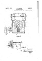
Other and further objects and advantages will appear from the following description taken in connection with the accompanying drawings, in which Fig. 1 is a side elevation of a portion of a locomotive showing the invention in posiprovision of tion thereon, with parts in section and parts broken away a Fig. 2 is a section on broken line 22 of Fig. 1; and
Fig, 3 is a detail plan view of the rear porshowing the clutch Onthe drawings the reference character 10 designates the firebox, 11 the grates thereof and 12 the back approved construction. The floor of the cab is shown at 1'3 and the deck of the tender at 14.
The back head 12 is provided with an open ing 15 through which coal is projected into the firebox by the stoker mechanism.
Since the details of the locomotive and tender form no part of the present invention,
the formof a the same is not illustrated and will not be further described.
The stoker comprises a housing 16 which is rigidly secure'dto and carried by the locomotive. The rear part of the housing is arranged to form theelevator casing 17 which is provided with rearward extension 18 above which is mounted a fuel distributor plate 190, the rear portion of which may take fuel receptacle 19. The fuel receptacle 19 is provided with an opening 20 in its bottom wall through Which'the fuel is deliveredby the elevator or plunger'21.
the usual manner.
head of a locomotive of any tion of which is in the form of atrough 23 located beneath the deck 14 of the tender for receiving coal from the same by gravity in The conduit 22 extends forwardly and upwardly, and its upper end is connected to the extension 18 of thecasing 17 and the fuel receptacle 19 by the universal joint as shown at 24. A suitable conveyor screw 25 isrotatably-mounted in the conduit 22 and conforms thereto. When, as shown,
'the conduit is curved or bent the conveyor screw is made sectional, the sections bein connected together by universal joints, as siown at 240. v I
Since the spacebetween the upper end of the conduit 22 and the bottom of the receptacle 19 is limited, it is desirable that means he provided for rendering the conveyor in operative except when the plunger 21 is in position to receive its load. Any suitable mechanism maybe provided for this purpose. Preferably means are provided for operating the screw 25 intermittently. The screw 25 is operated from the motor 26 through the worm 27 ,on the engine or power shaft 28, the worm Wheel 29, shaft 30, gears 31 and 32, the latter of which is loosely'mounted on the projecting end portion 33 of the screw shaft. Upon this shaft is mounted a clutch 34, comprising themovable clutch member 34a keyed on the shaft carried by the loosely mounted gear 32. The
Patent No. 1,809,903. As shown, this 33 and the clutch member 347) movable clutch member 34ais controlled by a lever 35, pivoted at '36 on a fixed support and having a pin 37 engaging a cam roove 38 formed in a collar 70. mounted onrt e'end of the shaft 30. This groove is so shaped'that it swings the lever to engage and disengage the clutch members 34a and 34b at each rotation of the shaft 3'0. The configuration given the groover38 will determme'the'period of action and rest of the screw, both as to duration and with relation to the movement of the other parts of the mechanism driven by the motor 26. I
It is desirable that means be provided for operating the plunger or elevator 21 rapidly during the time that the conveyor screw 25 is idle and for moving the same slowly while said screw is operating to supply fuel to the elevator casing. As shown, elliptic gears are employed for this purpose. The gears are operated'from the engine shaft 28 by means of a worm 39, see Fig. 2, which engages a worm wheel 40 mounted on the shaft 41. A gear 42 rigidly connected to the shaft 41 is ada ted to mesh with the gear 43 keyed to a sha 44 on which is mounted an elliptic gear 45. The elliptic gear 45 meshes with the corresponding elliptic gear 46 keyed to the crankshaft 47 on which is rigidly secured the crank 48, see Fig. 1, which in turn is connected to the plunger 21 by means of the link 49.
The parts are so constructed and arranged that when the plunger or elevator 21 has descended to the dotted line position shown at 50 the conveyor screw 25 will begin to operate and will continue to operate until the plunger 21 is elevated to the dotted line position 51 as shown in Fig. 1.
The elliptic gears 45, 46 may be so shaped as to give anv desired variation in the rate of movement of the plunger, and may be so positioned radially upon their shafts as to pro duce. such variations in any desired portion of the plunger stroke.
They are desirably shaped and positioned as shown, securing marked variation in the speed of the plunger, and causing it to move slowly during approximately the lower half of its cycle and rapidly during the upper half thereof.
Suitable means are provided for projecting the coal into the firebox in timed relation with the operation of the plunger 21. As shown, oscillating vanes 52 and 53 are employed for this purpose, and are arranged to be operated alternately, one of the vanes commencing its forward movement as the plunger approaches the upper limit of its stroke.
y appropriate means may be employed for operating the vanes. As shown, a cam member 54- provided with a cam groove 55 is rigidly mounted on the shaft 41. Lever members 56' and .57 pivotally mounted as'at 58 and 59are provided at their lower ends with cam engaging members or projections 60 and 61 which are adaptedto engage the cam groove 55 for oscillating the lever'members 56 and 57. The upper ends of the levers 56 and 57 are rovided with segmental gears 62 and 63 w ich engage gears 64 and mounted on the shafts 66 and 67 to whi thevanes 52 and 53 are rigidly secured.
' The cam 38 is configured to cause the screw to be driven while the p1un ger21 is passing through the lower portion of its cycle and to rest during the upper portion of such cycle, thus causing an advance of the fuel only when the plunger is in position to receive a load, insuring an adequate load and preventing congestion while the elevator is making its delivery.
I claim as'my invention 1. In a locomotive stoker, a fuel conveyor, a, reciprocating elevator, means for reciprocating said elevator, means for operating said conveyor for delivering fuel to said elevator, and means for rendering said last named means inoperativg-during the initial return Or lowering movement of said elevator.
2. In a locomotive Stoker, a pair of distributor vanes, means for operating the same,
means including a conveyor and continuous- 3. In combination, a locomotive firebox, an
opening in one .wall thereof, a distributor plate extending into said opening, an elevator-casing beneath said plate, a fuel conveyor, means for operating said'conveyor for delivering fuel to saidelevator casing, an ele-. Vator for delivering the'fuel from said casing onto said plate, oscillating vanes for moving the fuel on said plate into said firebox and means for rendering said conveyor operating means inoperative during the time the fuel is being projected into said firebox. v
4. In a locomotive st'oker, a fuel conveyor, a distributor plate, an elevator for receiving fuel from said conveyor and delivering the same to said plate,-a continuously operating powershaft, means for automatically intertermittently operating said conveyor from said shaft, and means for operating said elevator at a variable speed in timed relation to the operation of said conveyor, said means Causing said elevator to "move at its minimum speed during operation of said conveyor and to move at its maximum speed when said conveyor is at rest. 0
'5. In a. locomotive stoker, adistributor -member, an elevator for delivering fuel to said distributor member, a fuel conveyor,
means for driving saidconveyorintermibtently for delivering fuel intermittently to, said elevator, and means foroperating said elevator at a variable speed, said last named means causing said elevator to move at its maximum speed a .a time when said conveyor is not delivering -t ereto.
6. In a locomotive stoker, a fuel conveyor,
a reciprocating elevator, means for operat-- ing said conveyor for delivering fuel mter- Gil mittently to said elevator, and means for reciprocating said elevator at a greater average rate of speed when moving in one direchead communicating with ing, a unitary angular transfer condu1textion than when moving in the opposite direction.
7. In a locomotive stoker, a fuel conveyor, an elevator, means for operating said conveyor for delivering said elevator, means for operating said elevator at a variable speed, and means for rendering said conveyor operating means 1noperative while said elevator is at one extreme limit of its movement.
8. In a locomotive stoker, means for intermittently ejecting fuel, means for operating the same, means including a fuel conveyor and a continuously operated elevator receiving fuel from said conveyorfor delivering it into the'zone of action of said ejecting 'means for automatically intermittently rendriving means inoperdering said conveyor flow of fuel from said ative for stopping the conveyor into said casing ward movement and the initial downward movement of said plunger.
10. In a locomotive provided with a the box having a backhead with a firing opening therethrough and a tender having a floor, a fuel conveying system comprising a fuel discharge casing rigidly mounted on said backsaid firing opentending in a general forward and upward direction from a point below said tender floor to said fuel discharge casing and'flexibly connected to said discharge casing, said an gular transfer conduit having a posterior and an anterior bend, the portion of said conduit rearward of said posterior bendbeing disposed in a horizontal plane, the portion of said conduit between said posterior and said anterior bend inclined forwardly from said horizontal portion, at a slight angle from the horizontal, the portion of said conduit forward of said anterior bend inclined forwardlyfrom said second named portion, ata greater angle from the horizontal, a fuel conveyor screw within said transfer conduit composed of sections flexibly connected together adjacent said porterior and anterior bends, means for rotating said screw and means associatedewith said discharge casing for projecting fuel over the firebed in the firebox, the; fuel entering'the firebox through the firing opening. 3
11. In a locomotive fuel intermittently to forward portion sloping .upwar anelevator cas during the fina'l upfirebox, a fuel conveyor atits forward end terminating'on the provided with a as box having a backhead with a firing openingtherethrough and a tender having a cab deck for said locomotive rearward of the.
firebox, a fuel conveyor transferring fuel from the tender to the locomotive comprising a transfer conduit extending in a general forward and upward direction from apoint ber low said tender floor upwardly through the cab deck, to a point on the locomotive above such deck, said conduit comprising a substantially horizontal rearward portion disposed beneath the tender floor and at its forward end terminating at the front end of the tender, a slightly inclined intermediate portion extending upwardly and forwardly from the forward end of said rearward portion and at its forward end terminating on the locomotive beneath said deck, and an inclined dly and forwardly through said deck towards the rear Wall of the firebox from the forward end of the intermediate portion at a greater angle from the horizontal, said conduit portions belng in end to end. relation, a sectional screw in said transfer conduit comprising a screw section in each of said conduit portions,.said screw sections being jointed at the juncture of the intermediate conduit portion with the rear and forward conduit portions, .ineans to j for rotating said screw and means disposed at the forward end of the fuel conveyor arranged to receive the fuel therefrom and project it over the firebed in the firebox, the fuel entering the firebox through the firing opening.
12. In a box having a therethrough and a tender having a floor, a cab deck for said locomotive rearward of the transferring fuel from the tender to th locomotivecomprising a transfer conduit'extending in a general forward and-upward direction from a point below said' tenderfloor upwardly through the cab-deck, to a point on the. locomotive above such deck, said conduit comprising a sub-' stantially horizontal rearward portion disposed beneath the tender floor and at its for-' locomotive provided with a fireward end terminating at the front end of the tion extending upwardly and forwardly from the forwardend of said rearward portioni and 000- motive beneath said dec and an inclined forward portion throughout its length sloping upwardly and forwardly through said deck towards the rear wall of the firebox from the forwardend of the intermediate portion at a' greater angle from the horizontal, said conduit portions communicating at their adjacent ends and the intermediate and rearward conduit portions being rigidly related with respect to one another, a sectional screw in said transfer conduit comprising a screw section in each of two or more conduit portions, said screw sections being universally connected at their adjacent ends, means'for, rotating said screw and means disposed at A the forward end of the fuel conveyor arranged to receive the fuel therefrom and I pro ect it over the firebed in the firebox; the fuel entering the firebox through the firin openin o '13. 1%1 a locomotive provided with a firebox having a backhead with a firing opening therethrough and a tender having a floor, a
'ing a transfer conduit extending in a gencab deck for said locomotive rearward of the firebox, a fuel conveyor transferring. fuel from the tender to the locomotive compriseral forward and-upward direction from a point below said tender floor upwardly through the cab deck, to a point on the loco-' motive above such deck,'said conduit comprising a substantially horizontal rearward portion disposed beneath the tender floor and at its forward end terminating at the front end of the tender, a slightly inclined intermediate portion extending upwardly and forwardly from the forward end of said rearward portion and at its forward end terminating on the locomotive beneath said deck, and an inclined forward portion sloping upwardlyand forwardly through said deck to- Wards the rear wall of the firebox from the forward end of the intermediate portion at a greater angle from the horizontal, said conduit portions being in end to end relation and the intermediate and rearward conduit por tions being rigidly related with respect to one another, 'a sectional screw in said transfer' conduit comprising a screw section in each' of said conduit portions, said screw sections being jointed at the juncture of the intermediate conduit portion with the rear and foro ward conduit portions, means for rotating -sa1d screw and means disposed at the forward end of the fuel conveyor arranged to receive the fuel therefrom an'd,project it over the firebed in the firebox, the fuel entering the firebox through the firing openin v NATHAN M. Eownn.
Priority Applications (1)
| Application Number | Priority Date | Filing Date | Title |
|---|---|---|---|
| US89652A US1853692A (en) | 1926-02-20 | 1926-02-20 | Locomotive stoker |
Applications Claiming Priority (1)
| Application Number | Priority Date | Filing Date | Title |
|---|---|---|---|
| US89652A US1853692A (en) | 1926-02-20 | 1926-02-20 | Locomotive stoker |
Publications (1)
| Publication Number | Publication Date |
|---|---|
| US1853692A true US1853692A (en) | 1932-04-12 |
Family
ID=22218843
Family Applications (1)
| Application Number | Title | Priority Date | Filing Date |
|---|---|---|---|
| US89652A Expired - Lifetime US1853692A (en) | 1926-02-20 | 1926-02-20 | Locomotive stoker |
Country Status (1)
| Country | Link |
|---|---|
| US (1) | US1853692A (en) |
-
1926
- 1926-02-20 US US89652A patent/US1853692A/en not_active Expired - Lifetime
Similar Documents
| Publication | Publication Date | Title |
|---|---|---|
| US1853692A (en) | Locomotive stoker | |
| US1082419A (en) | Stoker. | |
| US1797871A (en) | Locomotive stoker | |
| US1796798A (en) | Locomotive stoker | |
| US1017170A (en) | Mechanical stoker. | |
| US1938551A (en) | Mechanical stoker | |
| US1519382A (en) | Underfeed stoker | |
| US1311917A (en) | Locomotive tender | |
| US1436870A (en) | Conveying apparatus for mechanical stokers | |
| US1851636A (en) | Locomotive stoker | |
| US2074300A (en) | Locomotive stoker | |
| US711668A (en) | Mechanical stoker. | |
| US770786A (en) | Firing locomotive-engines. | |
| US1897510A (en) | Locomotive stoker | |
| US2081276A (en) | Locomotive stoker | |
| US1850824A (en) | Locomotive stoker | |
| US2175161A (en) | Stoker | |
| US1312858A (en) | Of penn | |
| US1825135A (en) | Locomotive furnace | |
| US954500A (en) | Transfer mechanism. | |
| US1948686A (en) | Stoker mechanism | |
| US941698A (en) | Mechanical stoker for locomotives. | |
| US1452706A (en) | Furnace stoker | |
| US1856572A (en) | Stoker | |
| US1947724A (en) | Locomotive stoker |