US1856572A - Stoker - Google Patents
Stoker Download PDFInfo
- Publication number
- US1856572A US1856572A US87220A US8722026A US1856572A US 1856572 A US1856572 A US 1856572A US 87220 A US87220 A US 87220A US 8722026 A US8722026 A US 8722026A US 1856572 A US1856572 A US 1856572A
- Authority
- US
- United States
- Prior art keywords
- conveyer
- elevator
- screw
- fuel
- casing
- Prior art date
- Legal status (The legal status is an assumption and is not a legal conclusion. Google has not performed a legal analysis and makes no representation as to the accuracy of the status listed.)
- Expired - Lifetime
Links
- 239000000446 fuel Substances 0.000 description 20
- 230000003137 locomotive effect Effects 0.000 description 12
- 238000010276 construction Methods 0.000 description 3
- 230000010006 flight Effects 0.000 description 3
- 230000033001 locomotion Effects 0.000 description 2
- 238000009825 accumulation Methods 0.000 description 1
- 230000008878 coupling Effects 0.000 description 1
- 238000010168 coupling process Methods 0.000 description 1
- 238000005859 coupling reaction Methods 0.000 description 1
- 230000003028 elevating effect Effects 0.000 description 1
- 238000004519 manufacturing process Methods 0.000 description 1
- 230000002441 reversible effect Effects 0.000 description 1
Images

Classifications
-
- F—MECHANICAL ENGINEERING; LIGHTING; HEATING; WEAPONS; BLASTING
- F23—COMBUSTION APPARATUS; COMBUSTION PROCESSES
- F23K—FEEDING FUEL TO COMBUSTION APPARATUS
- F23K3/00—Feeding or distributing of lump or pulverulent fuel to combustion apparatus
- F23K3/04—Feeding or distributing of lump or pulverulent fuel to combustion apparatus for locomotive boiler furnaces
Definitions
- This invention relates to stokers, and more particularly to stoker mechanism for locomotiv'es.
- One of the objects of the invention is the provision of new and improved means for transferring fuel from the tender to the locomotive and delivering the same to the elevator mechanism.
- Another object of the invention is the provision of new and improved means for dividing the stream of fuel brought forward by the conveyer and delivering the same to the two elevator screws.
- a further object of the invention is the provision of new and improved Stoker mechanism for transferring fuel from the tender and delivering the same in an unbroken stream to each side of the firebox of the locomotive at points below the conventional firedoor opening.
- FIG. 1 is a side elevation of a portion of a locomotive and tender therefor showing the invention in osition thereon, with parts in section, parts roken away and parts omitted for the sake of clearness;
- Fig. 2 is a vertical section on line 2-2 of Fig. 1, with parts broken away;
- Fig. -3 is a rear elevation of a portion of a locomotive showing the invention in position thereon, with the conveyer in vertical section and with parts broken away;
- Fig. 4 is a section on line 4 4 of Fig. 3, with parts broken away.
- the reference character 10 designates a locomotive and 11 the tenderv therefor.
- the locomotive 10 is provided with the back wall 12 having the firedoor opening 13 leading to the firebox 14, as 1s usual in such constructions.
- This mechanism is provided for transferring fuel from the tender and distributing the same over the firebox.
- This mechanism comprises a conveyer casing 15 which 1s mounted in the usual manner beneath the deck of the tender, and two elevator casings 16 and 17.
- the conveyer casing 15 is preferably though not necessarily composed of two sections.
- veyer casing is provided on its forward end with a ball shaped extension which is adapted to engage in the rear end of the forward section of the conveyer casing 19.
- the rear portion of this section is in the form of a trough located beneath the tender for receivlng the fuel therefrom in the usual manner.
- the opening is slightly enlarged whereby the sections will be held assembled and at the same time will have a relative universal pivotal movement.
- the joint between the conveyer sections is arranged directly above or, as shown, adjacent to the coupling 3() between the locomotive and the tender, whereby in turning curves a minimum movement of the forward end of the rear section of the conveyer is necessary.
- a conveyer screw 22 is mounted in the casing 15. As shown, this screw, comprising'the rear section 23 and the forward section 24 connected together bythe universal joint 25 in the plane of the joint of the casing, is journaled in the latter as at 26.
- the section 24 of the screw is preferably though not necessarily provided with a double Hight 27 and 28 which will assist in equally distributing the fuel to the two elevators.
- the forward ends of the flights 27 and 28 may, if desired, be arranged radially of and in the plare of the axis of the screw, and at opposite sides thereof to form what may be termed paddles, as shown at 20 in Fig. 1. These paddles prevent the accumulation or jamming lof the fuel against the forward end of the conveyer by forcing the fuel lateralily through an opening at each side of the of the firedoor opening and at-each side thereof, and from which it is projected into the iirebox by blasts from the nozzles 33 in a manner well understood in the art.
- the passages in the upper ends of the casings 16 and 17 are curved as shown at 60, for directing the fuel forwardly into the distribu-v tor tubes 32 in front of the nozzles 33. The.
- the elbow or curved upper portion of the elevator is preferably provided with an opening 70 through which a bar may be inserted for loosening the fuel should the same become clogged in the elbow or -distributor tube.
- the casings 16 and 17 are' each composed of upper and lower sections 34 and 35, respectively. The lower end of the upper section telescopes into the upper end of the lower whereby the sections may be taken apart for inserting or removing the elevator screw. The sections are held assembled in any suitable manner, as by the set screws 36.
- the casings 16, 17 and 19 are so arranged that the flights of the screw section 24 are in close proximity to those of the elevator screws, the casing 19 being so constructed thatfthe fuel brought forward by the conveyer is delivered from a point between the ends of said conveyer directly to the flights of the elevator screws instead of delivering the same from the end of the conveyer into the elevator casings as is the usuali practice.
- the fuel is delivered to the elevator casings from each side of the conveyer screw.
- the parts are so arranged that the fuel Hows in a continuous stream through the conveyer and upward through each ele vator. v
- the casing 19 is only slightly larger in diameter than the conveyer screw, whereby the flow of the fuel along the conveyer is uniform and the proper division made for the two elevators.
- the casings 16 and 17 are inclined rearwardly from their upper to their lower ends whereby the fuel will readily pass in uniform streams from the conveyer upwardly therethrough.
- the inclination of the elevators is such that the three screws meet at or adjacent to the universal joint 1n the conveyer casing.
- the conveyer and elevator screws are all ⁇ operated from a common shaft 37 which in turn is operated either directly or through reduction gears from the crankshaft 38 of amotor 39.
- the motor may be of anytype, that shown being a four cylinder steam engine 41 having the intake and exhaust portsl 42 and 43, in common. F or the sake of clearness of illustration the piping is omitted.
- the engine is reversible in the usual manner. Since the details of the engine constitute no part of the present invention it is not thought necessary to illustrate or further describe the Same.
- the shaft 37 is mounted in a casing or bearing 44 which extends transversely of the v locomotive beneath the conveyer casing.
- the crank shaft 38 and adjacent end of the power shaft 37 are connected together through the sleeve 45.
- a plurality of sleeves 46 having worms thereon are mounted'on squared portions of the shaft 37 for rotating therewith for operating thev elevator screws 31 through the worm gears 48.
- a spacing sleeve 49 is mounted on the shaft 37 between the two worm gear sleeves 46. The worms on the sleeves 46 are threaded in opposite directions whereby the side thrust of one is counteracted by that of the other.
- a sleeve 51 having a worm thereon is rotatably mounted on the shaft 37. It is clutched to the shaft through a clutch sleeve 52, slidably but non-rotatably mounted thereon.
- the sleeve 52' is provided with clutch teeth 53 which are adapted to engage corresponding recesses 54 in the worm sleeve 51.
- the sleeve 54 is shifted by a shifter member 55 which is operated manually by, a lever 56, see I figs. ⁇
- a worm gear 57 rotated bythe worm on the sleeve 51 is adapted to operate .the conveyerscrew through the shaft 59 that extends to the rear of the conveyer.
- the shaft 59 is connected to the conveyer screw 22 through suitable gearing in the usual manner.
- the elevator screws When the parts are in the position shown in Fig. 2 and the motor is operated, the elevator screws will be operated and the conveyer screw will remain at rest. Since the motor may be reversed, the elevator screws may be operated in either direction without operating the conveyer screw.
- a transfer conduit in combination, a transfer conduit, a pair of elevator conduits each -having communication lwith the transfer conduit through a lateral opening, a transfer screw in the first named conduit, the forward end/ of which has a plurality of vanes each terminating opposite the lateral openings in a longitudinal and axially disposed extension, and a screw in each of the elevator conduits, such screws extending l respectively across the lateral openings whereby fuel is positively delivered from the transfer screw to the elevating screws.
- a transfer conduit in combination, a transfer conduit, a pair of elevator coni duits each having communication with the transfer'conduit through a lateral opening, a transfer screw in the transfer conduit, a screw in each of the elevator conduits, such screws extending respectively across the lateral openings, and means forming a part of the transfer screw for urging fuel laterally into the elevator conduits.
- a transfer conduit in combination, a transfer conduit, a pair of elevator conduits each communicating with the transfer conduit through a lateral opening, a transfer screw in the rst named conduit, a screw in eachof the elevator conduits and extending respectively across the lateral openings, and means forming a part of the transfer screw for urging fuel from the lower portion of the transfer conduit laterally into one of the elevator conduits, and for urging fuel from the upper portion of the transfer conduit into the other elevator conduit.
- a transfer conduit having a lateral delivery opening at its forward end portion at each side thereof, a pair of elevator conduits located one at each side of the transfer conduit and being open respectively to the delivery openings thereof, a conveying screw in the transfer conduit and extending across l the delivery openings thereof, the forward end of the screw having two vanes, the ends of which project parallel with the screw axis and are radially disposed.
Landscapes
- Engineering & Computer Science (AREA)
- Chemical & Material Sciences (AREA)
- Combustion & Propulsion (AREA)
- Mechanical Engineering (AREA)
- General Engineering & Computer Science (AREA)
- Screw Conveyors (AREA)
Description
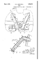
May 3, 1932. N. M. LOWER ET AL STOKER Original Filed Feb. l0, 1926 2 Sheets-Sheet and la 2 Edwz @er zrner mim. Y v
May 3, 1932 N. M. L owER E11-Al. '1,856,572
STOKER Original Filed Fab. 10, 1926 2 Sheets-Sheet 2 Pafemed May 3, 1932 UNITED STATES PATENT OFFICE NATHAN M. LOWm, F BALTIMORE, MARYLAND, AND EDWIN ARCHER TURNER, 0F NEW YORK, N. Y., ASSIGNORS, BY MESNE ASSIGNMENTS, TO THE STANDARD STOKEB COMPANY INC., 0F NEW YORK, N. Y., A CORPORATION OF DELAWARE STOXEB Application led February 10, 1926, Serial No. 87,220. Renewed March 21, 1931.
This invention relates to stokers, and more particularly to stoker mechanism for locomotiv'es.
One of the objects of the invention is the provision of new and improved means for transferring fuel from the tender to the locomotive and delivering the same to the elevator mechanism.
Another object of the invention is the provision of new and improved means for dividing the stream of fuel brought forward by the conveyer and delivering the same to the two elevator screws.
A further object of the invention is the provision of new and improved Stoker mechanism for transferring fuel from the tender and delivering the same in an unbroken stream to each side of the firebox of the locomotive at points below the conventional firedoor opening.
Other objects of the invention are the provision of new and improved stoker mechanism that is simple in construction, elcient in operation, cheap to manufacture, and that is not likely to become broken or get out of order.
Other and further objects and advantages of the invention will appear from the following description taken in connection with the accompanying drawings, in which Fig. 1 is a side elevation of a portion of a locomotive and tender therefor showing the invention in osition thereon, with parts in section, parts roken away and parts omitted for the sake of clearness;
Fig. 2 is a vertical section on line 2-2 of Fig. 1, with parts broken away;
Fig. -3 is a rear elevation of a portion of a locomotive showing the invention in position thereon, with the conveyer in vertical section and with parts broken away; and
Fig. 4 is a section on line 4 4 of Fig. 3, with parts broken away.
On the drawings, the reference character 10 designates a locomotive and 11 the tenderv therefor. The locomotive 10 is provided with the back wall 12 having the firedoor opening 13 leading to the firebox 14, as 1s usual in such constructions.
Stoker mechanism is provided for transferring fuel from the tender and distributing the same over the firebox. This mechanism comprises a conveyer casing 15 which 1s mounted in the usual manner beneath the deck of the tender, and two elevator casings 16 and 17. The conveyer casing 15 is preferably though not necessarily composed of two sections. veyer casing is provided on its forward end with a ball shaped extension which is adapted to engage in the rear end of the forward section of the conveyer casing 19. The rear portion of this section is in the form of a trough located beneath the tender for receivlng the fuel therefrom in the usual manner.
The rear' section 18 of the cont A pin 21 rigidly secured in the rear end of the front section of the conveyer casing engages in an opening in the lower portion of the rear section of the conveyer casing for preventing disengagement of the sections of the casing. The opening is slightly enlarged whereby the sections will be held assembled and at the same time will have a relative universal pivotal movement. The joint between the conveyer sections is arranged directly above or, as shown, adjacent to the coupling 3() between the locomotive and the tender, whereby in turning curves a minimum movement of the forward end of the rear section of the conveyer is necessary.
A conveyer screw 22 is mounted in the casing 15. As shown, this screw, comprising'the rear section 23 and the forward section 24 connected together bythe universal joint 25 in the plane of the joint of the casing, is journaled in the latter as at 26.
The section 24 of the screw is preferably though not necessarily provided with a double Hight 27 and 28 which will assist in equally distributing the fuel to the two elevators. The forward ends of the flights 27 and 28 may, if desired, be arranged radially of and in the plare of the axis of the screw, and at opposite sides thereof to form what may be termed paddles, as shown at 20 in Fig. 1. These paddles prevent the accumulation or jamming lof the fuel against the forward end of the conveyer by forcing the fuel lateralily through an opening at each side of the of the firedoor opening and at-each side thereof, and from which it is projected into the iirebox by blasts from the nozzles 33 in a manner well understood in the art. The passages in the upper ends of the casings 16 and 17 are curved as shown at 60, for directing the fuel forwardly into the distribu-v tor tubes 32 in front of the nozzles 33. The.
upper ends 'of the elevator screws are floating-that is, they are not provided with journals, hence the fuel is unobstructed in its flow from the elevator into the distributor tube. The elbow or curved upper portion of the elevator is preferably provided with an opening 70 through which a bar may be inserted for loosening the fuel should the same become clogged in the elbow or -distributor tube. The casings 16 and 17 are' each composed of upper and lower sections 34 and 35, respectively. The lower end of the upper section telescopes into the upper end of the lower whereby the sections may be taken apart for inserting or removing the elevator screw. The sections are held assembled in any suitable manner, as by the set screws 36.
The casings 16, 17 and 19 are so arranged that the flights of the screw section 24 are in close proximity to those of the elevator screws, the casing 19 being so constructed thatfthe fuel brought forward by the conveyer is delivered from a point between the ends of said conveyer directly to the flights of the elevator screws instead of delivering the same from the end of the conveyer into the elevator casings as is the usuali practice. As shown, the fuel is delivered to the elevator casings from each side of the conveyer screw. The parts are so arranged that the fuel Hows in a continuous stream through the conveyer and upward through each ele vator. v
In the present construction the casing 19 is only slightly larger in diameter than the conveyer screw, whereby the flow of the fuel along the conveyer is uniform and the proper division made for the two elevators. The casings 16 and 17 are inclined rearwardly from their upper to their lower ends whereby the fuel will readily pass in uniform streams from the conveyer upwardly therethrough. Preferably, though not necessarily, the inclination of the elevators is such that the three screws meet at or adjacent to the universal joint 1n the conveyer casing.
The conveyer and elevator screws are all` operated from a common shaft 37 which in turn is operated either directly or through reduction gears from the crankshaft 38 of amotor 39. The motor may be of anytype, that shown being a four cylinder steam engine 41 having the intake and exhaust portsl 42 and 43, in common. F or the sake of clearness of illustration the piping is omitted. The engine is reversible in the usual manner. Since the details of the engine constitute no part of the present invention it is not thought necessary to illustrate or further describe the Same.
The shaft 37 is mounted in a casing or bearing 44 which extends transversely of the v locomotive beneath the conveyer casing. The crank shaft 38 and adjacent end of the power shaft 37 are connected together through the sleeve 45. A plurality of sleeves 46 having worms thereon are mounted'on squared portions of the shaft 37 for rotating therewith for operating thev elevator screws 31 through the worm gears 48. A spacing sleeve 49 is mounted on the shaft 37 between the two worm gear sleeves 46. The worms on the sleeves 46 are threaded in opposite directions whereby the side thrust of one is counteracted by that of the other.
Suitable means are provided for operating the conveyer screw from the shaft 37 and for operating the elevator screws independently of the conveyer screw. As shown, a sleeve 51 having a worm thereon is rotatably mounted on the shaft 37. It is clutched to the shaft through a clutch sleeve 52, slidably but non-rotatably mounted thereon. The sleeve 52'is provided with clutch teeth 53 which are adapted to engage corresponding recesses 54 in the worm sleeve 51. The sleeve 54 is shifted by a shifter member 55 which is operated manually by, a lever 56, see I figs.`
2 and 3. A worm gear 57 rotated bythe worm on the sleeve 51 is adapted to operate .the conveyerscrew through the shaft 59 that extends to the rear of the conveyer. The shaft 59 is connected to the conveyer screw 22 through suitable gearing in the usual manner.
When the parts are in the position shown in Fig. 2 and the motor is operated, the elevator screws will be operated and the conveyer screw will remain at rest. Since the motor may be reversed, the elevator screws may be operated in either direction without operating the conveyer screw.
We claim as our, invention:
1. In a locomotive Stoker, in combination, a transfer conduit, a pair of elevator conduits each -having communication lwith the transfer conduit through a lateral opening, a transfer screw in the first named conduit, the forward end/ of which has a plurality of vanes each terminating opposite the lateral openings in a longitudinal and axially disposed extension, and a screw in each of the elevator conduits, such screws extending l respectively across the lateral openings whereby fuel is positively delivered from the transfer screw to the elevating screws.
2. In a locomotive Stoker, in combination, a transfer conduit, a pair of elevator coni duits each having communication with the transfer'conduit through a lateral opening, a transfer screw in the transfer conduit, a screw in each of the elevator conduits, such screws extending respectively across the lateral openings, and means forming a part of the transfer screw for urging fuel laterally into the elevator conduits.
3. In a locomotive Stoker, in combination, a transfer conduit, a pair of elevator conduits each communicating with the transfer conduit through a lateral opening, a transfer screw in the rst named conduit, a screw in eachof the elevator conduits and extending respectively across the lateral openings, and means forming a part of the transfer screw for urging fuel from the lower portion of the transfer conduit laterally into one of the elevator conduits, and for urging fuel from the upper portion of the transfer conduit into the other elevator conduit.
4:. In a locomotive Stoker, in combination, a transfer conduit having a lateral delivery opening at its forward end portion at each side thereof, a pair of elevator conduits located one at each side of the transfer conduit and being open respectively to the delivery openings thereof, a conveying screw in the transfer conduit and extending across l the delivery openings thereof, the forward end of the screw having two vanes, the ends of which project parallel with the screw axis and are radially disposed.
In testimony whereof we affix our signatures. NATHAN M. LOWER.
EDWIN ARCHER TURNER.
Priority Applications (1)
| Application Number | Priority Date | Filing Date | Title |
|---|---|---|---|
| US87220A US1856572A (en) | 1926-02-10 | 1926-02-10 | Stoker |
Applications Claiming Priority (1)
| Application Number | Priority Date | Filing Date | Title |
|---|---|---|---|
| US87220A US1856572A (en) | 1926-02-10 | 1926-02-10 | Stoker |
Publications (1)
| Publication Number | Publication Date |
|---|---|
| US1856572A true US1856572A (en) | 1932-05-03 |
Family
ID=22203817
Family Applications (1)
| Application Number | Title | Priority Date | Filing Date |
|---|---|---|---|
| US87220A Expired - Lifetime US1856572A (en) | 1926-02-10 | 1926-02-10 | Stoker |
Country Status (1)
| Country | Link |
|---|---|
| US (1) | US1856572A (en) |
Cited By (1)
| Publication number | Priority date | Publication date | Assignee | Title |
|---|---|---|---|---|
| US2691455A (en) * | 1949-04-08 | 1954-10-12 | Babcock & Wilcox Co | Locomotive tender with material handling equipment |
-
1926
- 1926-02-10 US US87220A patent/US1856572A/en not_active Expired - Lifetime
Cited By (1)
| Publication number | Priority date | Publication date | Assignee | Title |
|---|---|---|---|---|
| US2691455A (en) * | 1949-04-08 | 1954-10-12 | Babcock & Wilcox Co | Locomotive tender with material handling equipment |
Similar Documents
| Publication | Publication Date | Title |
|---|---|---|
| US1856572A (en) | Stoker | |
| US2195815A (en) | Crushing conveyer for locomotive stokers | |
| US1757580A (en) | Inside feed stoker | |
| US1797871A (en) | Locomotive stoker | |
| US1948686A (en) | Stoker mechanism | |
| US2569812A (en) | Tender conveyer system for locomotive stokers | |
| US1833327A (en) | Stoker mechanism | |
| US2131907A (en) | Conveying mechanism | |
| US2059705A (en) | Stoker conveyer | |
| US1916177A (en) | Stoker mechanism | |
| US2075352A (en) | Driving mechanism | |
| US2029296A (en) | Multiple underfeed stoker | |
| US2074300A (en) | Locomotive stoker | |
| US2115517A (en) | Drive mechanism | |
| US1952691A (en) | Locomotive stoker | |
| US2061783A (en) | Stoker mechanism | |
| US1863289A (en) | Locomotive stoker | |
| US1497014A (en) | Automatic stoker | |
| US2022993A (en) | Stoker mechanism | |
| US1082419A (en) | Stoker. | |
| US1885203A (en) | Mechanical stoker | |
| US1953021A (en) | Stoker | |
| US2029519A (en) | Stoker | |
| US2074301A (en) | Locomotive stoker | |
| US2015526A (en) | Stoker |