US1853645A - Joist - Google Patents
Joist Download PDFInfo
- Publication number
- US1853645A US1853645A US423488A US42343830A US1853645A US 1853645 A US1853645 A US 1853645A US 423488 A US423488 A US 423488A US 42343830 A US42343830 A US 42343830A US 1853645 A US1853645 A US 1853645A
- Authority
- US
- United States
- Prior art keywords
- sections
- chords
- section
- chord
- joist
- Prior art date
- Legal status (The legal status is an assumption and is not a legal conclusion. Google has not performed a legal analysis and makes no representation as to the accuracy of the status listed.)
- Expired - Lifetime
Links
- 239000000543 intermediate Substances 0.000 description 21
- 229910000746 Structural steel Inorganic materials 0.000 description 9
- 238000010276 construction Methods 0.000 description 6
- 230000006835 compression Effects 0.000 description 4
- 238000007906 compression Methods 0.000 description 4
- 239000007787 solid Substances 0.000 description 2
- CZTQRSPXKRZGAN-UHFFFAOYSA-N 2-chloro-n-(2,6-diethylphenyl)-n-(2-propoxyethyl)acetamide;4,6-dichloro-2-phenylpyrimidine Chemical compound ClC1=CC(Cl)=NC(C=2C=CC=CC=2)=N1.CCCOCCN(C(=O)CCl)C1=C(CC)C=CC=C1CC CZTQRSPXKRZGAN-UHFFFAOYSA-N 0.000 description 1
- 241000182988 Assa Species 0.000 description 1
- 229910000831 Steel Inorganic materials 0.000 description 1
- 238000005452 bending Methods 0.000 description 1
- 238000009435 building construction Methods 0.000 description 1
- 230000000694 effects Effects 0.000 description 1
- 238000004519 manufacturing process Methods 0.000 description 1
- 239000000463 material Substances 0.000 description 1
- 239000002184 metal Substances 0.000 description 1
- 229910052751 metal Inorganic materials 0.000 description 1
- 238000000034 method Methods 0.000 description 1
- 238000010008 shearing Methods 0.000 description 1
- 239000010959 steel Substances 0.000 description 1
- 238000003860 storage Methods 0.000 description 1
- 239000013589 supplement Substances 0.000 description 1
- 238000003466 welding Methods 0.000 description 1
Images
Classifications
-
- E—FIXED CONSTRUCTIONS
- E04—BUILDING
- E04G—SCAFFOLDING; FORMS; SHUTTERING; BUILDING IMPLEMENTS OR AIDS, OR THEIR USE; HANDLING BUILDING MATERIALS ON THE SITE; REPAIRING, BREAKING-UP OR OTHER WORK ON EXISTING BUILDINGS
- E04G11/00—Forms, shutterings, or falsework for making walls, floors, ceilings, or roofs
- E04G11/36—Forms, shutterings, or falsework for making walls, floors, ceilings, or roofs for floors, ceilings, or roofs of plane or curved surfaces end formpanels for floor shutterings
- E04G11/48—Supporting structures for shutterings or frames for floors or roofs
- E04G11/50—Girders, beams, or the like as supporting members for forms
- E04G11/52—Girders, beams, or the like as supporting members for forms of several units arranged one after another
Definitions
- Patented Apr. 12, 193 2 are assa RUSSELL W. STAMBAUGH AND WALTER E. BROWNE, 0F MILWAUKEE, WISCONSIN, AS-
- This invention relates to certain new and useful improvements in joists and refers more particularly to truss joists for supporting concrete forms during the construction of buildings and the like.-
- Another object of this invention is to provide novel means for adjusting the length of the joist without detracting from its strength to readily adapt it for universal use.
- a more specific object of this invention resides in the provision of intermediate and end sections, the intermediate sections being of diderent lengths and being readily connected with each other and with the end sections to enable joisrs to be built up in any desired lengths.
- a further object of this invention resides in the provision of means for adjusting the supporting portion of the end sections to protwo' feet apart yide finer adjustment of the length of the joists.
- a still further object of this invention resides in the provision of means whereby the support for the pans or forms may bequickly removed at any time without disturbing the joists, thus permitting the same to support the floor after it has set.
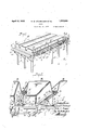
- Figure l isa perspective view illustrating a typical building construction, and the manner of using the joists of this invention.
- Figure 2 is an enlarged, fragmentary perspective view illustrating the manner of supporting the joists from the beam supports and the. manner in which the joists support the concrete forms;
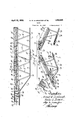
- Figure 3 is a side elevational view with parts broken away and in section to illustrate structural details, of one end of a joist constrjlicted in accordance with this invention, an
- Figure 4 is a perspective view of an end sec- 1 described.
- the intermediate sections 13 are constructed in different lengths and thus permit joists to be built up for all practical spans, by connecting intermediate sections of the desired lengths between pairs of end sections.
- top and bottom chords 14 and 15 are maintained in parallel spaced relation by a plurality of diagonal braces-or struts 16 which absorbs shearing stretches and are preferably formed by bending a single length of round bar stock and welding the same to the top and bottom chords, as at 17, and 18, respectively.
- top chord 1a is a compressible member in each instance it is preferably channel shaped in cross section to provide the necessary rigidity and the bottom chord, which is subjected only to tension stresses, may be of flat bar stock or any other desired cross sectional shape.
- the end sections differ from the interme diate sections in that their outer ends are adapted toengage suitable supports at their upper portlons, and to this effect the bottom chord 15 has its outer end directed diagonally upwardly toward the top chord, as at 19, to be welded or otherwise secured to a trans verse plate 20.
- the plate 20 extends across and is adj ustably connected-with the horizontal flanges of a pair of angle iron members 21 by bolts 22, and the vertical flanges of the angle iron members are adjustably connected with the flanges of the adjacent end portion of the top chord 14 by bolts 23, so that the angle iron members 21 are adjustable to wardand away from the end section proper and thus providing an additional means of adjusting the overall length of the joists.
- the spacing of the holes in the flanges of the angle iron members through which the bolts 22 and 23 pass and of the holes in the flanges of the top chord are such that the angle iron members may be moved toward and from the end sections in steps of approximately two inches, and for a total distance of approximately six inches
- the two end sections of a joist thus provide about a twelve inch range of adjustment which supplement the adjustment aflorded by the different len hs of the intermediate sections and rea ily permits the overall span of the joists to be adjusted in units of lengths'less than the length of the shortest section to accommodate the distance between the supports.
- connection between the end sections and the intermediate sections includes, at the top, gusset plates 24 welded or otherwise secured to the inner surface of the end section top chord channel web, and which is receivable between the inner surface of the web of the adjacent end of the intermediate section top chord and a channel iron member 25 welded or otherwise secured to the adjacent end portion of the intermediate section top chord.
- gusset plates 24 welded or otherwise secured to the inner surface of the end section top chord channel web, and which is receivable between the inner surface of the web of the adjacent end of the intermediate section top chord and a channel iron member 25 welded or otherwise secured to the adjacent end portion of the intermediate section top chord.
- the sections are connected by pairs of spaced gusset plates 27 welded or otherwise secured to .the end-of the intermediate section bottom chord and between which the adjacent end of the end section bottom chord is receivable.
- Aligned apertures 28 in the gusset plates 27 and the adj a cent end portion of the end section bottom chord are adapted to receive bolts 29 which securely connect the bottom chords of the two sections against tension stresses,
- the diagonal braces or struts 16 of the sections have their adjacent ends threaded, as at 30, and are connected by an elongated nut 31 which, when the sections are separated may be carried by either section.
- Wooden nailing strips 33 are bolted, as at 34, to the upper surface of the top chords of the end and intermediate sections and are of a width substantially equal to the width of the channel member forming the top chords, to provide nailing strips for solid decking.
- solid decking is not employed and the joists are therefore also equipped with side nailing strips 35 which, as best illustrated in Figures 2 and 4, are secured to the sides of the top strips 33 by double headednails 36. The strips extend beyond the normal width of the joist and provide means for supporting the pans 32, as clearly illustrated in Figure 2.
- the forms may be removed at any time without disturbing the joists, which remaln to support the concrete until it has thoroughly dried, by merely removing the side strlps by drawing out the double headed nails 36.
- the strips 33 and 35 are not extended to the very ends of the angle iron members 21 and the space thereabove is adapted to be closed by a hood 37 which, as best illustrated in Figure 4, has a top 38 and sides 39, to respectively form continuations of the top of the strip 33 and the outer sides of the strips 35 when in position'.
- U shaped clips 40 riveted or otherwise secured to the top portion 38 are snugly engageable over the outer faces of the vertical flanges of the angle iron members to secure the hood in position.
- a joist structure of the character described comprising, a plurality of sections, each section having a top and a bottom chord, diagonal braces connecting said top and bottom chords, means for readily detachabl-y connectingadjacent end portions of the top and bottom chords and means for readily detachably' connecting adjacent end portions of the diagonal braces of adjacent sections at points intermediate said top and bottomchords.
- a joist-structure adapted to span the distance between two supports comprising, a rigid intermediate section having an upper andlower chord, diagonal braces connecting said upper and lower chord to hold the chords in spaced parallel relationship, a pair of end sections attached to the opposite ends respectively of said intermediate section, said end sections each having an u per and a lower chord detachably connecte to the upper and lower chords of said intermediate section, diagonal braces between the upper and lower chords of said end sections and means connecting said diagonal braces and said end sections with the diagonal braces of said intermediate section intermediate said chords.
- an intermediate section having spaced top and bottom chords, diagonal braces connecting the top and bottom chords, a pair of end sections having top and bottom chords forming a continuance of the top and bottom chords respectively of said intermediatesection, diagonal braces between the top and bottom chord of said end sections, means 5.
- a joist structure of the character de-..
- a joist structure of the'character described comprising separable sections including top and bottom chords diagonal braces maintaining said top and bottom chords in spaced relation the outermost braces terminating intermediate said chords, means for readily detachably connectingv the sections and including a nut member threadedly engageable with the acent ends of the diagonal braces.
- a joist structure adapted to span a distance between two supports for supporting concrete forms or the like comprising, a plurality of sections detachably connected end to end, each section having an upper and lower chord and means connected to both upper and lower chords of one of said sections for readily adjusting the length of the joist structure in units of length less than the length of the shortest section to accommodate the distance between the supports.
- a joist comprising a plurality of sections, means for varying the overall length of the joist,each section including spaced top and bottom chords, and a plurality of diagonal braces extending therebetween, the end braces of each section being free with respect to one of the chords, and means for connecting the ends of said sections with the free ends 61? said braces brought into continuous bridging relation with respect to the chords.
- a joist structure adapted to span a distance between two supports for supporting concrete forms or the like comprising, a plurality of sections each formed of a compression chord and 'a tension chord connected by a separate diagonal brace forming a zig-zag support throughout the length of the section,
- each brace having free end terminals, means for detachably connecting the adjacent ends of the compression and tension chordsiof each section, and means for associating the adjacent free end terminals of the diagonal braces to continue the zig-zag support throughout the length of the assembly.
- a joist structure adapted to span a distance between two supports for supporting concrete forms or the like comprising, a plurality of sections each formed of a compression chord and a tension chord connected by a separate diagonal brace forming a zig-zag support throughout the length of the section, each brace having free end terminals, means for detachably connecting the adjacent ends of the compression and tension chords of each section, means for associatinig the adjacent free end terminals of the diagonal braces to continue the zig-zag support throughout the length of' the assembly, and means to adjust the overall length of the joist assembly in units of length less than the length of any one section.
Landscapes
- Engineering & Computer Science (AREA)
- Architecture (AREA)
- Mechanical Engineering (AREA)
- Civil Engineering (AREA)
- Structural Engineering (AREA)
- Floor Finish (AREA)
Description
Patented Apr. 12, 193 2 are assa RUSSELL W. STAMBAUGH AND WALTER E. BROWNE, 0F MILWAUKEE, WISCONSIN, AS-
SIGNORS TO PORATION OF WISCONSIN ADJUSTABLE JOIST COMPANY, OF MILWAUKEE, WISCONSIN, A CUB! JOIST Application filed January 25,, 1980. Serial No. 423,438a
This invention relates to certain new and useful improvements in joists and refers more particularly to truss joists for supporting concrete forms during the construction of buildings and the like.-
Heretofore it has been customary to sup-.
sofit boards upon which the metal port the forms are placed by vertical shorpans or ing spaced approximatel I along the entire length 0 the boards, and as the distance between adjacent lines of shoring, which is governed bythe width of the pans, was also about the same the entire floor space beneath the floor iii-progress was practically filled with vertical shoring.
This condition is obviously objectionable especially during cold weather and it is, therefore, one of the objects of this invention to provide an efiicient joist which will adequately support the concrete forms and the pouredfloor independent of vertical shoring along its length, thus permitting the space below the floor in progress to 'be-used for the storage of materials or as a working space for the various trades. With the present system of prop supporting the floor forms, it is ossible to make up only one floor at a time and to pour that floor and allow the concrete to set beforestarting-work on the next fioor.
It is an object of the present invention to provide a method whereby the floor forms are supported from the structural steel and thus enable a plurality of floors to be made up either previous to the pouring of the lowor 'fioors, or while the pouring is in progress.
Another object of this invention is to provide novel means for adjusting the length of the joist without detracting from its strength to readily adapt it for universal use.
A more specific object of this invention resides in the provision of intermediate and end sections, the intermediate sections being of diderent lengths and being readily connected with each other and with the end sections to enable joisrs to be built up in any desired lengths. 4
A further object of this invention resides in the provision of means for adjusting the supporting portion of the end sections to protwo' feet apart yide finer adjustment of the length of the joists.
And a still further object of this invention resides in the provision of means whereby the support for the pans or forms may bequickly removed at any time without disturbing the joists, thus permitting the same to support the floor after it has set.
With the above and other objects in view which will appear as the. description proceeds, our invention resides in the novel construction, combination and arrangement of parts substantially as hereinafter described and more particularly defined bythe appended claims, it being understood that such changes in the precise embodiment of the hereindisclosed invention ma be made as come Within the scope of the claims.
In the accompanying drawings, we have illustrated one complete example of the physical embodiment of our invention constructed accordin to the best mode we have so far devised or the practical application of the principles thereof, and in which:
Figure l isa perspective view illustrating a typical building construction, and the manner of using the joists of this invention;
Figure 2 is an enlarged, fragmentary perspective view illustrating the manner of supporting the joists from the beam supports and the. manner in which the joists support the concrete forms;
Figure 3 is a side elevational view with parts broken away and in section to illustrate structural details, of one end of a joist constrjlicted in accordance with this invention, an
Ell
Figure 4 is a perspective view of an end sec- 1 described. The intermediate sections 13 are constructed in different lengths and thus permit joists to be built up for all practical spans, by connecting intermediate sections of the desired lengths between pairs of end sections.
The specific construction of the joists is the same throughout their entire length and includes top and bottom chords 14 and 15, respectively, maintained in parallel spaced relation by a plurality of diagonal braces-or struts 16 which absorbs shearing stretches and are preferably formed by bending a single length of round bar stock and welding the same to the top and bottom chords, as at 17, and 18, respectively. Since the top chord 1a is a compressible member in each instance it is preferably channel shaped in cross section to provide the necessary rigidity and the bottom chord, which is subjected only to tension stresses, may be of flat bar stock or any other desired cross sectional shape.
The end sections differ from the interme diate sections in that their outer ends are adapted toengage suitable supports at their upper portlons, and to this effect the bottom chord 15 has its outer end directed diagonally upwardly toward the top chord, as at 19, to be welded or otherwise secured to a trans verse plate 20.The plate 20 extends across and is adj ustably connected-with the horizontal flanges of a pair of angle iron members 21 by bolts 22, and the vertical flanges of the angle iron members are adjustably connected with the flanges of the adjacent end portion of the top chord 14 by bolts 23, so that the angle iron members 21 are adjustable to wardand away from the end section proper and thus providing an additional means of adjusting the overall length of the joists.
The spacing of the holes in the flanges of the angle iron members through which the bolts 22 and 23 pass and of the holes in the flanges of the top chord are such that the angle iron members may be moved toward and from the end sections in steps of approximately two inches, and for a total distance of approximately six inches The two end sections of a joist thus provide about a twelve inch range of adjustment which supplement the adjustment aflorded by the different len hs of the intermediate sections and rea ily permits the overall span of the joists to be adjusted in units of lengths'less than the length of the shortest section to accommodate the distance between the supports.
I The connection between the end sections and the intermediate sections includes, at the top, gusset plates 24 welded or otherwise secured to the inner surface of the end section top chord channel web, and which is receivable between the inner surface of the web of the adjacent end of the intermediate section top chord and a channel iron member 25 welded or otherwise secured to the adjacent end portion of the intermediate section top chord. When so engaged the adjacent ends of the top chords of the end and intermediate sections abut to impart stresses directly to each other. A bolt 26 passed through aligned aperturesl in the end section top chord, the gusset plate 24, and the channel 25 prevents accidental disengagement, but is not essential.
At the bottom, the sectionsare connected by pairs of spaced gusset plates 27 welded or otherwise secured to .the end-of the intermediate section bottom chord and between which the adjacent end of the end section bottom chord is receivable. Aligned apertures 28 in the gusset plates 27 and the adj a cent end portion of the end section bottom chord are adapted to receive bolts 29 which securely connect the bottom chords of the two sections against tension stresses,
The diagonal braces or struts 16 of the sections have their adjacent ends threaded, as at 30, and are connected by an elongated nut 31 which, when the sections are separated may be carried by either section.
This manner of connecting the sections obtains throughout the entire structure so that theparts are readily interchangeable and permit quick addition or removal of sections to adapt the joists to any desired particular span.
With the joists built up to the desired length, they are placed in position with their ends supported upon the boards 10, as illustrated in Figures 1 and 2 and spaced accord ing to the width of the pans 32 which are sup ported by the joists in the following manner:
With the pans supported in this manner the forms may be removed at any time without disturbing the joists, which remaln to support the concrete until it has thoroughly dried, by merely removing the side strlps by drawing out the double headed nails 36.
In view of the adjustable feature of the and sections, the strips 33 and 35 are not extended to the very ends of the angle iron members 21 and the space thereabove is adapted to be closed by a hood 37 which, as best illustrated in Figure 4, has a top 38 and sides 39, to respectively form continuations of the top of the strip 33 and the outer sides of the strips 35 when in position'.. U shaped clips 40 riveted or otherwise secured to the top portion 38 are snugly engageable over the outer faces of the vertical flanges of the angle iron members to secure the hood in position.
From the foregoing description taken in connection with the accompanying drawings, it will be readily apparent to those skilled in the art'to which an invention of the character described appertains, that we provide a novel construction for joists whichlends itself particularly'well to use as a support for concrete forms without the use of vertical shoring to thus provide a useable space below the floor-in progress, and-whereby in steel skeleton construction anyfloor may be poured without waiting for the ordinary progress of the work. It is also apparentthatthe joists of this invention can be shipped and stored in lengths convenient for handling and that they may also be used as a permanent support for floors and when so used, permits their manufacture in regular commercial-mill lengths which may be cut at any point and attached to the adjustable end sections to provide any desired length.
What we claim as our invention is:
1. A joist structure of the character described comprising, a plurality of sections, each section having a top and a bottom chord, diagonal braces connecting said top and bottom chords, means for readily detachabl-y connectingadjacent end portions of the top and bottom chords and means for readily detachably' connecting adjacent end portions of the diagonal braces of adjacent sections at points intermediate said top and bottomchords.
2. In a joist-structure adapted to span the distance between two supports comprising, a rigid intermediate section having an upper andlower chord, diagonal braces connecting said upper and lower chord to hold the chords in spaced parallel relationship, a pair of end sections attached to the opposite ends respectively of said intermediate section, said end sections each having an u per and a lower chord detachably connecte to the upper and lower chords of said intermediate section, diagonal braces between the upper and lower chords of said end sections and means connecting said diagonal braces and said end sections with the diagonal braces of said intermediate section intermediate said chords.
3. In a joist structure of the character described, an intermediate section having spaced top and bottom chords, diagonal braces connecting the top and bottom chords, a pair of end sections having top and bottom chords forming a continuance of the top and bottom chords respectively of said intermediatesection, diagonal braces between the top and bottom chord of said end sections, means 5. A joist structure of the character de-..
scribed, comprising separable sections each having top and bottom chords diagonal braces maintaining said. chords in spaced relation, means for readily detachably connecting the adjacent ends of the sections, said means including a member carried by one of the diagonal braces oi one section readily en- 'vgageable with anadjacent portion of one of the diagonal braces of the other section intermediate said chords.
6. A joist structure of the'character described, comprising separable sections including top and bottom chords diagonal braces maintaining said top and bottom chords in spaced relation the outermost braces terminating intermediate said chords, means for readily detachably connectingv the sections and including a nut member threadedly engageable with the acent ends of the diagonal braces.
7. A joist structure adapted to span a distance between two supports for supporting concrete forms or the like comprising, a plurality of sections detachably connected end to end, each section having an upper and lower chord and means connected to both upper and lower chords of one of said sections for readily adjusting the length of the joist structure in units of length less than the length of the shortest section to accommodate the distance between the supports. j
8; A joist comprising a plurality of sections, means for varying the overall length of the joist,each section including spaced top and bottom chords, and a plurality of diagonal braces extending therebetween, the end braces of each section being free with respect to one of the chords, and means for connecting the ends of said sections with the free ends 61? said braces brought into continuous bridging relation with respect to the chords.
I -9. A joist structure adapted to span a distance between two supports for supporting concrete forms or the like comprising, a plurality of sections each formed of a compression chord and 'a tension chord connected by a separate diagonal brace forming a zig-zag support throughout the length of the section,
each brace having free end terminals, means for detachably connecting the adjacent ends of the compression and tension chordsiof each section, and means for associating the adjacent free end terminals of the diagonal braces to continue the zig-zag support throughout the length of the assembly.
10. A joist structure adapted to span a distance between two supports for supporting concrete forms or the like comprising, a plurality of sections each formed of a compression chord and a tension chord connected by a separate diagonal brace forming a zig-zag support throughout the length of the section, each brace having free end terminals, means for detachably connecting the adjacent ends of the compression and tension chords of each section, means for associatinig the adjacent free end terminals of the diagonal braces to continue the zig-zag support throughout the length of' the assembly, and means to adjust the overall length of the joist assembly in units of length less than the length of any one section.- I
In testimony whereof, We have hereunto affixed our signatures.
RUSSELL W. STAMBAUGH. WALTER E. BROWNE;
Priority Applications (1)
| Application Number | Priority Date | Filing Date | Title |
|---|---|---|---|
| US423488A US1853645A (en) | 1930-01-25 | 1930-01-25 | Joist |
Applications Claiming Priority (1)
| Application Number | Priority Date | Filing Date | Title |
|---|---|---|---|
| US423488A US1853645A (en) | 1930-01-25 | 1930-01-25 | Joist |
Publications (1)
| Publication Number | Publication Date |
|---|---|
| US1853645A true US1853645A (en) | 1932-04-12 |
Family
ID=23678906
Family Applications (1)
| Application Number | Title | Priority Date | Filing Date |
|---|---|---|---|
| US423488A Expired - Lifetime US1853645A (en) | 1930-01-25 | 1930-01-25 | Joist |
Country Status (1)
| Country | Link |
|---|---|
| US (1) | US1853645A (en) |
Cited By (4)
| Publication number | Priority date | Publication date | Assignee | Title |
|---|---|---|---|---|
| DE921283C (en) * | 1948-10-02 | 1954-12-13 | Adolf Dr-Ing Koch | Construction element, in particular made of reinforced concrete, or auxiliary construction element made of another material with a joint that is resistant to bending, shear and torsion |
| US2793720A (en) * | 1951-12-24 | 1957-05-28 | Kwikform Ltd | Scaffolding and other structural elements |
| US2916111A (en) * | 1952-09-11 | 1959-12-08 | Max G Pleitgen | Beam variable in length |
| EP0294266A3 (en) * | 1987-05-20 | 1989-04-05 | Societe Etude Promotion Architecture "S.E.P.R.A." | Support structure for the construction of multi-purpose halls, such as gymnasiums, covered tennis courts, workshops, factories... |
-
1930
- 1930-01-25 US US423488A patent/US1853645A/en not_active Expired - Lifetime
Cited By (5)
| Publication number | Priority date | Publication date | Assignee | Title |
|---|---|---|---|---|
| DE921283C (en) * | 1948-10-02 | 1954-12-13 | Adolf Dr-Ing Koch | Construction element, in particular made of reinforced concrete, or auxiliary construction element made of another material with a joint that is resistant to bending, shear and torsion |
| US2793720A (en) * | 1951-12-24 | 1957-05-28 | Kwikform Ltd | Scaffolding and other structural elements |
| US2916111A (en) * | 1952-09-11 | 1959-12-08 | Max G Pleitgen | Beam variable in length |
| EP0294266A3 (en) * | 1987-05-20 | 1989-04-05 | Societe Etude Promotion Architecture "S.E.P.R.A." | Support structure for the construction of multi-purpose halls, such as gymnasiums, covered tennis courts, workshops, factories... |
| FR2631058A2 (en) * | 1987-05-20 | 1989-11-10 | Lefoll Pierre | CARRIER STRUCTURE FOR THE CONSTRUCTION OF VERSATILE HALLS, SUCH AS GYMNASES, TENNIS HALLS, RELAY WORKSHOPS, FACTORIES ... |
Similar Documents
| Publication | Publication Date | Title |
|---|---|---|
| US6264002B1 (en) | Scaffolding for bridges and other structures | |
| CA1272041A (en) | Concrete forming structure with a-frame | |
| US3119590A (en) | Adjustable, collapsible, and articulated bracket for supporting a concrete form for a bridge fascia | |
| US4569501A (en) | Cambered truss header for a shoring structure | |
| US20060042179A1 (en) | Slab formwork systems | |
| KR200443605Y1 (en) | Formwork supporting device for placing bridge deck | |
| US1888181A (en) | Concrete building form | |
| US2042797A (en) | Metal structure | |
| US1853645A (en) | Joist | |
| US4585204A (en) | Concrete forming system | |
| US5234188A (en) | Structural supporting system for concrete construction forms | |
| US2723437A (en) | Apparatus for aligning and supporting wall forms | |
| US986134A (en) | Apparatus for forming concrete building-work. | |
| US1965686A (en) | Concrete form | |
| US1801904A (en) | Scaffold stage | |
| US3088562A (en) | Extensible and contractible joist | |
| US2122276A (en) | Form hanger for concrete slab structures | |
| US2692034A (en) | Temporary form support for building concrete bridges | |
| US3221461A (en) | Beam construction | |
| US1713100A (en) | Adjustable end form | |
| WO2019102438A1 (en) | Permanent formwork and support system | |
| US1898319A (en) | Concrete form | |
| US2309823A (en) | Fabricated steel beam | |
| US1445374A (en) | Apparatus for constructing concrete floors | |
| US1883192A (en) | Concrete floor construction |