US185349A - Improvement in fifth-wheels and head-blocks for vehicles - Google Patents
Improvement in fifth-wheels and head-blocks for vehicles Download PDFInfo
- Publication number
- US185349A US185349A US185349DA US185349A US 185349 A US185349 A US 185349A US 185349D A US185349D A US 185349DA US 185349 A US185349 A US 185349A
- Authority
- US
- United States
- Prior art keywords
- head
- block
- flanges
- axle
- wheel
- Prior art date
- Legal status (The legal status is an assumption and is not a legal conclusion. Google has not performed a legal analysis and makes no representation as to the accuracy of the status listed.)
- Expired - Lifetime
Links
- 210000005069 ears Anatomy 0.000 description 10
- 241000269799 Perca fluviatilis Species 0.000 description 9
- XEEYBQQBJWHFJM-UHFFFAOYSA-N Iron Chemical compound [Fe] XEEYBQQBJWHFJM-UHFFFAOYSA-N 0.000 description 2
- 238000010276 construction Methods 0.000 description 2
- 208000027418 Wounds and injury Diseases 0.000 description 1
- 230000006378 damage Effects 0.000 description 1
- 208000014674 injury Diseases 0.000 description 1
- 229910052742 iron Inorganic materials 0.000 description 1
- 239000007787 solid Substances 0.000 description 1
- 210000004722 stifle Anatomy 0.000 description 1
Images

Classifications
-
- B—PERFORMING OPERATIONS; TRANSPORTING
- B62—LAND VEHICLES FOR TRAVELLING OTHERWISE THAN ON RAILS
- B62D—MOTOR VEHICLES; TRAILERS
- B62D7/00—Steering linkage; Stub axles or their mountings
- B62D7/02—Steering linkage; Stub axles or their mountings for pivoted bogies
- B62D7/023—Steering turntables
Definitions
- Figure 1 Sheet 1 is a view in perspective of those portions of the running-gear of a road-vehicle which embody my improvements.
- Fig. 2 Sheet 1 represents a central longitudinal section of the lower half of the fifth-wheel, made after my improved plan, and secured to the axle by a clip.
- Fig. 3 Sheet 1 represents a cross vertical section through the center of the device shown in Fig. 2, but modified as to the means whereby it is secured to the axle, a bolt being employed instead of a clip.
- Fig. 4 Sheet 2 represents the guard attached to the lateral flanges near the ends of the head-block, and to the cars which receive the spring-clips, these ears being cast to the head-block, a portion of the latter being here shown.
- Fig. 5 Sheet 1 represents a view in perspective of those portions of the running-gear of a road-vehicle which embody my improvements.
- Fig. 2 Sheet 1 represents a central longitudinal section of the lower half of the fifth-wheel, made after my improved plan
- Sheet 2 represents the guard attached to the fifth-wheel or lateral flanges of the head-block, and to the front extension of the latter.
- Fig. 6, Sheet 2 represents a vertical longitudinal section through the center of the head-block rest, the front axle, the king-bolt, and those parts of the head-block adjacent thereto.
- A designates the head-block, having an opening, B, in the middle, and provided near each end with lateral flanges O C.
- These flanges extend on opposite sides of the headblock, and are so located as to come over the upper-side of the fifth-wheel at the point where the latter touches the head-block.
- These flanges are, preferably, strengthened by bridging ridges or braces a, which curve upward into a pointed ridge, and which increase in size as they approach the headblock.
- a rivet or bolt, b the bolt being passed through holes, preferably cast in the headblock and fifth-wheel.
- flanges also stiffen or support the upper fifth-wheel where it is weakest, where the hole is through it.
- the fifth-wheel and head-block At the intersection of the fifth-wheel and head-block the latter is usually subjected to a severe torsion-strain, and the flanges O and O protect the head-block from any injury which otherwise might arise from this strain.
- the bridge D Across the middle of the bottom of the opening B extends the bridge D, attached to each side of the head-block, being, preferably, cast in the same piece as the latter.
- the lower outer edge of this bridge terminates in a flange, b, which embraces the journal-seat or vertical portion F within head-block bedplate E, or axle bed-plate, as it might be termed.
- Both bridge 1) and journal F, and the axle H and the forward end of the perch, are pierced, and the kin g-bolt I passes through them.
- the head of the king-bolt is countersunk in the end of the perch, and rests upon the latter, the bolt itself being tightened by the nut 1' below the axle and screw-thread upon the lower end of the bolt.
- the object and advantage of the flange b is to give greater bearing-surface between the'headblock and bed-plate E; and also, by encircling the seat of the latter, to prevent the axle, and also the .lower part of the fifth-wheel, from sliding out of place in case the kingbolt should be worn through or broken by accident.
- the bed-plate E is provided with a journal or seat, F. It is likewise provided with two flanges, J, one of which extends from either side of the journal-seat F in such a direction as to be directly over the axle and rest upon the latter.
- the bed-plate is further provided with two flanges, K, extending from opposite sides of the bottom of the journal-seat, and across the top of the axle, one of the flanges passingflange over the rear of the same.
- the axle bed-plate is usually secured to the axle by means of a screw, m, through each flange K, screwing into the axle H.
- the function of the flanges J, and more especially that of the flanges K, is to prevent the axle-bed being moved out of place, as the strain on it will be greater than upon any ordinary axle bed-plate, as the bed E assumes a great portion of the strain and wear naturally belonging to the king-bolt.
- the flanges K are necessary.
- an extension, L which may be termed the front extension of the perch or T-plate, provided with a hole, I, for the attachment of the axle-strap.
- This extension L is preferably cast in one and the same piece with the head-block.
- a guard, G cast solid onto the ends of the front lateral flanges O of the head-block, or the ends ofthe fifth-wheel, if preferred.
- This guard is also cast to the ears M, for the spring-clips, and also to the front extension L. In some instances the guard may preferably be attached to the front extension L, and not to the ears M, as shown in Fig. 6, Sheet 2.
- the purpose of the guard is to strengthen and brace the head-block and the front ex tension and the ears, according as it is attached to one or the other of the same.
- An extension, N for the perch or reach, is cast to the rear lower side of the head-block. This extension is sufficiently large to rest upon the upper fifth-wheel, and is adapted to rest thereon by means of the hollow pillow Q cast to the under side of the extension N, and fitting over the rounded top of the fifth-wheel.
- the perch or reach 0 rests on the top of the reach, and is secured to the same by the bolts r.
- the flanges 8 may be cast with the extension, which flanges embrace the sides of the perch.
- the perch may, if desired, be stiffened by strips of iron placed along its sides and bottom, the strips being held in position by suitable holes through the perch.
- the clipframe has lips or flanges V on its side, which extend along upon the axle and parallel to the length of the latter.
- the clipframe is likewise provided with flanges X, which extend down on either or both sides of the axle. (See Fig.
- This clip-frame has a hole through the center, through which passes a bolt, Y, whose head is counter-sunk in the top of the lower fifthwheel U, and whose shank passes through the axle and is secured in position.
- a bolt Y
- Y whose head is counter-sunk in the top of the lower fifthwheel U
- shank passes through the axle and is secured in position.
- the top of the fifth-wheel in a straight line between the two holes is countersunk for the reception of the bridges ofa clip, Z, one whose legs, Z, extend through or down on the outside, as preferred, of each of the flanges, and
- guard G may be attached to the sides of the head-block, and yet substantially perform the functions of a guard. I believe I am the first to employ a guard for the mutual support of the front extension or the ears, or both, and hence claim all the advantages arising from such novel and useful employment.
- a head-block provided with flanges G U, for combination with a fifth-Wheel, substantially as set forth.
- the guard G in combination with a headblock and front extension, L, the said guard being attached to both the head-block and the front extension.
- the guard G in combination with a headblock and ears M, the said guard being attached to the head-block and the ears.
- guard G in combination with a headblock, front extension L, and ears M, said guard being attached to the said head-block, front extension, and ears.
- An upper fifth-Wheel in combination with a head-block, flanges O, perch-plate N, and perch-rest Q, the head block flanges, perchplate, and rest being formed in one piece, and adapted to being laid upon the said upper fifth-wheel.
Landscapes
- Engineering & Computer Science (AREA)
- Chemical & Material Sciences (AREA)
- Combustion & Propulsion (AREA)
- Transportation (AREA)
- Mechanical Engineering (AREA)
- Body Structure For Vehicles (AREA)
Description
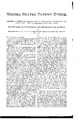
2 Sheets-Shee 1.
I G. M. PETERS.
FIFTH-WHEEL AND HEAD-BLOCK FOR VEHICLES. 10,135,349, Patented Dec. 12, 1876.
2Sheets-Sheet 2. G. M. PETERS. FIFTH-WHEEL AND HEAD-BLOCK FOR VEHICLES. No.185,349. Patented. Dec.12, 1876.
THE GRAPHIC C0. NvY
GEORGE M. PETERS, OF COLUMBUS, OHIO, ASSIGNOR OF ONE-HALF OF HIS RIGHT TO CLINTON D. FIRESTONE, OF SAME PLACE.
IMPROVEMENT I N FIFTH-WHEELS AND HEAD-BLOCKS FOR VEHlCLES.
Specification forming part of Letters Patent No. 185,349, dated December 12, 1876; application filed May 6, 1875.
To all whom t'tmay concern:
Be it known that I, GEORGE M. PETERS, a resident of the city of Columbus and State of Ohio, have invented certain new and useful Improvements in the Forward Running- Gear of Vehicles, of which the following is a specification My improvements, in general, relate to the construction of the head-block, fifth-wheel,
of this specification, Figure 1, Sheet 1, is a view in perspective of those portions of the running-gear of a road-vehicle which embody my improvements. Fig. 2, Sheet 1, represents a central longitudinal section of the lower half of the fifth-wheel, made after my improved plan, and secured to the axle by a clip. Fig. 3, Sheet 1, represents a cross vertical section through the center of the device shown in Fig. 2, but modified as to the means whereby it is secured to the axle, a bolt being employed instead of a clip. Fig. 4, Sheet 2, represents the guard attached to the lateral flanges near the ends of the head-block, and to the cars which receive the spring-clips, these ears being cast to the head-block, a portion of the latter being here shown. Fig. 5,
Sheet 2, represents the guard attached to the fifth-wheel or lateral flanges of the head-block, and to the front extension of the latter. Fig. 6, Sheet 2, represents a vertical longitudinal section through the center of the head-block rest, the front axle, the king-bolt, and those parts of the head-block adjacent thereto.
A designates the head-block, having an opening, B, in the middle, and provided near each end with lateral flanges O C. These flanges extend on opposite sides of the headblock, and are so located as to come over the upper-side of the fifth-wheel at the point where the latter touches the head-block. These flanges are, preferably, strengthened by bridging ridges or braces a, which curve upward into a pointed ridge, and which increase in size as they approach the headblock. At the intersection of the head-block and fifth-wheel they are connected together by a rivet or bolt, b, the bolt being passed through holes, preferably cast in the headblock and fifth-wheel. These flanges also stiffen or support the upper fifth-wheel where it is weakest, where the hole is through it. At the intersection of the fifth-wheel and head-block the latter is usually subjected to a severe torsion-strain, and the flanges O and O protect the head-block from any injury which otherwise might arise from this strain. Across the middle of the bottom of the opening B extends the bridge D, attached to each side of the head-block, being, preferably, cast in the same piece as the latter. The lower outer edge of this bridge terminates in a flange, b, which embraces the journal-seat or vertical portion F within head-block bedplate E, or axle bed-plate, as it might be termed. Both bridge 1) and journal F, and the axle H and the forward end of the perch, are pierced, and the kin g-bolt I passes through them. The head of the king-bolt is countersunk in the end of the perch, and rests upon the latter, the bolt itself being tightened by the nut 1' below the axle and screw-thread upon the lower end of the bolt. The object and advantage of the flange b is to give greater bearing-surface between the'headblock and bed-plate E; and also, by encircling the seat of the latter, to prevent the axle, and also the .lower part of the fifth-wheel, from sliding out of place in case the kingbolt should be worn through or broken by accident.
I will now describe the construction of the bed-plate E. This. plate has been already mentioned; is provided with a journal or seat, F. It is likewise provided with two flanges, J, one of which extends from either side of the journal-seat F in such a direction as to be directly over the axle and rest upon the latter. The bed-plate is further provided with two flanges, K, extending from opposite sides of the bottom of the journal-seat, and across the top of the axle, one of the flanges passingflange over the rear of the same. The axle bed-plate is usually secured to the axle by means of a screw, m, through each flange K, screwing into the axle H.
The function of the flanges J, and more especially that of the flanges K, is to prevent the axle-bed being moved out of place, as the strain on it will be greater than upon any ordinary axle bed-plate, as the bed E assumes a great portion of the strain and wear naturally belonging to the king-bolt. The flanges K are necessary.
At the front of the head-block, is an extension, L, which may be termed the front extension of the perch or T-plate, provided with a hole, I, for the attachment of the axle-strap. This extension L is preferably cast in one and the same piece with the head-block. In front of the head-block is a guard, G, cast solid onto the ends of the front lateral flanges O of the head-block, or the ends ofthe fifth-wheel, if preferred. This guard is also cast to the ears M, for the spring-clips, and also to the front extension L. In some instances the guard may preferably be attached to the front extension L, and not to the ears M, as shown in Fig. 6, Sheet 2. It may be found desirable, also, to cast the guard fast to the ears M, and not to the front extension, as shown in Fig. 5, Sheet2. Thepurpose of the guard is to strengthen and brace the head-block and the front ex tension and the ears, according as it is attached to one or the other of the same. An extension, N, for the perch or reach, is cast to the rear lower side of the head-block. This extension is sufficiently large to rest upon the upper fifth-wheel, and is adapted to rest thereon by means of the hollow pillow Q cast to the under side of the extension N, and fitting over the rounded top of the fifth-wheel. The perch or reach 0 rests on the top of the reach, and is secured to the same by the bolts r.
To stifl'en the sides of extension N, and more fully secure the perch in position upon the extension N, the flanges 8 may be cast with the extension, which flanges embrace the sides of the perch. The perch may, if desired, be stiffened by strips of iron placed along its sides and bottom, the strips being held in position by suitable holes through the perch. The clipframe has lips or flanges V on its side, which extend along upon the axle and parallel to the length of the latter. The clipframe is likewise provided with flanges X, which extend down on either or both sides of the axle. (See Fig. 2.) This clip-frame has a hole through the center, through which passes a bolt, Y, whose head is counter-sunk in the top of the lower fifthwheel U, and whose shank passes through the axle and is secured in position. Instead of a central hole for a single bolt, whenever greater strength is needed the clip-frame is pierced by two holes, one of which extends down through or along side either flange X.
The top of the fifth-wheel in a straight line between the two holes is countersunk for the reception of the bridges ofa clip, Z, one whose legs, Z, extend through or down on the outside, as preferred, of each of the flanges, and
terminate below the latter in screw threadedends, which pass through a plate, t, and receive nuts 15, by which the plate and clipframe are caused to tightly embrace the axle.
It may be here remarked that the ends of the guard G may be attached to the sides of the head-block, and yet substantially perform the functions of a guard. I believe I am the first to employ a guard for the mutual support of the front extension or the ears, or both, and hence claim all the advantages arising from such novel and useful employment.
Having thus described my invention, what I claim as new, and desire to secure by Letters Patent, is
l. A head-block, provided with flanges G U, for combination with a fifth-Wheel, substantially as set forth.
2. The guard G, in combination with a headblock and front extension, L, the said guard being attached to both the head-block and the front extension.
3. The guard G, in combination with a headblock and ears M, the said guard being attached to the head-block and the ears.
4. The guard G, in combination with a headblock, front extension L, and ears M, said guard being attached to the said head-block, front extension, and ears.
5. An upper fifth-Wheel, in combination with a head-block, flanges O, perch-plate N, and perch-rest Q, the head block flanges, perchplate, and rest being formed in one piece, and adapted to being laid upon the said upper fifth-wheel.
6. In combination, the king-bolt I, and a head-block provided with the flanged bridge D b, and the axle-bed .E, provided with journal or seat F, and lateral flanges K, with or without flanges J, substantially as and for the purposes set forth.
GEORGE M. PETERS.
Attest:
A. H. FRITOHEY, D. O. WELLING.
Publications (1)
| Publication Number | Publication Date |
|---|---|
| US185349A true US185349A (en) | 1876-12-12 |
Family
ID=2254755
Family Applications (1)
| Application Number | Title | Priority Date | Filing Date |
|---|---|---|---|
| US185349D Expired - Lifetime US185349A (en) | Improvement in fifth-wheels and head-blocks for vehicles |
Country Status (1)
| Country | Link |
|---|---|
| US (1) | US185349A (en) |
-
0
- US US185349D patent/US185349A/en not_active Expired - Lifetime
Similar Documents
| Publication | Publication Date | Title |
|---|---|---|
| US185349A (en) | Improvement in fifth-wheels and head-blocks for vehicles | |
| US311654A (en) | Running-gear for vehicles | |
| US972658A (en) | Running-gear for vehicles. | |
| US578576A (en) | morrill | |
| US430291A (en) | Bolster-plate | |
| US139588A (en) | Improvement in running-gears of wagons | |
| US446656A (en) | bartholomew | |
| US590251A (en) | Timothy l | |
| US140676A (en) | Improvement in fifth-wheels for vehicles | |
| US464050A (en) | Carriage-gear | |
| US332084A (en) | Milton keech and joseph labebdee | |
| US229237A (en) | Running-gear for vehicles | |
| US755231A (en) | Fifth-wheel construction. | |
| US255288A (en) | Head-block for side-bar buggies | |
| US269284A (en) | Wagon | |
| US184574A (en) | Improvement in draft attachments | |
| US816168A (en) | Fifth-wheel for vehicles. | |
| US415096A (en) | Spring-platform for vehicles | |
| US465370A (en) | Wagon running-gear | |
| US166323A (en) | Improvement in king-bolts for wagons | |
| US306853A (en) | Wagon running-gear | |
| US602655A (en) | Vehicle running-gear | |
| US375765A (en) | Vehicle gear-iron | |
| US223001A (en) | Improvement in fifth-wheels for vehicles | |
| US602511A (en) | Vehicle running-gear |