US1853410A - Towing and hauling car - Google Patents
Towing and hauling car Download PDFInfo
- Publication number
- US1853410A US1853410A US450036A US45003630A US1853410A US 1853410 A US1853410 A US 1853410A US 450036 A US450036 A US 450036A US 45003630 A US45003630 A US 45003630A US 1853410 A US1853410 A US 1853410A
- Authority
- US
- United States
- Prior art keywords
- towing
- bar
- truck
- secured
- shaft
- Prior art date
- Legal status (The legal status is an assumption and is not a legal conclusion. Google has not performed a legal analysis and makes no representation as to the accuracy of the status listed.)
- Expired - Lifetime
Links
Images

Classifications
-
- B—PERFORMING OPERATIONS; TRANSPORTING
- B60—VEHICLES IN GENERAL
- B60P—VEHICLES ADAPTED FOR LOAD TRANSPORTATION OR TO TRANSPORT, TO CARRY, OR TO COMPRISE SPECIAL LOADS OR OBJECTS
- B60P3/00—Vehicles adapted to transport, to carry or to comprise special loads or objects
- B60P3/12—Vehicles adapted to transport, to carry or to comprise special loads or objects for salvaging damaged vehicles
- B60P3/125—Vehicles adapted to transport, to carry or to comprise special loads or objects for salvaging damaged vehicles by supporting only part of the vehicle, e.g. front- or rear-axle
Definitions
- This invention relates to a truck designed primarily for use in lifting and towing automobiles, the primary object of the invention being to provide a 4truck of this character l supplied with gearing for winding allfting cable, the gearing being so constructed that an exceptionally heavy load may be lifted with a minimum amount of exertion on the part of the operator.
- Another object of the invention is to provide gearing having means whereby the cable and weight supported thereby, will be held in an elevated position while the towing bar, forming a part of the invention, is positioned on the wrecked automobile.
- a still further object of the invention is to provide a towing bar which may be readily and easily secured to the front aXle of the wrecked automobile, the towing bar being such that the wrecked automobile will be guided, as it is being towed.
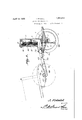
- Figure 1 is a rear elevational view of a truck constructed in accordance with the invention, a portion of the gear housing being gearing housed removed to illustrate the thereby.
- Figure 2 is an elevational view illustrating the rear end of a wrecking truck, showing the same as connected with a wrecked automobile, the gear housing being shown in section.
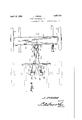
- Figure 3 is a transverse sectional view through the gear housing.
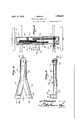
- Figure 4 is a longitudinal sectional viewv through the towing bar.
- Figure 5 is a sectional View taken on line 5-5 of Figure 4c.
- Figure 6 is a plan view illustrating the 1930. seria1 N6. 450,036.
- the reference vcharacter 5y designatesthe rear end ,o of a towing truck, constructed inf 'accordance 56 with the inven'tiointhe reference'character 6 designating the wheels mounted at the ends of the axle Y I
- the towing truck includes bars 7 that are@ secured to the rear axle 5l by means'of the' 60 springs A8', the vfront ends ⁇ of the bars ⁇ resting on the front axle of the truck, not shown.
- Mounted at the rear of the truck is a gearing housing 9 that includes spaced walls, the walls having openings providing bearings for the various shafts of the gearing.
- the reference character lO designates a shaft on which the pinion 11 is mounted, the pinion being secured to the shaft 10 to rotateY there.w with.
- One .end of the shaft 10 extends ⁇ 10 through the housing to receive a suitable crank handle 12, whereby rotary movement may be imparted to the shaft 10 to rotate the pinion 11.
- a substantiallylarge gear 13 is mounted "75 on the shaft 14 Vand is in mesh with'the pinion 11 to receive rotary motion therefrom, the gearing being secured to yshaft 14 tol rotate the shaft therewith.
- ⁇ A ⁇ substantially small.
- gear 15 is also secured to the shaft 14 and is"'80 in mesh withl the f gear 16 to which the pulley 17 is secured, the pulley 17 being designed .to receive the lifting cable 18, which a'sshown is wound thereon.
- a ratchet-B5 wheel 19 Secured tothe shaft'lS i., on which the gear 16 is mounted, is a ratchet-B5 wheel 19 that is engaged by the pawl20, so that reverse movement of the gear land pulley 17 is prevented, to the' end that' the cable 18may be moved to a position t0 lele-T vate the load lifted thereby, whereupon 'thew cable will be held against unwinding, to the end that the load will be vheldin its elevatedposition.
- a rod 21 that extends through an openingin the housing 9, the outer end of the-rod 21 being formed into a handle to permit the rodto be foperated by the attendant;
- the inner endlof this rod 21 is secured to the pawl 2O so that by lifting the rod 21, the' pawl y20 may be'floo "ao i 10 hicle or rod to be lifted. It will of course be obvious that when the'hook 23 has been properly positioned, the operator by rotating the shaft 10 may wind the cable-'on the pulley 17 withthe minimum amount ofexertion.
- rlhe towing bar is indicated generally by the reference character Y23. and includes a ltubular body portion 24 formed with lateral extensions 25 and 26. Upstanding hooks 27 are'formed ⁇ at Ithe endsof the extensions 25 and;26, theupper ends ,of the hooksv27l extending inwardly as at 28, the hooks being so kingfingers adapted to move into engagement with the hook members to close the hook members over the axle to which they are securedya bar extending into the tubular body portion and adapted to engage one end of the slidable member to restrict movement of the slidable member and hold the slidable member into engagement with the car axle with which the towing bar is connected.
- the forward end of the slidable member y29 extends toa position in spacedv ⁇ relation l with the front end of the bodyportion where it ,may be engaged by the pivoted bar 31 that connection with theV towing truck, the bar 31 acting to move the member 29 to its lockingposition.
- apin such asindicated at 32 is inserted in theregistering openings of the member 24C and bar 3'1, securing the member, 31 to the-member 24 insuch a way that .the wrecked automobile maybe not only supported in its elevated position, but willbe guided to permit the towing Yofthe wrecked automobile, with facility.
- atransversely extended bar 33 adapted to rest4 on the frame of the vehicle being towed,fto insure arigid connection between thetowing bar and vehicle being-towed.
- a hook 33 is formedat theforward end of the member 24 and affords means vwhereby the connecting bar may-bev secured within the wrecking truck.V Y Y- v. It might ⁇ be further stated that the truck .may-be propelledin any well known .the construction and operation of the truck being immaterial. 1 Y.
- a towing/bar comprising a tubular body portion, hook members'formed at oneA end of the body portion and adapted to hook over the axle of a vehicle to betowed, a movable ⁇ member mounted-within the body-portion,
Landscapes
- Engineering & Computer Science (AREA)
- Health & Medical Sciences (AREA)
- Public Health (AREA)
- Transportation (AREA)
- Mechanical Engineering (AREA)
- Vehicle Cleaning, Maintenance, Repair, Refitting, And Outriggers (AREA)
Description
April 12, 1932. 1 FRlEDEL 1,853,410
TOWING AND HAULING CAR Filed May 5, 1930 4 sheeS-sheet 2 tlopmm o'.
Filed May 5, 1950 4 Sheets-Sheet 5 April 12, 1932. J. FRIEDEL.
TovI-NG AND HAULING CAR Filed May 5, 1930 4 Sheets-SheekI 4 Patented Apr. 12, 1932 UNITED STAT-Es JONAS FRIIELDIELII,l 0F
OMAHA, NEBRASKA 4 TO-WINGAND HAULING CAR Application led May 5,
This invention relates to a truck designed primarily for use in lifting and towing automobiles, the primary object of the invention being to provide a 4truck of this character l supplied with gearing for winding allfting cable, the gearing being so constructed that an exceptionally heavy load may be lifted with a minimum amount of exertion on the part of the operator.
Another object of the invention is to provide gearing having means whereby the cable and weight supported thereby, will be held in an elevated position while the towing bar, forming a part of the invention, is positioned on the wrecked automobile.
A still further object of the invention is to provide a towing bar which may be readily and easily secured to the front aXle of the wrecked automobile, the towing bar being such that the wrecked automobile will be guided, as it is being towed.
With the foregoing and other objects in view, which will appear as the description proceeds, the invention resides in the combination and arrangement of parts and in the details of construction hereinafter described and claimed, it being understood that changes in the precise embodiment of the invention herein disclosed, may be made within the scope of what is claimed, without departing from the spirit of the invention.
Referring to the drawings:
Figure 1 is a rear elevational view of a truck constructed in accordance with the invention, a portion of the gear housing being gearing housed removed to illustrate the thereby.
Figure 2 is an elevational view illustrating the rear end of a wrecking truck, showing the same as connected with a wrecked automobile, the gear housing being shown in section.
Figure 3 is a transverse sectional view through the gear housing.
Figure 4 is a longitudinal sectional viewv through the towing bar.
Figure 5 is a sectional View taken on line 5-5 of Figure 4c.
Figure 6 is a plan view illustrating the 1930. seria1 N6. 450,036.
manner of connecting a wrecked automobile to the towing truck. ,i 7
` Referring tothe drawings in-detail,"the reference vcharacter 5y designatesthe rear end ,o of a towing truck, constructed inf 'accordance 56 with the inven'tiointhe reference'character 6 designating the wheels mounted at the ends of the axle Y I ,The towing truck includes bars 7 that are@ secured to the rear axle 5l by means'of the' 60 springs A8', the vfront ends `of the bars `resting on the front axle of the truck, not shown. Mounted at the rear of the truck, is a gearing housing 9 that includes spaced walls, the walls having openings providing bearings for the various shafts of the gearing. The reference character lOdesignates a shaft on which the pinion 11 is mounted, the pinion being secured to the shaft 10 to rotateY there.w with. One .end of the shaft 10 extends`10 through the housing to receive a suitable crank handle 12, whereby rotary movement may be imparted to the shaft 10 to rotate the pinion 11. v A
l A substantiallylarge gear 13 is mounted "75 on the shaft 14 Vand is in mesh with'the pinion 11 to receive rotary motion therefrom, the gearing being secured to yshaft 14 tol rotate the shaft therewith. `A` substantially small.,
Cooperating with the pawl 20 is a rod 21 that extends through an openingin the housing 9, the outer end of the-rod 21 being formed into a handle to permit the rodto be foperated by the attendant; The inner endlof this rod 21 is secured to the pawl 2O so that by lifting the rod 21, the' pawl y20 may be'floo "ao i 10 hicle or rod to be lifted. It will of course be obvious that when the'hook 23 has been properly positioned, the operator by rotating the shaft 10 may wind the cable-'on the pulley 17 withthe minimum amount ofexertion.
. rlhe towing bar is indicated generally by the reference character Y23. and includes a ltubular body portion 24 formed with lateral extensions 25 and 26. Upstanding hooks 27 are'formed` at Ithe endsof the extensions 25 and;26, theupper ends ,of the hooksv27l extending inwardly as at 28, the hooks being so kingfingers adapted to move into engagement with the hook members to close the hook members over the axle to which they are securedya bar extending into the tubular body portion and adapted to engage one end of the slidable member to restrict movement of the slidable member and hold the slidable member into engagement with the car axle with which the towing bar is connected.
Intestimony that I claim the foregoing as i my own, I have hereto affixed my signature.
JONAS FRIEDEL.
constructed that they will overlie theV .upper Y' edge of the front axle of a motor vehicle. Cooperating with the inwardly extended Yends 28,:of the hooks 27, isI a slidablepmember 29, thath-as` upstanding fingers adapted to move tov engage the innerl edges of the inwardly extended portions 28, to lock the hooks on the axle.-
The forward end of the slidable member y29 extends toa position in spacedv` relation l with the front end of the bodyportion where it ,may be engaged by the pivoted bar 31 that connection with theV towing truck, the bar 31 acting to move the member 29 to its lockingposition. vWhen the member y29 has been V -moved to its active or lockingposition, apin such asindicated at 32 is inserted in theregistering openings of the member 24C and bar 3'1, securing the member, 31 to the-member 24 insuch a way that .the wrecked automobile maybe not only supported in its elevated position, but willbe guided to permit the towing Yofthe wrecked automobile, with facility.
Secured to the upper surface of the member 24k-.is atransversely extended bar 33 adapted to rest4 on the frame of the vehicle being towed,fto insure arigid connection between thetowing bar and vehicle being-towed. A hook 33 is formedat theforward end of the member 24 and affords means vwhereby the connecting bar may-bev secured within the wrecking truck.V Y Y- v. It might `be further stated that the truck .may-be propelledin any well known .the construction and operation of the truck being immaterial. 1 Y.
Iclaim;v 1. A towing/bar comprisinga tubular body portion, hook members'formed at oneA end of the body portion and adapted to hook over the axle of a vehicle to betowed, a movable `member mounted-within the body-portion,
upstanding fingers at one end of the movable Ifil()
Priority Applications (1)
| Application Number | Priority Date | Filing Date | Title |
|---|---|---|---|
| US450036A US1853410A (en) | 1930-05-05 | 1930-05-05 | Towing and hauling car |
Applications Claiming Priority (1)
| Application Number | Priority Date | Filing Date | Title |
|---|---|---|---|
| US450036A US1853410A (en) | 1930-05-05 | 1930-05-05 | Towing and hauling car |
Publications (1)
| Publication Number | Publication Date |
|---|---|
| US1853410A true US1853410A (en) | 1932-04-12 |
Family
ID=23786501
Family Applications (1)
| Application Number | Title | Priority Date | Filing Date |
|---|---|---|---|
| US450036A Expired - Lifetime US1853410A (en) | 1930-05-05 | 1930-05-05 | Towing and hauling car |
Country Status (1)
| Country | Link |
|---|---|
| US (1) | US1853410A (en) |
Cited By (1)
| Publication number | Priority date | Publication date | Assignee | Title |
|---|---|---|---|---|
| US3021166A (en) * | 1959-12-08 | 1962-02-13 | Kempel Hubert | Vehicle hoisting arrangement |
-
1930
- 1930-05-05 US US450036A patent/US1853410A/en not_active Expired - Lifetime
Cited By (1)
| Publication number | Priority date | Publication date | Assignee | Title |
|---|---|---|---|---|
| US3021166A (en) * | 1959-12-08 | 1962-02-13 | Kempel Hubert | Vehicle hoisting arrangement |
Similar Documents
| Publication | Publication Date | Title |
|---|---|---|
| US2740639A (en) | Vertically adjustable trailer suspension | |
| US1853410A (en) | Towing and hauling car | |
| US1806606A (en) | Auto towing device | |
| US7547025B2 (en) | Assembly and method for lowering and raising a transport trailer bed for loading and unloading a trailer | |
| US2465244A (en) | Trailer lift | |
| DE375840C (en) | Motor vehicle coupling for trailer vehicles with swiveling coupling tension member | |
| US1569498A (en) | Trailer truck | |
| US1537213A (en) | Extension hitch | |
| DE429615C (en) | Device for coupling the towing vehicle and trailer to a winch drum mounted on the towing vehicle and driven by the vehicle engine for a rope attached to the trailer | |
| DE348249C (en) | On the vehicle, in particular a motor vehicle, arranged with a winch loading device for piece goods | |
| US1854055A (en) | Pulling jack | |
| US2054800A (en) | Load supporting device for automobiles | |
| US2615538A (en) | Collapsible derrick | |
| DE451704C (en) | Device for loading and unloading motor vehicles | |
| US2307611A (en) | Wrecking truck | |
| US1313087A (en) | hartwick | |
| US1423638A (en) | Mechanical hoist | |
| US1649084A (en) | Folding towing device for automobiles | |
| US2008553A (en) | Vehicle jack | |
| US1512429A (en) | Service hoist | |
| US1783224A (en) | Lifting device for motor vehicles | |
| CH133655A (en) | Lifting device for the wheels of motor vehicles. | |
| AT145903B (en) | Towing and truck with three or more driving axles. | |
| US2036006A (en) | Elevator for wheeled vehicles | |
| US1738924A (en) | Power take-off |