US1854055A - Pulling jack - Google Patents
Pulling jack Download PDFInfo
- Publication number
- US1854055A US1854055A US517286A US51728631A US1854055A US 1854055 A US1854055 A US 1854055A US 517286 A US517286 A US 517286A US 51728631 A US51728631 A US 51728631A US 1854055 A US1854055 A US 1854055A
- Authority
- US
- United States
- Prior art keywords
- chain
- tubular member
- rod
- sleeve
- base
- Prior art date
- Legal status (The legal status is an assumption and is not a legal conclusion. Google has not performed a legal analysis and makes no representation as to the accuracy of the status listed.)
- Expired - Lifetime
Links
- 238000010276 construction Methods 0.000 description 3
- 210000000078 claw Anatomy 0.000 description 2
- 208000003251 Pruritus Diseases 0.000 description 1
- 239000003129 oil well Substances 0.000 description 1
- 229920000136 polysorbate Polymers 0.000 description 1
Images
Classifications
-
- B—PERFORMING OPERATIONS; TRANSPORTING
- B66—HOISTING; LIFTING; HAULING
- B66F—HOISTING, LIFTING, HAULING OR PUSHING, NOT OTHERWISE PROVIDED FOR, e.g. DEVICES WHICH APPLY A LIFTING OR PUSHING FORCE DIRECTLY TO THE SURFACE OF A LOAD
- B66F3/00—Devices, e.g. jacks, adapted for uninterrupted lifting of loads
- B66F3/08—Devices, e.g. jacks, adapted for uninterrupted lifting of loads screw operated
- B66F3/14—Devices, e.g. jacks, adapted for uninterrupted lifting of loads screw operated actuated through pawl-and-ratchet mechanisms
-
- B—PERFORMING OPERATIONS; TRANSPORTING
- B66—HOISTING; LIFTING; HAULING
- B66F—HOISTING, LIFTING, HAULING OR PUSHING, NOT OTHERWISE PROVIDED FOR, e.g. DEVICES WHICH APPLY A LIFTING OR PUSHING FORCE DIRECTLY TO THE SURFACE OF A LOAD
- B66F3/00—Devices, e.g. jacks, adapted for uninterrupted lifting of loads
- B66F3/08—Devices, e.g. jacks, adapted for uninterrupted lifting of loads screw operated
- B66F3/16—Devices, e.g. jacks, adapted for uninterrupted lifting of loads screw operated actuated through bevel-wheel gearings
Definitions
- This invention relates to improvements in 8 formed integral with one end of a tubular pulling jacks adaptable for many purposes, member 4.
- a combined handle and arm 5 such as, to move heavy loads, to tighten is formed integral with the base 1 and tuchains and the like around objects that may bular member 4; and is of a greater height be the load on a truck, or the tying together than the arms 3 for supporting the tubular '65 of oil well equipment, lumber and the like member in an inclined position as shown in or the moving of stalled vehicles, and has Figure 2.
- tubular member 1 for the primary object, the provision of a A'feed rod 6 is slidably mounted in the device of the above stated character which tubular member 1 and is provided with feed 19 will act with a great amount of force or threads 7 meshing with corresponding feed .60 strength with the expenditure of a minimum threads in a sleeve 8 at the upper end of the amount of effort on the part of the operator. tubular member 4.
- a hand wheel 9 is Another object of this invention is the formed integral with thesleeve 8 whereby provision of means, whereby the device may the latter may be quickly rotatedin either be easily and quickly adjusted to remove surdirection for the purpose of adjusting the 65 plus slack in a tying or towing chain, placrod 6 within the tubular member 4; A poring the latter with sufl'icient tautness so that tion of the sleeve 8 is formed to provide a when the actuating member is manually gear 10 Ineshing with a gear 11 journalled 0 moved, the chain may be made as taut as deon a shaft 12 carried by the upper end of M sired without undue effort on the part of the tubular member-4c. An operating lever the operator.
- a further object of this invention is the shown in Figure 2 and is provided with a provision of a device of the above stated double dogcl lfor the purpose of rotating N character which is of a construction capable the gear 11 in opposite directions by the 0s of aflording maximum strength with comcillation of the lever 13.
- the directionof pactness that will provide the greatest ease rotation of the gear 11 depends upon which in handling from one place to another, which end of the dog 14' is engaged therewith.
- Figure 2 1 s a sectional view taken on the the'feed rod 6 and thesleeve 8 it is possible if line 22 of Figure 1. to adjust the tautness of the chain down to Referring n det il to the d g t a fraction of an inch and after the chain numeral 1 indicates an elongated base'prohas been properly adjusted, the'feedrod and vided with slde marginal flanges 2 that are sleeve 8 will maintain the chain in'its adr. extended at one of their ends to provide iuste d position. that the operator may fasten 10G arcuately curved supporting and guide arms the chain with the jack unattended.
- a retaining chain 20 is 1 provided and is attached to the base as shown at 21 and is provided with a claw hook 22 whereby the chain 20 may be hitched to the towing chain maintaining the latter taut while the hook 19 is detached and the feed rod 6 adjusted inwardly of the member 4 that a further hitching may be had upon the towing chain and the operation of the jack repeated.
- the base 1 has the forward end thereof slotted as shown at 23 to permit free movement of the chains 20' and 18 and the outer end of the rod 6 is provided with a pin 24 to prevent the sleeve 8 from threading entirely off the rod.
- One of the arms 3 carries a 25 notched bracket 25 adapted to form a rest for the lever 13 when in an inactive position.
- a pulling jack comprising a base, an inclined tubular member mounted on the base, a rod slidable in the tubular member, feed threads on said rod, a feed sleeve engaging said threads and one end of the tubular member, a hand wheel carried by said sleeve for providing quick adjustment of the rod relative to the tubular member, a gear formed integral with the sleeve, a second gear journalled on the tubular member and meshing with the first gear, a pivotally mounted lever associated with the second gear, a pivoted dog on the lever to engage the second gear, and an object engaging means connected to the rod.
- a pulling jack comprising an elongated base, flanges on said base, said flanges having portions thereof extended and curved to form attaching arms at one end of said base, a combined handle and arm formed on the other end of said base independent of said first arms, a tubular member formed on said arms, a feed rod slidable in the tubular member, means for actuating said feed ro'd, said tubular member having a slot, a sleeve secured to the rod, an ear formed on the sleeve and extending through the slot, and an attaching element connected to the ear and operable be tween the first named arms.
Landscapes
- Life Sciences & Earth Sciences (AREA)
- Engineering & Computer Science (AREA)
- Geology (AREA)
- Mechanical Engineering (AREA)
- Structural Engineering (AREA)
- Hand Tools For Fitting Together And Separating, Or Other Hand Tools (AREA)
Description
s. .1. MONTGOMERY. 1,854,055
PULLING JACK April 12, 1932.
y y Y JZMea/aZZJMiZ/WW ATTORNEY Patented Apr. 12, 1932 v g 1 PATENT itch sronnwnrm a. MONTGOMERY OF cnnan VALE, Kansas PULLING moi:
Application filed February 20; 1931. Serial No. 517,286.
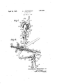
This invention relates to improvements in 8 formed integral with one end of a tubular pulling jacks adaptable for many purposes, member 4. A combined handle and arm 5 such as, to move heavy loads, to tighten is formed integral with the base 1 and tuchains and the like around objects that may bular member 4; and is of a greater height be the load on a truck, or the tying together than the arms 3 for supporting the tubular '65 of oil well equipment, lumber and the like member in an inclined position as shown in or the moving of stalled vehicles, and has Figure 2. for the primary object, the provision of a A'feed rod 6 is slidably mounted in the device of the above stated character which tubular member 1 and is provided with feed 19 will act with a great amount of force or threads 7 meshing with corresponding feed .60 strength with the expenditure of a minimum threads in a sleeve 8 at the upper end of the amount of effort on the part of the operator. tubular member 4. A hand wheel 9 is Another object of this invention is the formed integral with thesleeve 8 whereby provision of means, whereby the device may the latter may be quickly rotatedin either be easily and quickly adjusted to remove surdirection for the purpose of adjusting the 65 plus slack in a tying or towing chain, placrod 6 within the tubular member 4; A poring the latter with sufl'icient tautness so that tion of the sleeve 8 is formed to provide a when the actuating member is manually gear 10 Ineshing with a gear 11 journalled 0 moved, the chain may be made as taut as deon a shaft 12 carried by the upper end of M sired without undue effort on the part of the tubular member-4c. An operating lever the operator. 13 is journalled on the shaft'lQ as'clearly A further object of this invention is the shown in Figure 2 and is provided with a provision of a device of the above stated double dogcl lfor the purpose of rotating N character which is of a construction capable the gear 11 in opposite directions by the 0s of aflording maximum strength with comcillation of the lever 13. The directionof pactness that will provide the greatest ease rotation of the gear 11 depends upon which in handling from one place to another, which end of the dog 14' is engaged therewith. will be Simple, durab e and efi c and A sleeve 15 is secured to the lower end of which may be manufactured and sold at a th d 6 d i id d ith an apertured comparatively low cost. ear 16 extending through a slot 17 formed in 7 With these and other objects in view, as the lower wall of the member and has a will become more apparent as the descripchain or flexible element 18 connected thereto tion proceeds, this invention consists in cera d whi h arriage, law hook 19 to ngage M tain novel features of construction, combinawith one of the links of a tying or towing tion and arrangement of parts to be herechain (not shown). The base'l is anchored in inafter more fully described and claimed. any desired manner preferably by securing For a complete understanding of my inan anchor chain about the combined handle vention, reference is to be had to the followand arm 5. and with the claw hook 19 at- I, r, ing description and accompanying drawings tached tothe tying ortowing chain and oscilin whlch lating the handle 13, the slack of the tying or 90 Figure 1 is an end elevation illustrating a towingchain may be easily removed therejack constructed in accordance with my infrom with a minimum expenditure of efl'ort vention. V on the part of the operator." By employing I, Figure 2 1s a sectional view taken on the the'feed rod 6 and thesleeve 8 it is possible if line 22 of Figure 1. to adjust the tautness of the chain down to Referring n det il to the d g t a fraction of an inch and after the chain numeral 1 indicates an elongated base'prohas been properly adjusted, the'feedrod and vided with slde marginal flanges 2 that are sleeve 8 will maintain the chain in'its adr. extended at one of their ends to provide iuste d position. that the operator may fasten 10G arcuately curved supporting and guide arms the chain with the jack unattended.
When desiring to employ the device for moving a stalled vehicle or for moving a heavy load from one place to another, the hook 19 is engaged with the towing chain and 5 the lever operated in the manner heretofore described, and after the load or vehicle has been moved a distance equal to the movement of the rod 6 and it is desired to move the load or vehicle further, a retaining chain 20 is 1 provided and is attached to the base as shown at 21 and is provided with a claw hook 22 whereby the chain 20 may be hitched to the towing chain maintaining the latter taut while the hook 19 is detached and the feed rod 6 adjusted inwardly of the member 4 that a further hitching may be had upon the towing chain and the operation of the jack repeated.
The base 1 has the forward end thereof slotted as shown at 23 to permit free movement of the chains 20' and 18 and the outer end of the rod 6 is provided with a pin 24 to prevent the sleeve 8 from threading entirely off the rod. One of the arms 3 carries a 25 notched bracket 25 adapted to form a rest for the lever 13 when in an inactive position.
While I have shown and described the pre ferred embodiment of my invention, it will be understood that minor changes in construction, combination. and arrangement of parts may be made without departing from the spirit and scope of the invention as claimed.
Having thus described my invention, what I claim is:
1. A pulling jack comprising a base, an inclined tubular member mounted on the base, a rod slidable in the tubular member, feed threads on said rod, a feed sleeve engaging said threads and one end of the tubular member, a hand wheel carried by said sleeve for providing quick adjustment of the rod relative to the tubular member, a gear formed integral with the sleeve, a second gear journalled on the tubular member and meshing with the first gear, a pivotally mounted lever associated with the second gear, a pivoted dog on the lever to engage the second gear, and an object engaging means connected to the rod.
2. A pulling jack comprising an elongated base, flanges on said base, said flanges having portions thereof extended and curved to form attaching arms at one end of said base, a combined handle and arm formed on the other end of said base independent of said first arms, a tubular member formed on said arms, a feed rod slidable in the tubular member, means for actuating said feed ro'd, said tubular member having a slot, a sleeve secured to the rod, an ear formed on the sleeve and extending through the slot, and an attaching element connected to the ear and operable be tween the first named arms.
In testimony whereof I affix my signature. STONEWALL J. MONTGOMERY.
Priority Applications (1)
| Application Number | Priority Date | Filing Date | Title |
|---|---|---|---|
| US517286A US1854055A (en) | 1931-02-20 | 1931-02-20 | Pulling jack |
Applications Claiming Priority (1)
| Application Number | Priority Date | Filing Date | Title |
|---|---|---|---|
| US517286A US1854055A (en) | 1931-02-20 | 1931-02-20 | Pulling jack |
Publications (1)
| Publication Number | Publication Date |
|---|---|
| US1854055A true US1854055A (en) | 1932-04-12 |
Family
ID=24059174
Family Applications (1)
| Application Number | Title | Priority Date | Filing Date |
|---|---|---|---|
| US517286A Expired - Lifetime US1854055A (en) | 1931-02-20 | 1931-02-20 | Pulling jack |
Country Status (1)
| Country | Link |
|---|---|
| US (1) | US1854055A (en) |
Cited By (4)
| Publication number | Priority date | Publication date | Assignee | Title |
|---|---|---|---|---|
| US2455736A (en) * | 1946-05-07 | 1948-12-07 | Conley Clarence | Will cylinder velwe piller |
| US4100875A (en) * | 1977-03-28 | 1978-07-18 | Patterson Iii William W | Connectors |
| US4567627A (en) * | 1983-08-16 | 1986-02-04 | W. W. Patterson Company | Load binder apparatus |
| US4700559A (en) * | 1985-09-23 | 1987-10-20 | Larson Byron A | Apparatus for repairing deformed, yieldable structures |
-
1931
- 1931-02-20 US US517286A patent/US1854055A/en not_active Expired - Lifetime
Cited By (4)
| Publication number | Priority date | Publication date | Assignee | Title |
|---|---|---|---|---|
| US2455736A (en) * | 1946-05-07 | 1948-12-07 | Conley Clarence | Will cylinder velwe piller |
| US4100875A (en) * | 1977-03-28 | 1978-07-18 | Patterson Iii William W | Connectors |
| US4567627A (en) * | 1983-08-16 | 1986-02-04 | W. W. Patterson Company | Load binder apparatus |
| US4700559A (en) * | 1985-09-23 | 1987-10-20 | Larson Byron A | Apparatus for repairing deformed, yieldable structures |
Similar Documents
| Publication | Publication Date | Title |
|---|---|---|
| US11691559B2 (en) | Method of raising or lowering a landing gear | |
| US2628397A (en) | Hold down clamp | |
| US7407151B2 (en) | Integrated jack and winch assembly | |
| US2661130A (en) | Spare tire and wheel carrier | |
| US1854055A (en) | Pulling jack | |
| US2074616A (en) | Automobile tire chain | |
| US5297913A (en) | Spare tire hoist and carrier | |
| US2895714A (en) | Cable winch | |
| US3721356A (en) | Vehicle towing device | |
| US2198844A (en) | Hook-up boom | |
| US3262591A (en) | Winch-type camper coach loader and unloader | |
| US2120637A (en) | Coupler for trailing ordnance and the like | |
| US2606001A (en) | Tool transporter | |
| US3149821A (en) | Chain binder | |
| US2817537A (en) | Trailer for boats or the like | |
| US2812837A (en) | Interlock for transmission control and hand brake for automobiles | |
| US2387504A (en) | Trailer | |
| US2326618A (en) | Tire chain assembly | |
| US2928557A (en) | Wreckers | |
| US2469199A (en) | Lifting apparatus | |
| US3021812A (en) | Releasable anchor | |
| US2560695A (en) | Apparatus for securing cargo in transit | |
| US3108784A (en) | Vehicle jack structure with adjustable effective length lift means | |
| US2088828A (en) | Log skidding and loading hoist | |
| US2433567A (en) | Emergency tire chain for trucks |