US1853372A - Boiler - Google Patents
Boiler Download PDFInfo
- Publication number
- US1853372A US1853372A US208573A US20857327A US1853372A US 1853372 A US1853372 A US 1853372A US 208573 A US208573 A US 208573A US 20857327 A US20857327 A US 20857327A US 1853372 A US1853372 A US 1853372A
- Authority
- US
- United States
- Prior art keywords
- water
- tubes
- boiler
- legs
- segregated
- Prior art date
- Legal status (The legal status is an assumption and is not a legal conclusion. Google has not performed a legal analysis and makes no representation as to the accuracy of the status listed.)
- Expired - Lifetime
Links
Images


Classifications
-
- F—MECHANICAL ENGINEERING; LIGHTING; HEATING; WEAPONS; BLASTING
- F22—STEAM GENERATION
- F22B—METHODS OF STEAM GENERATION; STEAM BOILERS
- F22B17/00—Water-tube boilers of horizontally-inclined type, i.e. the water-tube sets being inclined slightly with respect to the horizontal plane
- F22B17/02—Water-tube boilers of horizontally-inclined type, i.e. the water-tube sets being inclined slightly with respect to the horizontal plane built-up from water-tube sets in abutting connection with two header boxes in common for all sets, e.g. with flat header boxes
Definitions
- This invention relates to improvements-in' o. 208,573 Renewed January-5,4932@ ,AS'AMEDED APRIL 30,1928; ⁇ 37oY o. G 'vs'rz) partsv "in all fthe 5 figures of thel draw-ings; in which: ⁇ y l v Y, 'Figs '1 isia 'side elevation of fmyilnproved* the'A furnaoereinoved.
- ⁇ Water tube" boilershowing tlieniearr Wallf'of-1 ⁇ Fig; 2 is ⁇ an'enlargedend ⁇ elevation ofthe? boiler havingcireularheadsiiorining itsvvater kyboiler ⁇ showing one-half ofv 4 Sandie* 'in Psectin' legs, said legsjbeingConnectedby steamk drum beneath which are arranged'the Water tube's,' 'the druin being fianked 'on' both sides;
- Fig; '5 isa verticallsectiona'l'View similarv to Fig. l, of a modified form of boiler wherein on y'line taken between thiesheets' of the 'near n 4 isja side' 'elevation ofthe partsshown n .horizontal baille'plates inay be used and an prevent jthe'fgases coming into* Contact With fi thedruniiabove'the'level oftheWatfer.
- y -Figi' 6 shows diagranimatieally'dierentpy types of boilers, to'assist' ⁇ in the understandv now in general use?
- YFgil is a'detail perspective viewf'offon'e y ofthe partitionl plates adaptedto beinounted" 'y inv'tlie 'Water vleg .tov provide thesegregatd' portionif'thereofl With which "theL tubes are in Communioation:
- Fig. .lO is a front view",fone Yhalf "sect-ion" ⁇ showing the improved iboilerinountingg Reference now being had'to the drawingsl y 85" preheating bymuinerals and to inaker' Clear' the relative'4 alllllgf'lleHS' oi parts' of' the improved boiler 'I as compared toboilers now on the market;spel4 cial reference is made to Fig: '6'in'whrchtlie ⁇ -vievv inarked A represents the forni oiboili- ⁇ er of the usualoonstruetiorrand referred to as-'a Water tube lboiler; "The-view; marked@ B?
- his invention is intended to provide a water tube boiler that will require little or no more head room than the ordinary fireV tube boilers, will have the efficiency of the-'water enced in the use of the present water tube boilers, which are partly illustrated in Fig. 6, view A wherein is shown in dotted lines in a diagrammatical manner, the variations that exist in the forms of boilers legs now in general use. variations inthe lower rectangular portion of the water legs as put out by different manufacturers for a given horsepower, the angle or taper of the upper portion of the water legs and the relative position of the steam drum. v y
- cement foundation A8 are all of standard construction.
- the boiler which is of the water tube type consists of circular water'legs 9 and 10, said water legs being of a. corresponding construction and are interchangeable, facilitating assembling and laying out.
- the water legs are The dotted lines indicate the connected by a steam drum 11, arranged between the upper portions of the circular legs.
- Water tubes are arranged beneath the steam drum as shown at 12 and nests of preheating tubes flank the steamdrum on both sides as shownat13.
- baflle plates 14 and 15 respectively are provided.
- a flue leading to the stack as indicated at 16 is provided i for the passage of the gases from the combustion chamber beneath the lower baille plate 15 rearwardly -and then upwardly around the end of the same, forwardly ,between the baffle plates 14 and 15, around the forward end of baille plate 14 and back on itself in a rearwardly direction tothe flue 16, it being noted in the arrangement of baille plates shown th atv the gases turn over three times which may be increased by a re-arrangement of baille plates in eitherfcase insuring a perfect mixture of the gases, preventing stratification thereof and producing more complete combustion.
- the circular water legs 9 and 10 at the ends of the boiler are identical in construction and a description of only one will be given.
- the Water leg consists of a tube sheet 21 (see Figs. 2 and 3) and a hand hole sheet 22.
- the tube sheet is preferably provided with flanges 23 and 24, and also with openings 25 and 26 in which the ends of water tubes 12 and preheating tubes 13 respectively, are secured in the usual manner.
- An end of the steam drum V11 snugly fits flange 23 of the tube sheet and is secured thereto by rivets or other preferred means.
- Drain or blow-off pipe opening 27 is provided at the lower portion of the water leg, from which pipe 28 (see Fig. 1) vmay extend to any desired point, it being noted that said drain or blow-ofi' pipe is fully protected throughout its entire length, from the direct heat of the furnace.
- Hand hole sheet 22 is preferably shaped steel as .is the tube sheet and is kprovided with a'llange 29, adapted to.
- segregated chambers 32 Arranged in the water leg oneach side of its connection with the steam drum, are segregated chambers 32 formed by plates 33 adapta counter How of the-liquidl-in Vthe tubes and the gases. i
- baffle plates are" lar ranged in ll- ⁇ a vertical 'position-1insteadfofffm horizontal Y positionIsf-as shown 'intheifpre-f peraturefof theravaterin'itspassage throng-li ferred forma# Y
- f1 baiil'eplate's l45"+.-%l6' cause the products f of 'combustion Y'tolA folle an upand down direction through the Water tubes' and lthat there 'areA-plates- 46a arranged on opposite sides of the steam drum to prevent any contact between the products Ofcombustion7 and the steam drum above the water line.
- the preheating tubes is brought to such a su'if# ItL is furtheri noted' 'ithatfjthere is j anfunl'f restricted fconrmunieatron 7 between the steam d1'-u1nfand the waiterflegs, this as ⁇ :1n numerous otherf-'particularsflis different from Ithe @usualpraeti'cefwherein thecOmmuniCatiOn ibetween t thefSteimJdr-UIHYaI-rd tlrewater leg is'fthrough slits'arranged around a yportion ofH the 'Giri cumfer'eneef'foffthe steam 'drumiil
- the .coni saturation-@here shown provides for free ⁇ circul lation andkmorerapld generation.
- The* construction shown 1 provides for fb' and includes in a single unit within safi'duni:
- the generator,r which may be providedwith corrugations to compensate for the movement of-the VWater legs due to irregular expansion of the tubes. It will also be understood that the inflow of cold water into the preheating tubes varies to a considerable degree, While the lower steam generating tubes remain at practically a .uniform temperature, said corrugations provide forthe movement of the Water legs due to the irregular expansion of the tubes.
- a Water tube boiler having circular water legs, segregated chambers arranged in the water legs, a steam drumandwater tubes connecting the waterlegs withinjthe diameter of said water legs,rpreheating tubes connecting the segregated chambers and means for Vsupplying water to the segregated chambers of one Water leg and from the segregated chambers of the other leg to thelast named water leg of the boiler.
- a water tube boiler having circular waterlegs, pairs of segregated chambers arranged in saidlegs, a steam drum and Water tubes in communication with the water legs and preheating tubesconnecting said segregated chambers of the water legs all within the-diameter of said legs, means for supplying water to the segregated chambers of one water leg and means forconveying water from the Vsegregated chambers to the water legs.
- Water vvlegs a steam drum connecting the upper portion of the waterlegs, segregated portions in the water legs on opposite sides of Ythe drum connections, vwatertubes convnecting the lower portion of the water legs,
- corrugated preheating tubes arranged on either side ofthe steam drum connecting the segregated portions of the Waterlegs, means for supplying the preheatin tubes with water and means for .conveylng preheated water from the preheating tubes to a water leU.
- a ⁇ water tube boiler having circular water legs, a steam drum connecting. the upper portions of the water legs, segregated chambers arranged in the water legs'on opposite sides of the steam drum connections,
- preheating tubes arranged on each side of the drum' and connecting. the; segregated chambers on corresponding sides of the steam drum, water tubes arranged below said steam drum and .preheating tubes, connecting the water legs, means for supplying water to the segregated chambers of one leg and means for conveying waterfrom the segregated chambersof the other'leg, to the last named water n 7.'
- the combination Withafurnacehavinga fire chamber, a flue andmeans adaptedto form circuitous gas passes between the fire chamber and the flue, of a tilted water tube boiler having circular water legs, segregated chambers within the water legs, a steam drum and water.
Landscapes
- Engineering & Computer Science (AREA)
- Physics & Mathematics (AREA)
- Thermal Sciences (AREA)
- Mechanical Engineering (AREA)
- General Engineering & Computer Science (AREA)
- Control Of Steam Boilers And Waste-Gas Boilers (AREA)
Description
April l2, 1932. M. E. MILLER 1,853,372
` BOILER Original Filed July 26. 1927 (Shees-Sheef. l
jVS :Eu-L4 April 12, 1932. M. E. MILLER BOILER Original Filed July 26. 192'7- 6 Sheets-Sheet April 12, 1932. M. E. MILLER 1,853,372
BOILER Orjiginal Filed July 26. 1927 6 Sheets-Sheet I5 :Ella- 3 LNE- 4 April 12, 1932 IM. E. MILLER 1,853,372
www@
l lli :ETE- .5
n L'fLs-- v 4 d A j, 8
g j i y A I f 'WWW/WMM April 12, 1932.
M. EY MILLER -BOILER OrgnaLFiled July 26. 1927 6 Sheets-Sheet 5 April 12, 1932 M. MILLER 1,853,372
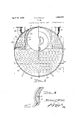
v BOILER Original Filed July 26. 1927 6 Sheets-Sheet 6 :EE- K10 l i l boilers' 'and'inoregpartieularlv to a Water tube-l' j Patented Apr. l2,` 1932 monnaie-nsimmmorfwnsmnerongamsrmor weones/remi# BorLER Appli'dation led'July -26ff1927ySerials-N (GRANTED minnen THE ser" er MARGH 2,. 1883' The invention deseribed'hereimif patented,`4Vv may 'be nianufactured'and 'used by-or-*for the Government. for governmental purposeswith?V out Vpayment'of anyroyalt-y thereon? This invention relates to improvements-in' o. 208,573 Renewed January-5,4932@ ,AS'AMEDED APRIL 30,1928;` 37oY o. G 'vs'rz) partsv "in all fthe 5 figures of thel draw-ings; in which:` y l v Y, 'Figs '1 isia 'side elevation of fmyilnproved* the'A furnaoereinoved.
`Water tube" boilershowing tlieniearr Wallf'of-1^` Fig; 2 is `an'enlargedend` elevation ofthe? boiler havingcireularheadsiiorining itsvvater kyboiler` showing one-half ofv 4 Sandie* 'in Psectin' legs, said legsjbeingConnectedby steamk drum beneath which are arranged'the Water tube's,' 'the druin being fianked 'on' both sides;
`vtubes? arranged beneath the steam levelf'4 With nests'of preheatingwater tubes *'c'onne'ctf n ing segregated" eompartinents formed-n: the
Water legs onl opposite sides 'of the ends ofthe l drinn, saidpre-heiating tubesv being looatedfin the'last passesofthe gases to the stack, the Water in said tubes absorbing"heat'tlat'would f otherwise 'be Wasted? The obj eCtsof-this' inventionzal'e: 1
Toutilize a greater portion ofthehe'atunits in' the'`g as`es,landv reducing thegasesfltoA the" temperature of? theY vsteai'n" or below` tliifsften'i-f` peinture.` The" heat*'u1i`its of the'flegases that 'Wouldlotherwisepass up`the 'stack "are`l` absorbed" Ab v the nests of Water preheating' l Toprovide economically for expansionand i' contraction in the tubes byioorrugatin'glthe ends 'of the preheating tubesvl only,k wherein the Wateris brought to--such a temperature;
3 tha'tWhen adniittedtoithe Watertubes it vvill notinaterially change inlteinperature. p To'j providel a 'boiler' havlngsel contained i1eh'eating'1neans,` that will eliminate the ne-fcessity of using live steaminfeed Water heat-j ers (now in general practice) to bringithei t feedA Watervv to the' proper temperature' or'ad# f: mission 'into the boiler;l The `eed'Water:in
pressure/as thatcarried on the .boiler permits P' @fessi-dffeed-weer being iieatedteyond-lthe the'steanigen- Water leg.` o A 4 Fig-"3 is va vertical section -takenon"l1n" inFigfQ.
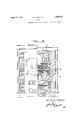
Fig; '5 isa verticallsectiona'l'View similarv to Fig. l, of a modified form of boiler wherein on y'line taken between thiesheets' of the 'near n 4 isja side' 'elevation ofthe partsshown n .horizontal baille'plates inay be used and an prevent jthe'fgases coming into* Contact With fi thedruniiabove'the'level oftheWatfer. y -Figi' 6 shows diagranimatieally'dierentpy types of boilers, to'assist' `in the understandv now in general use? 'ing 'and-arrangementofparts of this finven- .tiongas compared ltoother forni's'of boilersfy preheating tub-es showingthe-expansion 'cors rugatlon's.'
ofthef steamdrinn and Circular Water' legs" assembled', with: the-Water tubes and preheati ing tubesioinitted.-
YFgil is a'detail perspective viewf'offon'e y ofthe partitionl plates adaptedto beinounted" 'y inv'tlie 'Water vleg .tov provide thesegregatd' portionif'thereofl With which "theL tubes are in Communioation:
Fig. .lO is a front view",fone Yhalf "sect-ion"` showing the improved iboilerinountingg Reference now being had'to the drawingsl y 85" preheating bymuinerals and to inaker' Clear' the relative'4 alllllgf'lleHS' oi parts' of' the improved boiler 'I as compared toboilers now on the market;spel4 cial reference is made to Fig: '6'in'whrchtlie` -vievv inarked A represents the forni oiboili-` er of the usualoonstruetiorrand referred to as-'a Water tube lboiler; "The-view; marked@ B? 'is a fragment ofav lire tube boiler .partly in'perspeo'tivle to show the shellam- 'lhe'view`vl markedl C "is the Jimproved type1 vof f-'vvate'r f' tube boiler shown in perspective, to indicate the absence of the shell, the location of the water tubes, the preheating tubes, and thel steam drum.
his invention is intended to provide a water tube boiler that will require little or no more head room than the ordinary lireV tube boilers, will have the efficiency of the-'water enced in the use of the present water tube boilers, which are partly illustrated in Fig. 6, view A wherein is shown in dotted lines in a diagrammatical manner, the variations that exist in the forms of boilers legs now in general use. variations inthe lower rectangular portion of the water legs as put out by different manufacturers for a given horsepower, the angle or taper of the upper portion of the water legs and the relative position of the steam drum. v y
`W'ith the present construction of the smaller sized .tube boilers, additional head room is required, which results in increased building costs which in many instances become prohibitive and necessitates the installation of the fire tube type of boiler, which again rev quires speciallarge openings be left in walls for their admission or their installation before the walls are completed, both of these objections are overcome by thev improved round leg water tube boiler which can be assembled on the job and boilers up to 200 horse power can be taken through the ordinary 3 feet 6 inches by 7 feet door opening, andthe headroom willnot exceed that of the ordi-- nary fire tube boiler. If a standard round leg water tube boiler such as herein submitted` is adopted, no provision for special shape of water leg will be necessary, since standard sizes of circular flanged heads suitable for forming the improved round water legs for different' horse powers, are a standard product of the steel mills. i V l i In illustrating this invention, the ordinary form of furnaces as seen. in Fig. 1 is used, wherein the front wall 1, the rear wall 2, the fire Wall 3, the combustion chamber 4, the lire chamber 5, the fire grates 6, the ash pit 7, and
cement foundation A8 are all of standard construction. f
The boiler which is of the water tube type consists of circular water'legs 9 and 10, said water legs being of a. corresponding construction and are interchangeable, facilitating assembling and laying out. The water legs are The dotted lines indicate the connected by a steam drum 11, arranged between the upper portions of the circular legs. Water tubes are arranged beneath the steam drum as shown at 12 and nests of preheating tubes flank the steamdrum on both sides as shownat13. i
In the arrangement of the parts shown, horizontal upper and lower baflle plates 14 and 15 respectively are provided. A flue leading to the stack as indicated at 16 is provided i for the passage of the gases from the combustion chamber beneath the lower baille plate 15 rearwardly -and then upwardly around the end of the same, forwardly ,between the baffle plates 14 and 15, around the forward end of baille plate 14 and back on itself in a rearwardly direction tothe flue 16, it being noted in the arrangement of baille plates shown th atv the gases turn over three times which may be increased by a re-arrangement of baille plates in eitherfcase insuring a perfect mixture of the gases, preventing stratification thereof and producing more complete combustion.
Numerous forms of boiler suspension are used in boiler setting and simply as a means of illustration, the improved boiler as shown is supported on pairs of I-beams 17-17, larranged across the frontand rear walls of the furnace, from which depend links 18-18 connected at their lower ends to vloops 19-19, secured to the water legs of theboiler.
The circular water legs 9 and 10 at the ends of the boiler, are identical in construction and a description of only one will be given. The Water leg consists of a tube sheet 21 (see Figs. 2 and 3) and a hand hole sheet 22. The tube sheet is preferably provided with flanges 23 and 24, and also with openings 25 and 26 in which the ends of water tubes 12 and preheating tubes 13 respectively, are secured in the usual manner. An end of the steam drum V11 snugly fits flange 23 of the tube sheet and is secured thereto by rivets or other preferred means. Y
Drain or blow-off pipe opening 27 is provided at the lower portion of the water leg, from which pipe 28 (see Fig. 1) vmay extend to any desired point, it being noted that said drain or blow-ofi' pipe is fully protected throughout its entire length, from the direct heat of the furnace. Hand hole sheet 22 is preferably shaped steel as .is the tube sheet and is kprovided with a'llange 29, adapted to.
being closed by plate and yoke, and key plugs respectively, in the usual manner.
Arranged in the water leg oneach side of its connection with the steam drum, are segregated chambers 32 formed by plates 33 adapta counter How of the-liquidl-in Vthe tubes and the gases. i
Communicating with thesegre'gated, chambers `theloWerle'n'd ofth'eboiler'fare inlet pipesfl asishown' invFi'gsfl andQ and connecting said inlet pipes" is a yoleff 36 adaptedtore'i boilerA are foutlet pipes 383m' E'conneetionffvvith' theE segregated ch'ambersfat fthe upper-f end of the boiler; said pipes `38` being sc'oim'ected; by' a' T 39f7 which through -'pipe connection .40.;- valve LHand-pipe 42 eonveys preheated' -Waterffrom the segregated eh'a'rnbers vlat @the upper end Iof the boiler downtov the waterleg beneathfltheman hole opening 30 as shownlat 43;"1Figv3; Said 'opening 43; notis'howir) fat-fthe'opposite or :lower vend of; "Ghefboil'l" i's' Provided t0 f the-2 lhieifarefinL this -inventirr 1 circulated .a removable plug (notshown);
Stay; bolts' fle-of the?usualilconstruction;
either hollow, drilled ends ory solid 'a s shown are' provided5 having rsuflici'ent fcross'r'sectio'nf and spacing ifor the' required f workin g pres# Sure; i i
'InfFigl 5 is showny a slightly modiiiedlform of Athe: application ofI my* improved-#boiler wlfrerein =the ourrentsffof the products of cour-f lastfga'spass the` remaining heat therein or 'a E' 'largef portion-foi it'i'staken i'up Sby the contents 'i The; f operation of the--structure 4showI'i-jin Fig. 1 provides for the fiow of the produets noted' thatlthe preheating--tubesare'arranged uelandlthatiduri-ng thev4 passageof the gases orithe `products" 'off combustion vthrough said .ofI th'ef -prehe'ating tubes.;
The farrangement ofthe vparts -f here ofconrbustion about the Water tubes in a direc- -tion opposite to the liow of water therein Vand --fuitiher provides for fthe? ,absorptionro the pipe-37; At'the opposite orfupper end'sfoffthel provides forfthecirclulat-i'oniof theproduets* 2 theyy have beenrreduced to such a degree 'asfto goes throng-mbe: preheating tubes:
combinedi'boiler 'andlpreheaterin-a single unity lower water leg, passes lfrom saidfsegregat` -f ed chambers through-ithe prelre'ating 'tubes to -whereinff'waterfsupplied through pipe i 37 and v T736 en-ters :the-segregated chambersoji'the 1 y the-segregated Chambers :in f the upper lwater bust-ion' follow 'diiier'entficoufrsesfrom' thatfwhichit enters'the'watertubesandis eonvert"- shown in Fig. l l. The baffle" plates are" lar ranged in ll-`a vertical 'position-1insteadfofffm horizontal Y positionIsf-as shown 'intheifpre-f peraturefof theravaterin'itspassage throng-li ferred forma# Y It will bel noted :that f1 baiil'eplate's l45"+.-%l6' cause the products f of 'combustion Y'tolA folle an upand down direction through the Water tubes' and lthat there 'areA-plates- 46a arranged on opposite sides of the steam drum to prevent any contact between the products Ofcombustion7 and the steam drum above the water line.
For the same reason as described in the preceding paragraph vertical plates 47 as seen in Figs. l and 10 are provided on either side Toi" the steam drum to prevent contact between the cooled gases of combustion and the steam drum above the Water line. It Will be understood that by the time the products of combustion have circulated about the water tubes and the preheating tubes and rise to the upper and rearward passages toI the flue if the temperature therein has been reduced below that of steam, contact with the steam drum above the water line would be objec- `tionable -f cientlyhigh' degree, `as to` avoid the neeessritA7 lf-:for providingn for expansion inotherv than theffprelreating tubes as shown? the preheating tubes is brought to such a su'if# ItL is furtheri noted' 'ithatfjthere is j anfunl'f restricted fconrmunieatron 7 between the steam d1'-u1nfand the waiterflegs, this as `:1n numerous otherf-'particularsflis different from Ithe @usualpraeti'cefwherein thecOmmuniCatiOn ibetween t thefSteimJdr-UIHYaI-rd tlrewater leg is'fthrough slits'arranged around a yportion ofH the 'Giri cumfer'eneef'foffthe steam 'drumiil The .coni saturation-@here shown provides for free `circul lation andkmorerapld generation.
The* construction shown 1 provides for fb' and includes in a single unit within safi'duni:
95er; This E4'inventionffthereforeprovidesfiorL af heater and utilization of heat' ordinarilyl Wasted.
the generator,rwhich may be providedwith corrugations to compensate for the movement of-the VWater legs due to irregular expansion of the tubes. It will also be understood that the inflow of cold water into the preheating tubes varies to a considerable degree, While the lower steam generating tubes remain at practically a .uniform temperature, said corrugations provide forthe movement of the Water legs due to the irregular expansion of the tubes. y 1
Having thus described my invention, what I claim as new and desire to secureby Letters Patent is: y
1. -A watery tube boiler having circular water legs, a steam drum connecting the Water legs, segregated chambers arranged in the water legs at opposite sides of the steam drum connections, water tubes connecting the Water legs, preheating tubes connecting the segregated chambers and means for supplyingwater tothe segregated chambers of. one water leg and fromthe segregated lchambers ofthe other leg to the lastnamed water leg of the boiler. v
2. A Water tube boilerihazving circularA water legs, a steam drum, water tubes and preheating tubes arranged between the water legs within the .diameter of the circular water legs and means for supplying water to the preheating tubes and means for conveying water from the preheating tubes to the water tubes.
3. A Water tube boiler having circular water legs, segregated chambers arranged in the water legs, a steam drumandwater tubes connecting the waterlegs withinjthe diameter of said water legs,rpreheating tubes connecting the segregated chambers and means for Vsupplying water to the segregated chambers of one Water leg and from the segregated chambers of the other leg to thelast named water leg of the boiler. n v.
4. A water tube boiler having circular waterlegs, pairs of segregated chambers arranged in saidlegs, a steam drum and Water tubes in communication with the water legs and preheating tubesconnecting said segregated chambers of the water legs all within the-diameter of said legs, means for supplying water to the segregated chambers of one water leg and means forconveying water from the Vsegregated chambers to the water legs. A.
5. A water `tube vboiler having `circular lleg ofthe boiler.
Water vvlegs, a steam drum connecting the upper portion of the waterlegs, segregated portions in the water legs on opposite sides of Ythe drum connections, vwatertubes convnecting the lower portion of the water legs,
corrugated preheating tubes arranged on either side ofthe steam drum connecting the segregated portions of the Waterlegs, means for supplying the preheatin tubes with water and means for .conveylng preheated water from the preheating tubes to a water leU.
D6. A` water tube boiler having circular water legs, a steam drum connecting. the upper portions of the water legs, segregated chambers arranged in the water legs'on opposite sides of the steam drum connections,
preheating tubes arranged on each side of the drum' and connecting. the; segregated chambers on corresponding sides of the steam drum, water tubes arranged below said steam drum and .preheating tubes, connecting the water legs, means for supplying water to the segregated chambers of one leg and means for conveying waterfrom the segregated chambersof the other'leg, to the last named water n 7.' The combination Withafurnacehavinga fire chamber, a flue andmeans adaptedto form circuitous gas passes between the fire chamber and the flue, of a tilted water tube boiler having circular water legs, segregated chambers within the water legs, a steam drum and water. .tubes connecting the water legs, corrugated preheating tubes connecting the segregated chambers in the water legs and arranged in the lastV gas pass, said tubes and drum being allv arranged within the diameter of the Water legs, means for supplying water to said segregated chambers at the lower end of theLboiler, means for conveying water from said segregatedlchambers at the upper end Vof the boiler to the water leg and a baille arrangedv to prevent the gases coming into vcontact with the steam drum above the water `lineQ MICHAEL E. MILLER.
Priority Applications (1)
| Application Number | Priority Date | Filing Date | Title |
|---|---|---|---|
| US208573A US1853372A (en) | 1927-07-26 | 1927-07-26 | Boiler |
Applications Claiming Priority (1)
| Application Number | Priority Date | Filing Date | Title |
|---|---|---|---|
| US208573A US1853372A (en) | 1927-07-26 | 1927-07-26 | Boiler |
Publications (1)
| Publication Number | Publication Date |
|---|---|
| US1853372A true US1853372A (en) | 1932-04-12 |
Family
ID=22775096
Family Applications (1)
| Application Number | Title | Priority Date | Filing Date |
|---|---|---|---|
| US208573A Expired - Lifetime US1853372A (en) | 1927-07-26 | 1927-07-26 | Boiler |
Country Status (1)
| Country | Link |
|---|---|
| US (1) | US1853372A (en) |
-
1927
- 1927-07-26 US US208573A patent/US1853372A/en not_active Expired - Lifetime
Similar Documents
| Publication | Publication Date | Title |
|---|---|---|
| US1853372A (en) | Boiler | |
| US3107656A (en) | Boilers having a combustion chamber encircled with water tubes | |
| US1764981A (en) | Locomotive boiler and fire box | |
| US1971068A (en) | Boiler | |
| US797107A (en) | Steam-boiler. | |
| US790792A (en) | Steam-generator. | |
| US330126A (en) | Steam-boiler | |
| US2248891A (en) | Boiler and other heat exchangers | |
| US1707418A (en) | Furnace for water-tube steam boilers | |
| US227475A (en) | pefess | |
| US1762136A (en) | Water-tube steam boiler | |
| US762893A (en) | Steam-generator. | |
| US1684976A (en) | Steam generator and the like | |
| US1740337A (en) | Steam generator | |
| US530017A (en) | Sectional steam-generator | |
| US363802A (en) | Disteict of | |
| US2455621A (en) | Fire and water tube boiler | |
| US800906A (en) | Steam-boiler. | |
| US861330A (en) | Water-tube steam-generator. | |
| US253082A (en) | Steam-boiler | |
| US816530A (en) | Steam-boiler. | |
| US544245A (en) | Sectional steam or hot-water boiler | |
| US424646A (en) | Steam-boiler | |
| MacNaughton | Elementary steam power engineering | |
| US1663806A (en) | Boiler |