US1853250A - Grab - Google Patents
Grab Download PDFInfo
- Publication number
- US1853250A US1853250A US546002A US54600231A US1853250A US 1853250 A US1853250 A US 1853250A US 546002 A US546002 A US 546002A US 54600231 A US54600231 A US 54600231A US 1853250 A US1853250 A US 1853250A
- Authority
- US
- United States
- Prior art keywords
- grab
- head
- cross
- secured
- rods
- Prior art date
- Legal status (The legal status is an assumption and is not a legal conclusion. Google has not performed a legal analysis and makes no representation as to the accuracy of the status listed.)
- Expired - Lifetime
Links
- 238000010276 construction Methods 0.000 description 4
- MJBPUQUGJNAPAZ-AWEZNQCLSA-N butin Chemical compound C1([C@@H]2CC(=O)C3=CC=C(C=C3O2)O)=CC=C(O)C(O)=C1 MJBPUQUGJNAPAZ-AWEZNQCLSA-N 0.000 description 2
- 241001233887 Ania Species 0.000 description 1
- 241000507564 Aplanes Species 0.000 description 1
- MJBPUQUGJNAPAZ-UHFFFAOYSA-N Butine Natural products O1C2=CC(O)=CC=C2C(=O)CC1C1=CC=C(O)C(O)=C1 MJBPUQUGJNAPAZ-UHFFFAOYSA-N 0.000 description 1
- 230000001419 dependent effect Effects 0.000 description 1
- 230000003455 independent Effects 0.000 description 1
- QVRVXSZKCXFBTE-UHFFFAOYSA-N n-[4-(6,7-dimethoxy-3,4-dihydro-1h-isoquinolin-2-yl)butyl]-2-(2-fluoroethoxy)-5-methylbenzamide Chemical compound C1C=2C=C(OC)C(OC)=CC=2CCN1CCCCNC(=O)C1=CC(C)=CC=C1OCCF QVRVXSZKCXFBTE-UHFFFAOYSA-N 0.000 description 1
- 230000000630 rising effect Effects 0.000 description 1
Images


Classifications
-
- B—PERFORMING OPERATIONS; TRANSPORTING
- B66—HOISTING; LIFTING; HAULING
- B66C—CRANES; LOAD-ENGAGING ELEMENTS OR DEVICES FOR CRANES, CAPSTANS, WINCHES, OR TACKLES
- B66C3/00—Load-engaging elements or devices attached to lifting or lowering gear of cranes or adapted for connection therewith and intended primarily for transmitting lifting forces to loose materials; Grabs
- B66C3/06—Grabs actuated by a single rope or chain
- B66C3/08—Grabs actuated by a single rope or chain and having tipping rings
Definitions
- ThlSiiIlVQIlt-iOIl relates to grabs of the type known as single rope rlng discharge grabs andlit has for its object a construction which will enable greater digging powe'rstobe emiployed without the necessity for increaslng the strength: and weight of'the parts designed for maintaining the grabinits openposition.
- This invention resides more particularly in the provision-oi means for maintaining the bucket sections in the open position when the grab is being released from the tipping ring andfor taking the stresses tending to close the same, comprising one or more verticallydisposed'rods ca-rri'ed'by" a part p'iv otally mounted on the head of the grab and 5 arranged to coact with means carriedby the cross-beam;
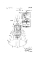
- Figure-1 is a frontelevation of the grab supported by the hauling rope with the bucket sections in the closed position
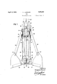
- Figure 2 is aside'eleVatiQn thereof;
- Figure 3 is asimilar-v-iew to Figure 2 with thebucketsections in the open position; the i grab being supported by the tipping ring;
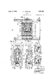
- Figure ' is a plan of the grab Figure 5 is: aplan of the cross-beam;
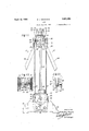
- Figure 6 is a side elevation, partly in section, of partof the head o-fthe grab;
- Figure T is a-front elevation, partlyin section, thereof;
- Figure 9 is'a'fronteie'vationof the lower part'of Figure 7 showingTthe partsin a (lit fer-ent. position; a
- Figure 10 is la: side elevation of t the upper parto f a grab, with parts -inithe-closed p0- sition,showing a-modified form of' the means forretaining the bucket sections-inithe open pos1t1on-;
- F igure' 12 is: a transverse section on: line: l212of Figure 1-1 Figure l3' illustrates detail of construetion;
- Figure- 14 is a transverse section on line" 14.''14 of F igure 11
- Figure 15 is sectionalside" elevation o'n'i line'15'.15 of Figure l i;
- Figure 18 is a transversesection ofparfi of the head of the rab: on line 18 18iof Fi giirel r' of a modified form" of the means" for retaining the bucket sections in the open position;
- the centre partotthfe headot-thegfabbtweenthe plates-27 Figure 4) j is; built upaof a seriesof plates to formazboxlike-rstructurei open top and bottom, divided internally to form two compartments disposed in parallel relation to the pivot pins 26 and in the lower part of which are pivoted the purchase sheaves 32 and 34, third compartment being formed in the centre in which is secured the tliimble 30, on the upper part ofuvhich the hook shaped elements 36 coacting' with the tipping ring 28 are mounted.
- a sleeve 37 (see Figures 6 to 9) provided with two oppositely disposed vertically arranged slots 38 adapted to receive the horizontally disposed lower ends 39 of the elements 36; the lower end of the sleeve 37 is of rectangular form and fits between the plates 40 forming the compartment in which the thimble 30 is secured, the lower end being provided, one on either side, with extensions 41, the inner faces of which are cut at an angle and are arranged to coact with a narrow rectangular plate 42 supported by a stirrup shaped plate 43 secured to the plates 40 so as to have a limited rotative movement relatively thereto, a ball bearing 44 being preferably disposed between the stirrup plate 43 and the plate 42 to give greater freedom of movement.
- the plate 42 is provided on its upper face with a tubular member 45 adapted to enter and rotate in the lower part of the sleeve 37 and on its lower face, one at either end, with two bosses 46 in which are secured the upper ends of two downwardly extendin rods 47.
- said sheave being disposed with its axis of rotation in parallel relation with the longitudinal axis of the cross-beam and at right angles to the axes of the sheaves 32 and 34 mounted in the head of the grab, so that the groove on both sides of said sheave is immediately beneath the grooves on one side of each of the sheaves 32 and 34.
- a second sheave 31 is located in the adjacent compartment 50, said sheave being mounted in a housing 51, pivoted at 52 in a bracket 53 secured to the plate 54.
- the other end of the housing 51 is arranged to slide freely in a vertically disposed guide 55 secured to the plate 56.
- the housing 51 is disposed at an angle to the longitudinal axis of the beam and is so arranged that the groove in the sheave adjacent the guide 55 is at the plane of its axis, in the vertical axis of the grab, that is, directly below the axis of the thimble 30 and the other side of the groove is in a direct line with the sheave 32.
- the housing 51 is furnished on its exterior, adjacent the guide 55, with two bosses 57 in which are secured the lower ends of two upwardly extending rods 58, slightly shorter than the rods 47, the arrangement being such that when the grab is open and when being supported by the ring, the rods 47 are coaxially disposed with relation to the rods 58 ( Figure 3).
- the free ends of the rods are adapted to butt against each other and in order to maintain the respective rods in alignment the free ends of the rods 58 are recessed and the free ends of the rods 47 are formed so as to seat in said recesses.
- the number of moving parts of the grab is reduced, thereby reducing the weight of the grab; in this construction the sleeve 37 is replaced by a sliding block 61 which is furnished with the oppositely disposed slots 38 and acts in a similar manner to said sleeve.
- the lower end of the block 61 is cut away as shown at 62 ( Figure 13) and coacts with an arm 63 pivoted at 64 in lugs 65 provided on the plate 65.
- the arm 63 is provided with a socket 66 in which is secured the upper end of a downwardly directed rod 67, the lower end of which is arranged to coact with a socket 68; carried thecnossbeam. 23-,
- the sleeve 37 is replaced by a sliding block 61 which is furnished with the oppositely disposed slots 38 and acts in a similar manner to said sleeve.
- the lower end of the block 61 is cut away as shown at 62 ( Figure 13) and coacts with an arm 63 pivoted at 64 in lug
- a grab of thesingle rope type having; a. cross-beam with pulleys. mounted, therein; 1 and in the headof the grabandzaitipping-ring; the combination. of means comprising; hOOk-s shaped elements carriedby the head, of: they grab adapted to coact with said'tippingring, means having a limited rotative movement mounted on thehead of the grab, means-man ried by and depending from said notatiwe, meansand means carried by the cross-beam adapted to coact with the saididepending I means for maintaining the grabintheopeni position.
- member means comprlslng a,spring fonmaimg the combination of means' comprising.
- a grab of the single rope type having a cross-beam with pulleys mounted therein and in the head of the grab and a tipping ring
- the combination of means comprising a pair of hook-shaped elements carried by the head of the grab adapted to coact with the tipping ring, lugs secured to the head of the grab, a horizontally disposed arm pivoted in said lugs, a downwardly extending rod secured to said arm, a block having a vertical slidin movement in said head, means on the crossearn comprising a horizontally and transversely disposed plate, a socket carried by said plate, means comprising a spring for maintaining the downwardly extending rod in axial alignment with said socket, means on the lower end of the sliding block adapted when said part falls into its lowest position to bear against the pivoted arm so as to rotate same in its pivot and thereb move the downwardly extending rod out o coincidence with the socket on the cross-beam.
- a grab of the single rope type having a cross-beam with pulleys mounted therein and in the head of the grab and a tipping ring
- the combination of means comprising a pair of hook-shaped elements carried by the head of the grab adapted to coact with the'tipping ring, lugs secured to the head of the grab, a vertically disposed trunnion pivotally mounted in said lugs, a downwardly extending rod of H-section secured to said trunnion, ablock having a vertical sliding movement in said head, means on the crossbeam' comprising a horizontally and transversely disposed plate, an aperture formed in said ,plate corresponding in shape with the shape of the downwardly extending rod, means comprising a spring for maintaining the downwardly extending rod out of coincidence with said aperture, means on the lower end of the sliding block adapted when said part falls into its lowermost position to bear against the upper end of the downwardly extending arm so as to impart a limited rotative' movement thereto and bring said
- a grab of the single rope discharge type comprising a cross-beam, a pair of bucket sections pivoted thereon, a box-like structure built up of a plurality of plates constituting the head of the grab, a plurality of sheaves mounted in the crossbeam and head of the grab, spreader arms connecting the cross-beam with the head of the grab, a thimble secured in the head of the grab, hook- V shaped elements slidably and pivotally mounted in said thimble, a tipping ring with which said hook-shaped elements coact, a slidable element arranged in said thimble coacting with the lower ends of said hook-shaped elements, a rotatable element mounted on the head of the grab, a spring for controlling said rotatable element, means provided on the lower end of the slidable element adapted to turn said rotatable element against the action of the spring, means depending from and carried by said rotatable element and means carried by the cross-beam adapted to coact with the depending means
- a grab of the single rope discharge type comprising a cross-beam, a pair of bucket sections pivoted thereon, a box-like structurebuilt up of a plurality of plates constituting the head of the grab, a plurality of sheaves mounted in the cross-beam and head of the grab, spreader arms connecting the cross-beam with the head of the grab, a thimble secured in the head of the grab, hookshaped elements slidably and pivotall mounted in said thimble, a tipping ring with which said hook-shaped elements coact, a
- slidable element arranged in said thimble coacting with the lower ends of said hookshaped elements, a rotatable element mounted on the underside of the head of the grab, cam surfaces provided on the lower end of the slidable element coacting with said rotatable element, means comprising a pair of downwardly extending rods carried by said rotatable element, means comprising a sheave housing pivotaly mounted on the cross-beam and means comprising a pair of upwardly extending rods carrled by said housing adapted to coact with the downwardly extending rods to maintain the grab in the open position.
- a grab of the single rope discharge type comprising a cross-beam, a pair of bucket sections pivoted thereon, a. box-like structure built up of a plurality of plates constituting the head of the grab, a plurality of sheaves mounted in the cross-beam and head of the grab, spreader arms connecting the cross-beam with the head of the grab, a thimble secured in the head of the grab, hookshaped elements slidably and pivotally mounted in said thimble, a.
- a sleeve slidably arranged in said thimble coacting with the lower ends of said hookshaped elements, extensions on the lower end of said sleeve, a rotatable element comprising a plate coacting with said extensions, a tubular member on the upper face of said plate adapted to enter and rotate in the lower end of the sleeve, a stirrup shaped element secured to the lower part of the head of the grab for supporting said rotatable element, a ball bearing located between said element and stirrup, cam surfaces provided on the extensions on the slidable sleeve coactingwith said rotatable element, means comprising a pair of downwardly extending rods carried by said rotatable element, means comprising an angularly disposed sheave housing pivotally mounted in the cross-beam, bosses provided on said housing adjacent its free end, and means secured in said bosses comprising a pair of upwardly extending rods
- a grab of the single rope discharge type comprising a cross-beam, a pair of bucket sections pivoted thereon, a box-like structure built up of a plurality of plates constituting the head of the grab, a plurality of sheaves mounted in the cross-beam and head of the grab, spreader arms connecting the crossbeam with the head of the grab, a thimble secured in the head of the grab, hook-shaped elements slidably and pivotally mounted in said thimble, a tipping ring with which said hook-shaped elements coact, an element comprising a block slidably arranged in said thimble coacting with the lower ends of said hook-shaped elements, a rotatable element mounted on the head of the grab comprising a spring controlled pivoted arms, means comprising a downwardly extending rod carried by said arm, a camsurface provided on the lower end of the slidable block adapted to coact with said spring controlled arm, means comprising a transverse plate secured to the cross-beam, a socket
- a grab of the single rope discharge type comprising a cross-beam, a pair of bucket sections pivoted thereon, a box-like structure built up of a plurality-of plates constituting the head of the grab, a plurality of sheaves mounted in the cross-beam and head of the grab, spreader arms connecting the cross-beam with the .head of the grab, a thimble secured in the head of the grab, hookshaped elements slidably and pivotally mounted in said thimble, a tipping ring with which said hook shaped elements coact, an element comprising a block slidably arranged in said thimble coacting with the lower ends of said hook-shaped elements,a rotatable element mounted on the head of the grab, comprising a spring controlleddownwardly extending, rod of H-section in cross-section, a cam surface provided on the upper end of said rod, a cam surface provided on the lower end of the slidable block coacting with the cam surface on the rotatable element, and means
Landscapes
- Engineering & Computer Science (AREA)
- Mechanical Engineering (AREA)
- Load-Engaging Elements For Cranes (AREA)
Description
April 1932 D. J. BARNARD 1,853,250
GRAB Filed June 22. 1931 7 Sheets-Sheet l l/VI/ENTOR ATTORNEY April 1932 D. J. BARNARD 1,853,250
GRAB
Filed June 22', 1931" 7'Sheets-Sheet 2 Fig. 2.
D. J. BARNARD GRAB April 12, 1932.
Filed June 22, 1931 Fig. 3.
7 Sheets-Sheet 3 IN V15 N 7' 0R April 1932- D. J. BARNARD 1,853,250
GRAB
Filed June 22, 1931 7 Sheets-Sheet 4 25 I Fig. 4.
April 12, 1932. D. J. BARNARD GRAB 'Filed June 22. 1931 7 Sheets-Sheet 5 April 12, 1932. J, BARNARD 1,853,250
GRAB
Filed June 22, 1931 7 Sheets-Sheet 6 //VV[/V TOR.
ATTORNEY By r I April 1932. D. J BARNARD 1,853,250
GRAB
Filed June 22. 1931 7 Sheets-Sheet. 7
Fig.18.
Patented Apr. 12, 1932 DUDLEY JAMES BARNARD, or BARKINQENGLAND' GRAB Application filed June'22; 1981; Serial No. 546,002, anrf i'n-Great Britain Tune 25, 1930."v
ThlSiiIlVQIlt-iOIl relates to grabs of the type known as single rope rlng discharge grabs andlit has for its object a construction which will enable greater digging powe'rstobe emiployed without the necessity for increaslng the strength: and weight of'the parts designed for maintaining the grabinits openposition. The grab forming the sul qect of this 1n- Ventionis of known forinin so'far as it is icomposedof two bucket sections pivoted on independent pivot pins on a transverse crossbeam with spreader armsat eachouter corner of thebucket sections, theupper ends of said armsbeingpivoted on independent pivotpins secured in block plates which constitute the head otthe grab.
This invention resides more particularly in the provision-oi means for maintaining the bucket sections in the open position when the grab is being released from the tipping ring andfor taking the stresses tending to close the same, comprising one or more verticallydisposed'rods ca-rri'ed'by" a part p'iv otally mounted on the head of the grab and 5 arranged to coact with means carriedby the cross-beam;
In=the ecompanyingdrawings which ii lust-rate this invention Figure-1 isa frontelevation of the grab supported by the hauling rope with the bucket sections in the closed position;
Figure 2 is aside'eleVatiQn thereof; Figure 3 is asimilar-v-iew to Figure 2 with thebucketsections in the open position; the i grab being supported by the tipping ring;
Figure 'is a plan of the grab Figure 5 is: aplan of the cross-beam; Figure 6 is a side elevation, partly in section, of partof the head o-fthe grab; Figure T is a-front elevation, partlyin section, thereof;
Figure 8-is acsection on line 88offFigure 7';
Figure 9 is'a'fronteie'vationof the lower part'ofFigure 7 showingTthe partsin a (lit fer-ent. position; a
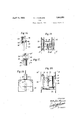
Figure 10 is la: side elevation of t the upper parto f a grab, with parts -inithe-closed p0- sition,showing a-modified form of' the means forretaining the bucket sections-inithe open pos1t1on-; I
Figure llisa similar view'with the parts in-the open position; i r
F igure' 12 is: a transverse section on: line: l212of Figure 1-1 Figure l3' illustrates detail of construetion;
Figure- 14 is a transverse section on line" 14.''14 of F igure 11 Figure 15 is sectionalside" elevation o'n'i line'15'.15 of Figure l i;
Figure 161s a of construction Figure 17 is a: side elevation" of parttott' the mechanismshown'in Figure'l8iasiviewedffrom the line=l7'1 7 Figure 18 is a transversesection ofparfi of the head of the rab: on line 18 18iof Fi giirel r' of a modified form" of the means" for retaining the bucket sections in the open position;
Figure lwis a sectional? elevation onrline 19 -1 9: of Figure 2O, -an'd Figure '20:is apla n of 'Feigure 191 1 perspective View of :11 detail Referring to Figu'resl to 9 0i the d-raiwr ings whichillustrate one embodiment of' the invention, 1 the main body of? the grab". is: of known form in thatit is composed: ofi two bucket sections='20,:21, pi'voted'on independ ent' piVot* pins 22 on a 'tran'sverse cross beamv- 23" with spreader armsQpiVoteda-t 25130;
each outer corner of the bucket sections, the upper ends ofsaid-arms being piirotedlonlin dependent pivot pins 26, secured? inblock plates' 27 which constitutethe' head ofthe -l grab; 28*is" the tipping ring-"suspended from: the j ib "of-theerane and 129 the haulingrope f 01-" chain; hereinafter referred ton-as the ihitil-l ing'rope; arrangedto pass throngh the ring QS'and the :thiinblei 3O secured-tothea hea'chof the grab, around the-sheave231; upwardlyand' over the 'sheave 32, downwardly an-daroundthe sheave 33; upwardly; and over theshea-ve 341M161 finally downwardly-to the; part 35 by me ans-of which the free-endis secured td thef cross-beam23'. V
The centre partotthfe headot-thegfabbtweenthe plates-27 Figure 4) j is; built upaof a seriesof plates to formazboxlike-rstructurei open top and bottom, divided internally to form two compartments disposed in parallel relation to the pivot pins 26 and in the lower part of which are pivoted the purchase sheaves 32 and 34, third compartment being formed in the centre in which is secured the tliimble 30, on the upper part ofuvhich the hook shaped elements 36 coacting' with the tipping ring 28 are mounted. Slidably arranged within the thimble 30 is a sleeve 37 (see Figures 6 to 9) provided with two oppositely disposed vertically arranged slots 38 adapted to receive the horizontally disposed lower ends 39 of the elements 36; the lower end of the sleeve 37 is of rectangular form and fits between the plates 40 forming the compartment in which the thimble 30 is secured, the lower end being provided, one on either side, with extensions 41, the inner faces of which are cut at an angle and are arranged to coact with a narrow rectangular plate 42 supported by a stirrup shaped plate 43 secured to the plates 40 so as to have a limited rotative movement relatively thereto, a ball bearing 44 being preferably disposed between the stirrup plate 43 and the plate 42 to give greater freedom of movement. The plate 42 is provided on its upper face with a tubular member 45 adapted to enter and rotate in the lower part of the sleeve 37 and on its lower face, one at either end, with two bosses 46 in which are secured the upper ends of two downwardly extendin rods 47.
The cross-beam 23 igure 5) to which the extreme ends of the bucket sections 20, 21, are pivoted, is built up of av series of plates to form a box-like structure open top and bottom divided internally to form a plurality of compartments in one of which 48, is pivotally mounted at 49, the purchase sheave 33. said sheave being disposed with its axis of rotation in parallel relation with the longitudinal axis of the cross-beam and at right angles to the axes of the sheaves 32 and 34 mounted in the head of the grab, so that the groove on both sides of said sheave is immediately beneath the grooves on one side of each of the sheaves 32 and 34. A second sheave 31 is located in the adjacent compartment 50, said sheave being mounted in a housing 51, pivoted at 52 in a bracket 53 secured to the plate 54. The other end of the housing 51 is arranged to slide freely in a vertically disposed guide 55 secured to the plate 56. As shown, the housing 51 is disposed at an angle to the longitudinal axis of the beam and is so arranged that the groove in the sheave adjacent the guide 55 is at the plane of its axis, in the vertical axis of the grab, that is, directly below the axis of the thimble 30 and the other side of the groove is in a direct line with the sheave 32.
The housing 51 is furnished on its exterior, adjacent the guide 55, with two bosses 57 in which are secured the lower ends of two upwardly extending rods 58, slightly shorter than the rods 47, the arrangement being such that when the grab is open and when being supported by the ring, the rods 47 are coaxially disposed with relation to the rods 58 (Figure 3). The free ends of the rods are adapted to butt against each other and in order to maintain the respective rods in alignment the free ends of the rods 58 are recessed and the free ends of the rods 47 are formed so as to seat in said recesses.
In operation, assuming the grab to be open and supported on the ring as shown in Figure 3, the hauling rope 29 being slack, there is a small gap between the ends of the rods 47 and 58, when the hauling rope 29 is drawn in, the housing 51 is drawn upwardly and in rising brings the rods 58 into engagement with the rods 47 and these rods take, in a vertical direction, the stresses tending to close the bucket sections, thereby mainta ning same in the open position. Further drawing in of the hauling rope raises the entire grab, and the elements 36 are free to fall outwardly by reason of the fact that the weight of the sleeve 37 is removed from the ends 39, said sleeve being maintained in its upper position by the engagement of the angularly faced extensions 41 bearing against the plate 42 (Figure 9). \Vhen the grab is lowered onto the ground or material to be raised, and the hauling rope paid out slightly, the housing 51 is free to dro and causes the disengagement of the rods 41 and 58; immediately this takes place the sleeve 37, which is of considerable weight, which may be increased by the provision of a suitable spring, falls into its lowermost position and the extensions 41 bearing agamst the plate 42, turn said plate on its bearings against the action of suitably disposed springs 59 (Figure 8). The axes of the rods 47 and 58 now being out of coincidence, if the hauling rope 29 is now hauled in, the grab may be closed; the lower ends of the rods 47 pass through the cross-beam and the upper ends of the rods 58 pass into recesses 60 provided in the lower part of the thimble 30 (Figure 6). t
In the embodiment of the invention illustrated in Figures 10 to 15, the number of moving parts of the grab is reduced, thereby reducing the weight of the grab; in this construction the sleeve 37 is replaced by a sliding block 61 which is furnished with the oppositely disposed slots 38 and acts in a similar manner to said sleeve. The lower end of the block 61 is cut away as shown at 62 (Figure 13) and coacts with an arm 63 pivoted at 64 in lugs 65 provided on the plate 65. The arm 63 is provided with a socket 66 in which is secured the upper end of a downwardly directed rod 67, the lower end of which is arranged to coact with a socket 68; carried thecnossbeam. 23-, The
main, parts ot the cross-beam are S UbSiiLIl. tlally; the same as; above described: with referencetoEigu-res L to9J-,.butin this embodiment the housing 6.9 is immovably secured to. the. Gross-beam; and; the socket 68 isv ca1:-- I'Idqbfl transversely disposed memberTO,
said: member being; located approximately in. the vertical; centreot thegrab; The socket which therod- 6? is adapted to pass during theiclosingmovement of the bucket sections. 'Ehe; socket 68; is further provided with an aperture 7 2 through which the hauling rope 29-isadapteda to. pass .tothe sheave 31.,
In, operation, assuming; the grab to be open; and supported by the ring: 28- as shown in Figure 11, the hauling ropebeing slack,
thelower'end of their-0d 6 7; isout 0t coincidance; with the aperture '71 (Figure 1 1). Then. the, hauling rope is drawn in the crossrbea-m isdrawn up slightly until: the
end of therod 67. bears against the bottom of; the socket 685 thereby preventing the closingot the-bucket sections. Further drawing. 1n; ot the hauling: rope raises the'ent-n'e grab may be closed, the rod. 67 passing through the. aperture. 71 andguidetube 7 L asshown by'broken lines'in Figure 15.
In; order toJstilL further simplify. the construction. of'thev grab, reduce-the number of parts andithereby the weight,.and to lrender the operation of certain-. parts. more certain, particularly when the grab isdisposed at an angleon aiheap-of material to be raised, the ulDBfiIlS for maintaining the bucket sections int-he open position may bemodiliedas shown in. Figures 16 to 20, according to which the depending rod'75 isof H or I' section in crosssectionand is furnished at its upper end with trunnion 76 rotatably mounted in the lugs -onthe-plate 65, and at its-lower end with atrunnion 7 7 rotatably mounted in a transversely arranged plate 78 securedto the cross.- beam23. Theupper endof the rod? 5 is furnishedwith a formof camsurface 79 preferably formed in one'with the lower part of the trunnion 76' adapted to coact with the angularly. fonmedzfjace 80 on the sliding part 6 1, in a similar manner to'that previously described...
'llhe plate TS-isprovided with: an aperture 810i thesame shape but slightly larger than the-dzb the positionpf said aperture being Q5" such that whenitherod isturnedinoneposi- ."is; fiurnish-ed with an aperture 7.1 throughv now thehauling rope ishauledinrthe grab tion it coincides with said apertune and is: freeto slide therethrough; j In operation, v assuming-the bucket sections. to be in the open position and the grab sup ig ported on, the ring, the hauling rope being; slack, the rod 7 5 is held by the spring 82; so. that the lower end. of said rod isout or. co incidence with the, aperture 81in; the plate; 78 (Figure 2O)v and rests on said plate when; the grab is released from the ring and, (1:87 posited; on; the ground in themanner previously described the rod 75 isturned ()IlyItSg pivot against th'eaction or" the springby the; falling of the sliding-member: 61-soas to'blfillgu said rod into coincidence with the; aperture 81. If now thehauling ropeishauledf in the; grab may be closed; the rod 75 passing; through the aperture8l, I a
lVl1'at.I-clai1n-is:, x 1. In a grab of thesingle rope type having; a. cross-beam with pulleys. mounted, therein; 1 and in the headof the grabandzaitipping-ring; the combination. of means comprising; hOOk-s shaped elements carriedby the head, of: they grab adapted to coact with said'tippingring, means having a limited rotative movement mounted on thehead of the grab, means-man ried by and depending from said notatiwe, meansand means carried by the cross-beam adapted to coact with the saididepending I means for maintaining the grabintheopeni position. i
2. In a grab of the single rope type haying a.
cross-beam with pulleys mounted therein and. in the head of the grab and a tipping ring, the combination of means comprising hookshaped elements carried by the headof' the.- grabadapted to coact. with. said tipping ring means mounted on the head of the grab comrz prising a plate having a limited; rotatiuez movement, two downwardly extending rods.
secured to the undersideof saidplate,;1neans mounted on the cross-beam comprisingtwo upwardly extending rods, means comprising. a pair of springs for maintaining the. down: wardly and upwardly extending rods in,ania;lalignment, and means-sliidably mountedin the; head of the grab for effecting a partial rotar' tive movement of the plate carrying; the: downwardly extending rodstomouesameouil of coaxialv alignment with theupwardly eX.-.- tenrging rods when itis desired to} closethe; gra
3. In a grab of the single rope typezhavinae" a cross-beam with pulleys mounted-:thereim and in the head of. the ring, hook-shaped elements carried by the head Of{ the grab adapted tocoact with saidtipping ring, means comprising an armvpiyoted, on the head of the grab, a downwardly eXtend-- ing rod secured to one endofsaid arm meansq grab and. a; tipping;
mounted on the cr0ss-beam comprisingai.
socket carried by a transversely disposed; member means comprlslng a,spring fonmaimg the combination of means' comprising.
taining the downwardly extending rod in axial alignment with said socket, a block slidably arranged in the head of the grab coacting with the hook-shaped elements, a cam surface formed on the lower end of said block adapted to coact with the pivoted arm for efiecting a limited rotative movement of the arm to move the downwardly extending rod out of axial alignment with the socket when it is desired to close the grab.
4. In a grab of the single rope type having a cross-beam with pulleys mounted therein and in the head of the grab and a tipping ring, the combination of means comprising a pair of hook-shaped elements carried by the head of the grab adapted to coact with the tipping ring, lugs secured to the head of the grab, a horizontally disposed arm pivoted in said lugs, a downwardly extending rod secured to said arm, a block having a vertical slidin movement in said head, means on the crossearn comprising a horizontally and transversely disposed plate, a socket carried by said plate, means comprising a spring for maintaining the downwardly extending rod in axial alignment with said socket, means on the lower end of the sliding block adapted when said part falls into its lowest position to bear against the pivoted arm so as to rotate same in its pivot and thereb move the downwardly extending rod out o coincidence with the socket on the cross-beam.
5. In a grab of the single rope type having a cross-beam with pulleys mounted therein and in the head of the grab and a tipping ring, the combination of means comprising a pair of hook-shaped elements carried by the head of the grab adapted to coact with the'tipping ring, lugs secured to the head of the grab, a vertically disposed trunnion pivotally mounted in said lugs, a downwardly extending rod of H-section secured to said trunnion, ablock having a vertical sliding movement in said head, means on the crossbeam' comprising a horizontally and transversely disposed plate, an aperture formed in said ,plate corresponding in shape with the shape of the downwardly extending rod, means comprising a spring for maintaining the downwardly extending rod out of coincidence with said aperture, means on the lower end of the sliding block adapted when said part falls into its lowermost position to bear against the upper end of the downwardly extending arm so as to impart a limited rotative' movement thereto and bring said rod into coincidence with the aperture in the plate carried by the cross-beam.
6. A grab of the single rope discharge type, comprising a cross-beam, a pair of bucket sections pivoted thereon, a box-like structure built up of a plurality of plates constituting the head of the grab, a plurality of sheaves mounted in the crossbeam and head of the grab, spreader arms connecting the cross-beam with the head of the grab, a thimble secured in the head of the grab, hook- V shaped elements slidably and pivotally mounted in said thimble, a tipping ring with which said hook-shaped elements coact, a slidable element arranged in said thimble coacting with the lower ends of said hook-shaped elements, a rotatable element mounted on the head of the grab, a spring for controlling said rotatable element, means provided on the lower end of the slidable element adapted to turn said rotatable element against the action of the spring, means depending from and carried by said rotatable element and means carried by the cross-beam adapted to coact with the depending means carried by the rotatable element for maintaining the grab in the open position.
7 A grab of the single rope discharge type, comprising a cross-beam, a pair of bucket sections pivoted thereon, a box-like structurebuilt up of a plurality of plates constituting the head of the grab, a plurality of sheaves mounted in the cross-beam and head of the grab, spreader arms connecting the cross-beam with the head of the grab, a thimble secured in the head of the grab, hookshaped elements slidably and pivotall mounted in said thimble, a tipping ring with which said hook-shaped elements coact, a
slidable element arranged in said thimble coacting with the lower ends of said hookshaped elements, a rotatable element mounted on the underside of the head of the grab, cam surfaces provided on the lower end of the slidable element coacting with said rotatable element, means comprising a pair of downwardly extending rods carried by said rotatable element, means comprising a sheave housing pivotaly mounted on the cross-beam and means comprising a pair of upwardly extending rods carrled by said housing adapted to coact with the downwardly extending rods to maintain the grab in the open position.
8. A grab of the single rope discharge type, comprising a cross-beam, a pair of bucket sections pivoted thereon, a. box-like structure built up of a plurality of plates constituting the head of the grab, a plurality of sheaves mounted in the cross-beam and head of the grab, spreader arms connecting the cross-beam with the head of the grab, a thimble secured in the head of the grab, hookshaped elements slidably and pivotally mounted in said thimble, a. tipping ring with which said hook-shaped elements coact, a sleeve slidably arranged in said thimble coacting with the lower ends of said hookshaped elements, extensions on the lower end of said sleeve, a rotatable element comprising a plate coacting with said extensions, a tubular member on the upper face of said plate adapted to enter and rotate in the lower end of the sleeve, a stirrup shaped element secured to the lower part of the head of the grab for supporting said rotatable element, a ball bearing located between said element and stirrup, cam surfaces provided on the extensions on the slidable sleeve coactingwith said rotatable element, means comprising a pair of downwardly extending rods carried by said rotatable element, means comprising an angularly disposed sheave housing pivotally mounted in the cross-beam, bosses provided on said housing adjacent its free end, and means secured in said bosses comprising a pair of upwardly extending rods adapted, when the sliding sleeve is in its uppermost positidn, to coact with the downwardly extending rods carried by the rotatable element for maintaining the grab in the open position.
9. A grab of the single rope discharge type, comprising a cross-beam, a pair of bucket sections pivoted thereon, a box-like structure built up of a plurality of plates constituting the head of the grab, a plurality of sheaves mounted in the cross-beam and head of the grab, spreader arms connecting the crossbeam with the head of the grab, a thimble secured in the head of the grab, hook-shaped elements slidably and pivotally mounted in said thimble, a tipping ring with which said hook-shaped elements coact, an element comprising a block slidably arranged in said thimble coacting with the lower ends of said hook-shaped elements, a rotatable element mounted on the head of the grab comprising a spring controlled pivoted arms, means comprising a downwardly extending rod carried by said arm, a camsurface provided on the lower end of the slidable block adapted to coact with said spring controlled arm, means comprising a transverse plate secured to the cross-beam, a socket carried by said transverse plate with which the lower end of the downwardly extending rod is adapted to coact to maintain the grab in the open position.
10. A grab of the single rope discharge type, comprising a cross-beam, a pair of bucket sections pivoted thereon, a box-like structure built up of a plurality-of plates constituting the head of the grab, a plurality of sheaves mounted in the cross-beam and head of the grab, spreader arms connecting the cross-beam with the .head of the grab, a thimble secured in the head of the grab, hookshaped elements slidably and pivotally mounted in said thimble, a tipping ring with which said hook shaped elements coact, an element comprising a block slidably arranged in said thimble coacting with the lower ends of said hook-shaped elements,a rotatable element mounted on the head of the grab, comprising a spring controlleddownwardly extending, rod of H-section in cross-section, a cam surface provided on the upper end of said rod, a cam surface provided on the lower end of the slidable block coacting with the cam surface on the rotatable element, and means comprising a transverse plate secured to the cross-beam with which the lower end of the rotatable element is adapted to coact to maintain the grab in the open position.
DUDLEY JAMES BARNARD.
Applications Claiming Priority (1)
| Application Number | Priority Date | Filing Date | Title |
|---|---|---|---|
| GB1853250X | 1930-06-25 |
Publications (1)
| Publication Number | Publication Date |
|---|---|
| US1853250A true US1853250A (en) | 1932-04-12 |
Family
ID=10892009
Family Applications (1)
| Application Number | Title | Priority Date | Filing Date |
|---|---|---|---|
| US546002A Expired - Lifetime US1853250A (en) | 1930-06-25 | 1931-06-22 | Grab |
Country Status (1)
| Country | Link |
|---|---|
| US (1) | US1853250A (en) |
-
1931
- 1931-06-22 US US546002A patent/US1853250A/en not_active Expired - Lifetime
Similar Documents
| Publication | Publication Date | Title |
|---|---|---|
| US1853250A (en) | Grab | |
| US989744A (en) | Jack. | |
| US1573203A (en) | Grab-bucket-crane toy | |
| US967116A (en) | Extension fire-ladder. | |
| US1908028A (en) | Jib crane | |
| US1544969A (en) | Lifting and dumping or ring-discharge grab | |
| US1621701A (en) | Tongs | |
| US1218921A (en) | Grab. | |
| US497952A (en) | Tower-wagon | |
| US1358621A (en) | Tilting furnace or like structure | |
| US1519194A (en) | Window raising and lowering means | |
| US870812A (en) | Grab-bucket and operating mechanism. | |
| GB183569A (en) | Improvements in bottom discharge buckets and the like | |
| US937496A (en) | Clam-shell bucket. | |
| US1733236A (en) | Lifting tongs | |
| US1168279A (en) | Grab-bucket. | |
| US516864A (en) | Conveyer-carriage | |
| US60442A (en) | Otis tufts | |
| US1973668A (en) | Hydraulic hoist-lever construction | |
| US774978A (en) | Dumping-wagon. | |
| US1534049A (en) | Lifeboat davit | |
| US1007130A (en) | Clam-shell bucket. | |
| US1482116A (en) | Grab | |
| US84749A (en) | Improved coal-chute | |
| US936093A (en) | Kettle-hanger. |