US185308A - Improvement in car-couplings - Google Patents
Improvement in car-couplings Download PDFInfo
- Publication number
- US185308A US185308A US185308DA US185308A US 185308 A US185308 A US 185308A US 185308D A US185308D A US 185308DA US 185308 A US185308 A US 185308A
- Authority
- US
- United States
- Prior art keywords
- head
- car
- bar
- couplings
- coupling
- Prior art date
- Legal status (The legal status is an assumption and is not a legal conclusion. Google has not performed a legal analysis and makes no representation as to the accuracy of the status listed.)
- Expired - Lifetime
Links
- 238000010168 coupling process Methods 0.000 title description 7
- 238000005859 coupling reaction Methods 0.000 title description 7
- 238000010276 construction Methods 0.000 description 4
- 230000008878 coupling Effects 0.000 description 3
- YSGQGNQWBLYHPE-CFUSNLFHSA-N (7r,8r,9s,10r,13s,14s,17s)-17-hydroxy-7,13-dimethyl-2,6,7,8,9,10,11,12,14,15,16,17-dodecahydro-1h-cyclopenta[a]phenanthren-3-one Chemical compound C1C[C@]2(C)[C@@H](O)CC[C@H]2[C@@H]2[C@H](C)CC3=CC(=O)CC[C@@H]3[C@H]21 YSGQGNQWBLYHPE-CFUSNLFHSA-N 0.000 description 1
Images

Classifications
-
- B—PERFORMING OPERATIONS; TRANSPORTING
- B60—VEHICLES IN GENERAL
- B60D—VEHICLE CONNECTIONS
- B60D1/00—Traction couplings; Hitches; Draw-gear; Towing devices
Definitions
- A represents a draw-bar of usual shape and construction, except at its outer end or head A', which lat- 'ter is provided with a Vertical slot, a, that has parallel sides, and extends from the said outer end longitudinally inward to a point considerably in rear of the usual opening for the reception of the link.
- the slot or recess a is fitted a block, B, which loosely fills the same, and restores the outlines of the head A', and is provided with a longitudinalopening, b, which'has ⁇ the usual bell-mouth or Vflaring outer end, and is intended for the reception of 'a coupling-link, G, of ordinary construction.
- the head-block B is connected to or with the draw-head by means of a bolt, E, which passes transversely through said draw-head, and through the rear end of said head-block, -and forms a pivoted bearing for ⁇ and upon which the latter may move in a Vertical plane, for the purpose hereinafter described.
- an arin, B' which extends vertically upward to a point somewhat farther from the pivoted center of said block than is the outer end of the latter, and at its upper end is made wedge-shaped, and upon each side, at said end, is provided with an A-shaped projection, b, as shown in Figs. 1 and 2.
- a crank-shaped bar, E' is journaled within the upper portion of each of the draw-heads A', at the front line of the arm B', with its fl-shaped portion bearing against the the pivoted bearings e of each bar E' isprof..H
- crank-bar E' not only operates to lock the head-blocks in position to enable the link O to be used, but said bar also furnishes a means whereby the coupling-bars may be released from engagement whenever it is desired to diseonnect the cars.
- the head-block B provided with the recess b, pin-openings b' and b', and couplingbars B' b, in combination with the draw-head A', having the recess a., substantially as and for the purpose shown.
- crank-bar E journaled within the drawhead A', and the stop G, secured upon said draw-head, and engaging with said par, substantially as and for the purpose set orth.
Landscapes
- Engineering & Computer Science (AREA)
- Transportation (AREA)
- Mechanical Engineering (AREA)
- Soil Working Implements (AREA)
Description
i z shees-shm 1.
W m MW... 4.1,/ N ll z, W .I/
z sheets-sheet z.
J. G. FISHER.
cAR-coUPLING. No. 185,308. Patenzed Dec.1z,1878.
fly-4- JosnPH GgFIsHER, OF TOLEDO, Assienon To HiMsnLF, wM. R. nonrnaor SAME-.PLAGE, AND EDWARD W. KELLY, OF PAINESV'ILLE, OHIO.
IMPRovl-:MENT IVN.CAR-couPuNes.4`
Specification forming partof Letters Patent No. 185,308, dated December 12, 1876 ;vapplication filed May 2 5, 1876. i
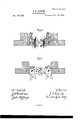
To all tchem it may concern Be it known that I, J osEPH G. FISHER, of Toledo, in the county of Lucas, and .in the State of Ohio, have invented certain new and useful Improvements in Car-Couplings; and do hereby deolare that the following is a full, clear, and exact description thereof, reference being had to the accompanying drawings, making a part of this specification, in which- Figure l is a `perspective view of my im` proved device arranged for use with links and coupling-pins of ordinary construction. Fig. 2 is a like view of the same arranged for the engagement of the hooked-end coupling-bars; and Figs. 3 and 4 are, respectively, Vertical longitudinal sections of Figs. 1 and 2 upon central lines.
Letters of like name and kind refer to like parts iu eaoh'of the figures.
The design of my invention'is to enable ordinary links and pins to be used, when necessary, upon or in connection with car-couplings in which hooked-end coupling-bars are employed; and to this end- It consists, principally, in a car-coupling in which the outer end of the draw-bar is provided with a head that contains two forms of eoupling, and is so pivoted orjournaled as to permit either form to be presented in position for use, substantially as and for the purposes hereinafter specified.
It consists, further, in the peculiar construction of the pivoted or journaled head-block, substantially as and for the purposes hereinafter shown.
It consists, further, in the means employed for changing the position of and securing in place the pivoted head-block, substantially as and for the purposes hereinafter set forth.
In the annexed drawings, A represents a draw-bar of usual shape and construction, except at its outer end or head A', which lat- 'ter is provided with a Vertical slot, a, that has parallel sides, and extends from the said outer end longitudinally inward to a point considerably in rear of the usual opening for the reception of the link.
WVithin the slot or recess a is fitted a block, B, which loosely fills the same, and restores the outlines of the head A', and is provided with a longitudinalopening, b, which'has `the usual bell-mouth or Vflaring outer end, and is intended for the reception of 'a coupling-link, G, of ordinary construction. A round opening, b', passing vertically through said block B nearits outerend, receives a common coupling-pin, D, whichv pin engages with and looks said link in place. i
The head-block B is connected to or with the draw-head by means of a bolt, E, which passes transversely through said draw-head, and through the rear end of said head-block, -and forms a pivoted bearing for` and upon which the latter may move in a Vertical plane, for the purpose hereinafter described.
Upon the upper side, at the rear end, of the head-block B is provided an arin, B', which extends vertically upward to a point somewhat farther from the pivoted center of said block than is the outer end of the latter, and at its upper end is made wedge-shaped, and upon each side, at said end, is provided with an A-shaped projection, b, as shown in Figs. 1 and 2.
When the coupling-pins D and D' and the link O are removed, and the head'blocks B and B turned downward to the position shown in Figs. 2 and 4, the lower face of each of said heads will impinge upon the rear Vertical wall of the slot a, and prevent the arms or bars B' and B' from passing below a horizontal line, while the weight of said heads will incline said arms to return to position whenever raised above such lines.
When the pivoted heads are thus arranged,
if the couplings are moved toward each other, the outer end of one of the bars B' will be raised by the outer end of the other bar, and will pass rearward over the latter until the lower ends of its A-shaped projections b" and b drop in rear of and engage with the corresponding upper projections b" and b" of said lower bar, in which positions said bars B' and B' operate to connect the cars together.
In order that the pivoted heads may be raised to and seoured in the position shown in Figs. l and 3, a crank-shaped bar, E', is journaled within the upper portion of each of the draw-heads A', at the front line of the arm B', with its fl-shaped portion bearing against the the pivoted bearings e of each bar E' isprof..H
vided a handle, F, by means of which said bar ,may beturned. toorfrom a horizontal po-.
sition, and when occupying a Vertical position said bar may be .locked in place by moving the same laterally, for which purpose a little end motion is allowed, until one of its Vertical portions passes behind and `eng'ag'es with a stop, G, that is secured upon the contiguous portion of the draw-head A'.' v
'It will be scen that the crank-bar E' not only operates to lock the head-blocks in position to enable the link O to be used, but said bar also furnishes a means whereby the coupling-bars may be released from engagement whenever it is desired to diseonnect the cars.
When'the ordinary links and pins are employed said parts will require the usnal manipulatio'n; but When the coupling-bars are used the couplin g is effected by sim ply baoki n g' the cars together, and the uncoupling,` by means of the orank-bars at one side of said cars.
Having' thns fully set forth the nature and lmerits of my invention, what I vclaim as new .1..,A.oarconpling in which the-router` end of the draw-bar is provided with a head-that contains two forms of couplings, and is so vpivoted or journaled as to permit either form of coupling to be presented. in position for use, suhstantiall-y as andffor the purpose specified.
- 2. The head-block B, provided with the recess b, pin-openings b' and b', and couplingbars B' b, in combination with the draw-head A', having the recess a., substantially as and for the purpose shown.
3. In combination with the pivoted headblock B B' the crank-bar E, journaled within the drawhead A', and the stop G, secured upon said draw-head, and engaging with said par, substantially as and for the purpose set orth.
'In testimony'that I claim the foregoingl have hereunto set my hand this 20th day of May, 1876.'I
JOSEPH G. FISHER.
Witnesses':
JOHN F. KUMLER, ALoNzo A. Lo'r'r.
Publications (1)
| Publication Number | Publication Date |
|---|---|
| US185308A true US185308A (en) | 1876-12-12 |
Family
ID=2254713
Family Applications (1)
| Application Number | Title | Priority Date | Filing Date |
|---|---|---|---|
| US185308D Expired - Lifetime US185308A (en) | Improvement in car-couplings |
Country Status (1)
| Country | Link |
|---|---|
| US (1) | US185308A (en) |
-
0
- US US185308D patent/US185308A/en not_active Expired - Lifetime
Similar Documents
| Publication | Publication Date | Title |
|---|---|---|
| US185308A (en) | Improvement in car-couplings | |
| US335611A (en) | Jambs franklin moorman | |
| US279658A (en) | Car-coupling | |
| US461065A (en) | Car-coupling | |
| US155883A (en) | Improvement in car-couplings | |
| US297829A (en) | Car-coupling | |
| US386854A (en) | skinner | |
| US317889A (en) | titus | |
| US376482A (en) | Car-coupling | |
| US189689A (en) | Improvement in car-couplings | |
| US124430A (en) | Improvement in railway-car couplings | |
| US491976A (en) | Car-coupling | |
| US180016A (en) | Improvement in car-couplings | |
| US222926A (en) | Improvement in car-couplings | |
| US422796A (en) | Car-coupling | |
| US418732A (en) | Car-qoupling | |
| US558620A (en) | Car-coupling | |
| US295860A (en) | And william melvob | |
| US459502A (en) | Car-coupling | |
| US192544A (en) | Improvement in car-couplings | |
| US459904A (en) | Car-coupling | |
| US219206A (en) | Improvement in car-couplings | |
| US489659A (en) | Car-coupling | |
| US263221A (en) | Car-coupling | |
| US148227A (en) | Improvement in car-couplings |