US1853073A - Bottle stopper - Google Patents
Bottle stopper Download PDFInfo
- Publication number
- US1853073A US1853073A US552977A US55297731A US1853073A US 1853073 A US1853073 A US 1853073A US 552977 A US552977 A US 552977A US 55297731 A US55297731 A US 55297731A US 1853073 A US1853073 A US 1853073A
- Authority
- US
- United States
- Prior art keywords
- bottle
- neck
- inner face
- stopper
- figures
- Prior art date
- Legal status (The legal status is an assumption and is not a legal conclusion. Google has not performed a legal analysis and makes no representation as to the accuracy of the status listed.)
- Expired - Lifetime
Links
- 241001411320 Eriogonum inflatum Species 0.000 title description 7
- 239000000463 material Substances 0.000 description 5
- 230000002093 peripheral effect Effects 0.000 description 3
- 230000006978 adaptation Effects 0.000 description 1
- 239000004576 sand Substances 0.000 description 1
- 239000000126 substance Substances 0.000 description 1
Images
Classifications
-
- B—PERFORMING OPERATIONS; TRANSPORTING
- B65—CONVEYING; PACKING; STORING; HANDLING THIN OR FILAMENTARY MATERIAL
- B65D—CONTAINERS FOR STORAGE OR TRANSPORT OF ARTICLES OR MATERIALS, e.g. BAGS, BARRELS, BOTTLES, BOXES, CANS, CARTONS, CRATES, DRUMS, JARS, TANKS, HOPPERS, FORWARDING CONTAINERS; ACCESSORIES, CLOSURES, OR FITTINGS THEREFOR; PACKAGING ELEMENTS; PACKAGES
- B65D49/00—Arrangements or devices for preventing refilling of containers
- B65D49/02—One-way valves
- B65D49/04—Weighted valves
Definitions
- This invention relates to bottle stoppers.
- the essential objects of the invention are to ensure a lateral discharge at one or more points of the contents of a bottle; t0 retard sand divide the contents of the bottle when travelling towards the point or points of lateral discharge; to prevent the surreptitious filling of a bottle after the contentsthereof has been emptied; to prevent the entrance of 'io'foreign substances into the bottle; to prevent the adulteration of the contents of the bottle; to prevent tampering with the valve element of the stopper; to provide a removable-closure for the lateral discharge opening 15 or openings; and toattain these ends in a strong, durable, thoroughly efficient and comparatively inexpensive structure.
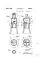
- Figure 1 is a vertical sectional View of a bot- "tle stopper, in accordance with this invention showing the adaptation thereof with respect to a bottle neck. 7
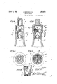
- Figure 2 is alike view of a modified form.
- Figure 3 is a section on'line 3-3 Figure 1;
- Figure 4 is a section on line 4+4 Figure 2.
- Figure 5 is a section on line 55 Figure 1.
- Figure 6 is a view similar to Figure 1 of still another modified form. 1
- Figure 7 is a view'similar to Figure 1 of still another modified form.
- Figure 8 is a section on line 88 Figure 6.
- Figure 9 is a sectionon line 99 Figure 8.
- Figure 10 is a fragmentary view in vertical section of still another modified form.
- the stopper when positioned relative to the'neck l of a bottle is securely anchored thereto, by a suitable cementitious material arranged against the inner face of and on the edge of the neck. 7
- the stopper ' includes an annular member formed of an inner part 2, an intermediate part 3 and an outer part 4.
- the part 2i is of less diameter than part 2 to provide an annular shoulder 5.
- the part 4 is of less diameter than part 2.
- the part 3 is formed with an inwardly STOPPER 1931. Serial No. 552,977.
- annular flange 6' which merges into the inner end of part 4 and the latter opens into part 3.
- the outer end of part 4 is closed as at 7 and in proximity to the closed outer end of such part it is provided with a series of equally spaced radially disposed openings 8 providing outlets for lateral discharge of the contents of the bottle.
- the lower portion of the inner face of part 3 andithe upper portion of the inner face of part 2 are curvedv as at 9, 10 respectively.
- Formed integral with the inner face of the part 3 and the curved portions 9, 10 is a pair of intersecting, diametrically disposed, oppositely extending,
- the elements 11 and 12 intersect at the verticalmedians thereof'disposed at the axis of the bot-' tle neck.
- the lower edges 13 of the elements 11, 12 are of arcuate 'contoiir.
- the upper edges 14 of said elements are squared
- Mounted on the part4 is a removable closure cap 15 for the openings 8. i
- the shoulder 5 seats on the edge 16 of the neck 1 and is secured therewith by the cementitious material referred to.
- the diameter -of part 2 relative to the .inner diameter of neck 1 is such as to provide tight fit and in connection with the cem'entitious material referred to said part 2 is securely anchored to neck 1.
- FIG. 6 and 8 The form shown in Figures 6 and 8 is the same as that shown in F iguresl, 3 and 5, With this exception that there is fixedly secured to the inner face of part 2, at the inner portion of the latter an'annulus 16 having a beveled top 17 to provide a seat for a ball valve 18. The elements 11,12 limit the outward shift of valve 18. Otherwise than that as stated the form shown by Figures 6 and 8 is identically the same as that shown by Figures 1, 3 and 5 and is anchored to the bottle neck in the same manner. The form shown in Figures 6 and 8 is of that type to prevent, the refilling or 109 adulterating the contents of the bottle with which the stopper is used.
- the stopper includes an annular member formed of an inner part 19 and an outer part 20 opening into each other and with the outer part closed at its outer end, as at 21.
- the part 19 is of less diameter than the part 20 to provide an annular shoulder 22.
- the lower portion of the inner face of part 20 and upper portion of the inner face of part 1.9 are curved, as at 23, 2t respectively.
- Formed integral with the inner face of part 20 and the curved portions 23, 24 is a pair of intersecting, diametrically disposed, oppositely extending, upstanding, thin, substantially rectangular parti tion-likemembers or webs combined retarder and divider elements 25.
- the elements sect at the vertical media is tlnreo't disposed at the axis of the bottle neclr.
- the lower edges 27 of the elements 25, 26 are or" arc-0" c contour.
- the upper 28 of sai t ments are squared.
- the part 20 in proxi lty to its closed outer end 21 is formed with a plurality of equally spaced radially disposed openings 29 providing outlets for lateral discharge for the contents of the bottle. Mou ted on the part 20 is a removable closure cap ill) for the openings 29.
- the shoulder 22 seats on the edge 16 of the neck 1 and is secured therewith by the cementitious material referred to.
- the diameter of part 20 with respect to the inner diameter of the neck 1 is sues as to provide a tight fit and in connection with the cementitious material referred to said part 20 is securely anchored to neck 1.
- FIG. 7 and 9 The form shown in Figures 7 and 9 is the same as that shown in Figures and 4, with this exception that there is fixedly secured to the inner face. of part 19, at the inner portion of the latter an annulus 31 having a beveled upper top 32 to provide a seat for aball valve 34.
- the elements 25, 26 limit the outward shift of valve 34.
- the form shown by Figures 7 and 9 is identically the same as that shown by Figures 2 and 4 and is anchored to the bottle neck in the same manner.
- the form shown in Figures 7 and 9 is of that type to prevent the refilling or adulterating the contents of the bot tle with which the stopper is used.
- Fi The form shown by Fi" e 10 will be the same as that illustrated by A igure 6 or by Figure 7, with this exception that the annulus 35 for the ball valve 36, does not have its top beveled, but includes a pair of diametrically disposed, oppositely extendin intersecting webs 37 cut out in the top edges thereof to form a valve. seat 38.
- a bottle stopper including an annular member having a closed outer end, an open inner end for extension into the bottle neck and a peripheral shoulder for overlapping the mouth edge of the bottle neck, said member having radial openings in proximity to its closed end to provide lateral discharge points, and a pair of diametrically disposed, oppositely extendin upstanding, thin, substantially rectangu ar partition-like-members standing on their lower len hwise edges and providing combined retar er and divider elements integral at their ends with the inner face of said member intermediate the ends of the latter, intersecting each other at the axis of the bottle neck and forming in con- .ncction with said inner face quadrant shaped passages permanently open at their outer ends.
- a bottle stopper including an annular member having a closed outer end, an open inner end for extension into the bottle neck and a peripheral shoulder, said member having radial openings in proximity to its closed end to provide lateral discharge points, a pair oi": diametrically disposed, oppositely extending, upstanding, thin, substantially rectangular partition-like-members standing on their lower lengthwise edges and providing combined retarder and divider elements integral at their ends with the inner face of said member intermediate the ends of the latter, intersecting each other at the axis of the bottle neck and forming in connection with said inner face quadrant shaped passa permanently open at their outer ends, sa d edges being of arcuate contour, a ball valve within said member inwardly of said elements, and an annulus secured within said member at its inner end and providing a seat and a retainer for said valve.
- a bottle stopper including an annular member having a closed outer end, an open inner end for extension into the bottle neck and a peripheral shoulder for overlapping the mouth edge of the bottle neck, said member having radial openings in proximity to its closed end to provide lateral discharge points, a pair of diametrically disposed, o positely extending, upstanding, thin, su stantially rectangular partition-like-members standing on their lower len hwise edges and providing combined retar er and divider elements integral at their ends with the inner face of. said member intermediate the ends of the latter, intersecting each other at the axis of the bottle neck and forming in connectlon with said inner face quadrant shaped passages permanently open at their outer ends, and a removable closure for said discharge openings seating on said closed outer end.
Landscapes
- Engineering & Computer Science (AREA)
- Mechanical Engineering (AREA)
- Closures For Containers (AREA)
Description
April 12, 1932.
L. MOROSINI ET AL BOTTLE STOPPER Filed July 24, 1931 2 Sheets-Sheet l gwwmto'c Louis Morosz'n i Jose hjrico W April 1932. L. MOROSINI ET AL 1,353,073
BOTTLE STOPPER Filed July 24, 1931 2 Sheets-Sheet 2 Fij Lbuis Morosini Joseph Erica 20 parts as fall within Patented Apr. 12, 1932 v UNITED STATES PATENT OFFICE LOUIS MOROSINI AND JOSEPH ABICO, OF NEW YORK, N. Y., ASSIGNORS F ONE-THIRD TO JOHN F. MATTEO, OF NEW YORK, N. Y. e
BOTTLE Application filed July 24,
This invention relates to bottle stoppers. The essential objects of the invention are to ensure a lateral discharge at one or more points of the contents of a bottle; t0 retard sand divide the contents of the bottle when travelling towards the point or points of lateral discharge; to prevent the surreptitious filling of a bottle after the contentsthereof has been emptied; to prevent the entrance of 'io'foreign substances into the bottle; to prevent the adulteration of the contents of the bottle; to prevent tampering with the valve element of the stopper; to provide a removable-closure for the lateral discharge opening 15 or openings; and toattain these ends in a strong, durable, thoroughly efficient and comparatively inexpensive structure. v I
To the above ends essentially the invention "consists in such parts and combinations of the scope of the invention as claimed. e
a In the drawings: Figure 1 is a vertical sectional View of a bot- "tle stopper, in accordance with this invention showing the adaptation thereof with respect to a bottle neck. 7
Figure 2 is alike view of a modified form.
Figure 3 is a section on'line 3-3 Figure 1;
Figure 4 is a section on line 4+4 Figure 2.
Figure 5 is a section on line 55 Figure 1. Figure 6 is a view similar to Figure 1 of still another modified form. 1
Figure 7 is a view'similar to Figure 1 of still another modified form.
Figure 8 is a section on line 88 Figure 6.
Figure 9 is a sectionon line 99 Figure 8. Figure 10 is a fragmentary view in vertical section of still another modified form.
The stopper when positioned relative to the'neck l of a bottle is securely anchored thereto, by a suitable cementitious material arranged against the inner face of and on the edge of the neck. 7 Referring to Figures 1, 3 and 5 the stopper '"includes an annular member formed of an inner part 2, an intermediate part 3 and an outer part 4. The part 2iis of less diameter than part 2 to provide an annular shoulder 5. The part 4 is of less diameter than part 2. The part 3 is formed with an inwardly STOPPER 1931. Serial No. 552,977.
extending annular flange 6' which merges into the inner end of part 4 and the latter opens into part 3. The outer end of part 4 is closed as at 7 and in proximity to the closed outer end of such part it is provided with a series of equally spaced radially disposed openings 8 providing outlets for lateral discharge of the contents of the bottle. The lower portion of the inner face of part 3 andithe upper portion of the inner face of part 2 are curvedv as at 9, 10 respectively. Formed integral with the inner face of the part 3 and the curved portions 9, 10 is a pair of intersecting, diametrically disposed, oppositely extending,
upstanding, thin, substantially rectangular partition-like-members or Webs combined retarder and divider elements 11, 12 standing on their lower lengthwise edges 13 and which in connection with the inner face of part 3 provide quadrant shaped passages permanently open at their upper ends. The elements 11 and 12 intersect at the verticalmedians thereof'disposed at the axis of the bot-' tle neck. The lower edges 13 of the elements 11, 12 are of arcuate 'contoiir. The upper edges 14 of said elements are squared Mounted on the part4 is a removable closure cap 15 for the openings 8. i
The shoulder 5 seats on the edge 16 of the neck 1 and is secured therewith by the cementitious material referred to. The diameter -of part 2 relative to the .inner diameter of neck 1 is such as to provide tight fit and in connection with the cem'entitious material referred to said part 2 is securely anchored to neck 1.
The form shown in Figures 6 and 8 is the same as that shown in F iguresl, 3 and 5, With this exception that there is fixedly secured to the inner face of part 2, at the inner portion of the latter an'annulus 16 having a beveled top 17 to provide a seat for a ball valve 18. The elements 11,12 limit the outward shift of valve 18. Otherwise than that as stated the form shown by Figures 6 and 8 is identically the same as that shown by Figures 1, 3 and 5 and is anchored to the bottle neck in the same manner. The form shown in Figures 6 and 8 is of that type to prevent, the refilling or 109 adulterating the contents of the bottle with which the stopper is used.
Referring to Figures 2 and 4 the stopper includes an annular member formed of an inner part 19 and an outer part 20 opening into each other and with the outer part closed at its outer end, as at 21. The part 19 is of less diameter than the part 20 to provide an annular shoulder 22. The lower portion of the inner face of part 20 and upper portion of the inner face of part 1.9 are curved, as at 23, 2t respectively. Formed integral with the inner face of part 20 and the curved portions 23, 24 is a pair of intersecting, diametrically disposed, oppositely extending, upstanding, thin, substantially rectangular parti tion-likemembers or webs combined retarder and divider elements 25. 26 standing on their lower longitudinal edges 27 and which in connection with the inner face of part 20 provide quadrant shaped passages permene; i open at their upper ends. The elements sect at the vertical media is tlnreo't disposed at the axis of the bottle neclr. The lower edges 27 of the elements 25, 26 are or" arc-0" c contour. The upper 28 of sai t ments are squared. The part 20 in proxi lty to its closed outer end 21 is formed with a plurality of equally spaced radially disposed openings 29 providing outlets for lateral discharge for the contents of the bottle. Mou ted on the part 20 is a removable closure cap ill) for the openings 29.
The shoulder 22 seats on the edge 16 of the neck 1 and is secured therewith by the cementitious material referred to. The diameter of part 20 with respect to the inner diameter of the neck 1 is sues as to provide a tight fit and in connection with the cementitious material referred to said part 20 is securely anchored to neck 1.
The form shown in Figures 7 and 9 is the same as that shown in Figures and 4, with this exception that there is fixedly secured to the inner face. of part 19, at the inner portion of the latter an annulus 31 having a beveled upper top 32 to provide a seat for aball valve 34. The elements 25, 26 limit the outward shift of valve 34. Other 'ise than that stated, the form shown by Figures 7 and 9 is identically the same as that shown by Figures 2 and 4 and is anchored to the bottle neck in the same manner. The form shown in Figures 7 and 9 is of that type to prevent the refilling or adulterating the contents of the bot tle with which the stopper is used.
The form shown by Fi" e 10 will be the same as that illustrated by A igure 6 or by Figure 7, with this exception that the annulus 35 for the ball valve 36, does not have its top beveled, but includes a pair of diametrically disposed, oppositely extendin intersecting webs 37 cut out in the top edges thereof to form a valve. seat 38.
What we claim is 1. A bottle stopper including an annular member having a closed outer end, an open inner end for extension into the bottle neck and a peripheral shoulder for overlapping the mouth edge of the bottle neck, said member having radial openings in proximity to its closed end to provide lateral discharge points, and a pair of diametrically disposed, oppositely extendin upstanding, thin, substantially rectangu ar partition-like-members standing on their lower len hwise edges and providing combined retar er and divider elements integral at their ends with the inner face of said member intermediate the ends of the latter, intersecting each other at the axis of the bottle neck and forming in con- .ncction with said inner face quadrant shaped passages permanently open at their outer ends.
2. A bottle stopper including an annular member having a closed outer end, an open inner end for extension into the bottle neck and a peripheral shoulder, said member having radial openings in proximity to its closed end to provide lateral discharge points, a pair oi": diametrically disposed, oppositely extending, upstanding, thin, substantially rectangular partition-like-members standing on their lower lengthwise edges and providing combined retarder and divider elements integral at their ends with the inner face of said member intermediate the ends of the latter, intersecting each other at the axis of the bottle neck and forming in connection with said inner face quadrant shaped passa permanently open at their outer ends, sa d edges being of arcuate contour, a ball valve within said member inwardly of said elements, and an annulus secured within said member at its inner end and providing a seat and a retainer for said valve.
A bottle stopper including an annular member having a closed outer end, an open inner end for extension into the bottle neck and a peripheral shoulder for overlapping the mouth edge of the bottle neck, said member having radial openings in proximity to its closed end to provide lateral discharge points, a pair of diametrically disposed, o positely extending, upstanding, thin, su stantially rectangular partition-like-members standing on their lower len hwise edges and providing combined retar er and divider elements integral at their ends with the inner face of. said member intermediate the ends of the latter, intersecting each other at the axis of the bottle neck and forming in connectlon with said inner face quadrant shaped passages permanently open at their outer ends, and a removable closure for said discharge openings seating on said closed outer end.
In testimony whereof, we afiix our signatures hereto.
LOUIS MOROSINI. JOSEPH ARICO.
Priority Applications (1)
| Application Number | Priority Date | Filing Date | Title |
|---|---|---|---|
| US552977A US1853073A (en) | 1931-07-24 | 1931-07-24 | Bottle stopper |
Applications Claiming Priority (1)
| Application Number | Priority Date | Filing Date | Title |
|---|---|---|---|
| US552977A US1853073A (en) | 1931-07-24 | 1931-07-24 | Bottle stopper |
Publications (1)
| Publication Number | Publication Date |
|---|---|
| US1853073A true US1853073A (en) | 1932-04-12 |
Family
ID=24207609
Family Applications (1)
| Application Number | Title | Priority Date | Filing Date |
|---|---|---|---|
| US552977A Expired - Lifetime US1853073A (en) | 1931-07-24 | 1931-07-24 | Bottle stopper |
Country Status (1)
| Country | Link |
|---|---|
| US (1) | US1853073A (en) |
Cited By (2)
| Publication number | Priority date | Publication date | Assignee | Title |
|---|---|---|---|---|
| US3341046A (en) * | 1965-04-23 | 1967-09-12 | Astra De Bouchage Soc | Fluid-tight bottle cap |
| US3595421A (en) * | 1969-04-14 | 1971-07-27 | Jose Sanchis | Pour spout adapter |
-
1931
- 1931-07-24 US US552977A patent/US1853073A/en not_active Expired - Lifetime
Cited By (2)
| Publication number | Priority date | Publication date | Assignee | Title |
|---|---|---|---|---|
| US3341046A (en) * | 1965-04-23 | 1967-09-12 | Astra De Bouchage Soc | Fluid-tight bottle cap |
| US3595421A (en) * | 1969-04-14 | 1971-07-27 | Jose Sanchis | Pour spout adapter |
Similar Documents
| Publication | Publication Date | Title |
|---|---|---|
| US3073470A (en) | Insertable, self-locking and non-refillable closure for bottles | |
| US1853073A (en) | Bottle stopper | |
| US1974348A (en) | Paste tube cap | |
| US2091460A (en) | Bottle closure | |
| US2253738A (en) | Closure for tubes | |
| US2032305A (en) | Dispensing device for collapsible tubes | |
| US2362150A (en) | Self-closing bottle | |
| US2232129A (en) | Nonrefillable bottle | |
| US2053191A (en) | Nonrefillable bottle | |
| US2120491A (en) | Closure for containers | |
| US2199323A (en) | Nonrefillable bottle | |
| US2003873A (en) | Bottle closure | |
| US1321411A (en) | Non-refiuable bottle | |
| US1433803A (en) | Bottle stopper | |
| US2077026A (en) | Nonrefillable bottle | |
| DE361338C (en) | Bottle cap | |
| US1332231A (en) | Closure for non-refillable bottles | |
| US1038566A (en) | Non-refillable bottle. | |
| US1134242A (en) | Non-refillable bottle. | |
| US2226805A (en) | Safety seal for bottles and the like | |
| US1056797A (en) | Non-refillable bottle. | |
| US1023735A (en) | Bottle-stopper. | |
| US2073193A (en) | Flexible tube closure | |
| US1978304A (en) | Nonrefillable bottle | |
| US2137956A (en) | Nonrefillable attachment |